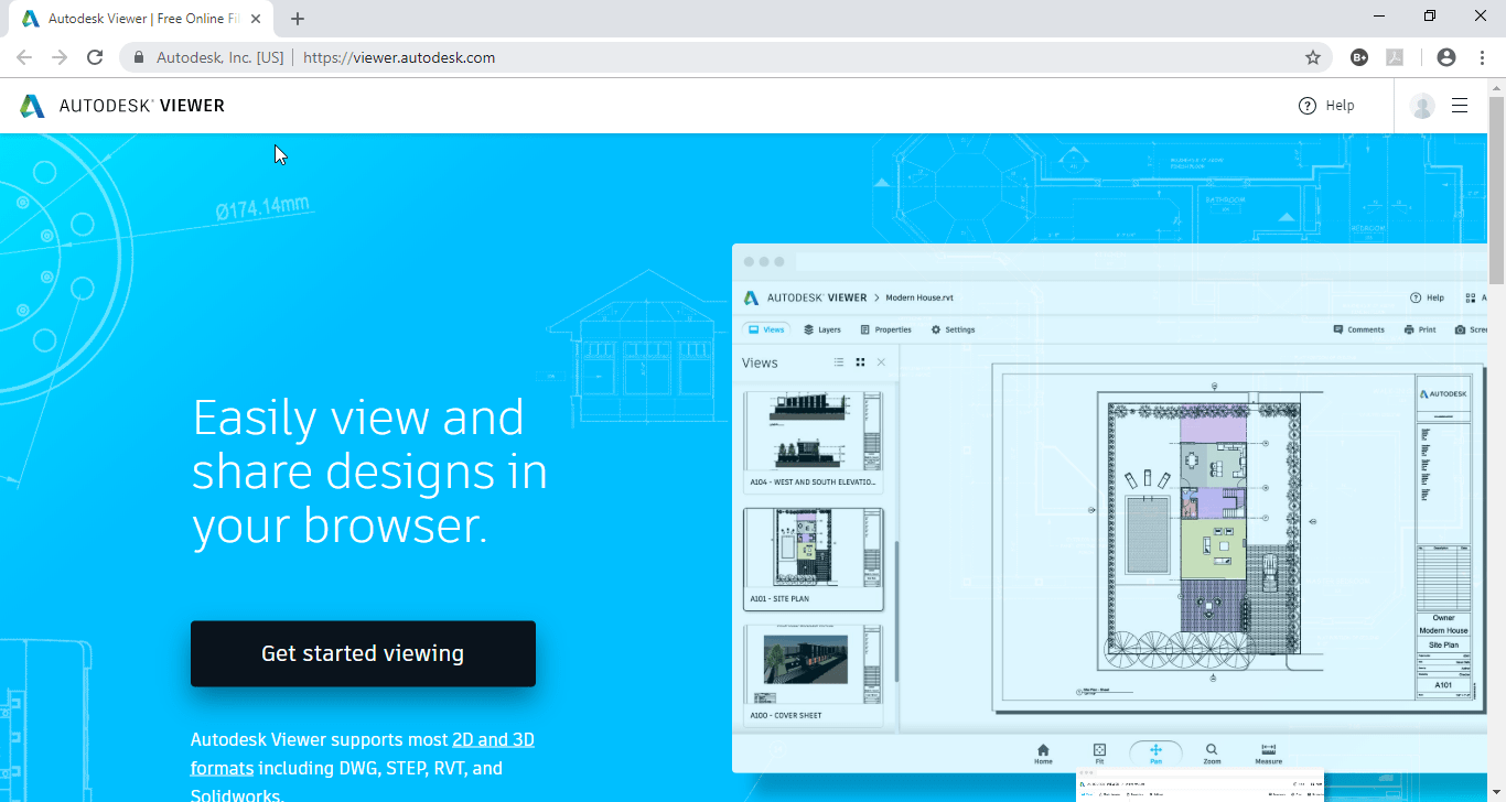
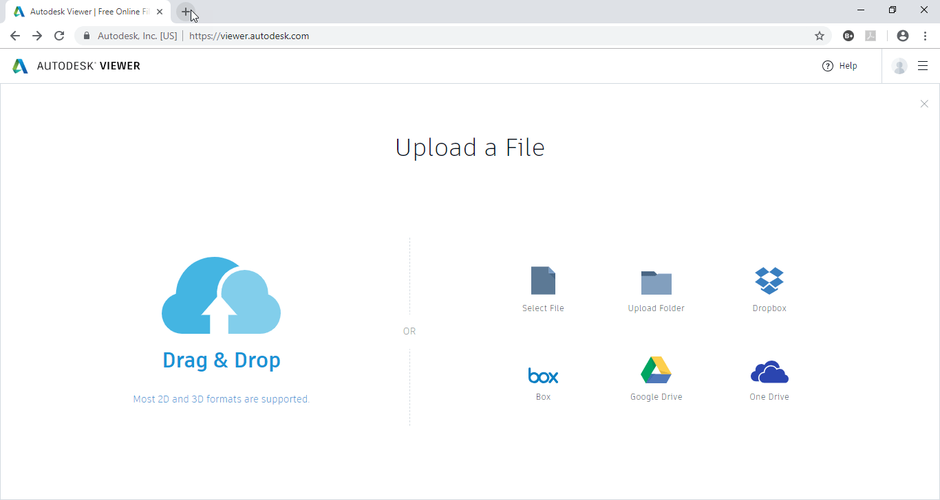
Did you know that Autodesk hosts a free Online Viewer that supports most of the Autodesk file formats? Simply browse to https://viewer.autodesk.com/ and sign in with your Autodesk ID (free to register)
While not all functionality is available that you’d expect from their native applications, the online viewer does boast support for an impressive 50+ files formats. For a full list of file formats supported, check out this Knowledge Base article…https://tinyurl.com/AutodeskOnlineViewer
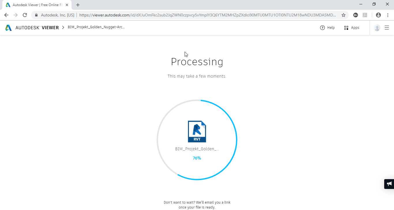
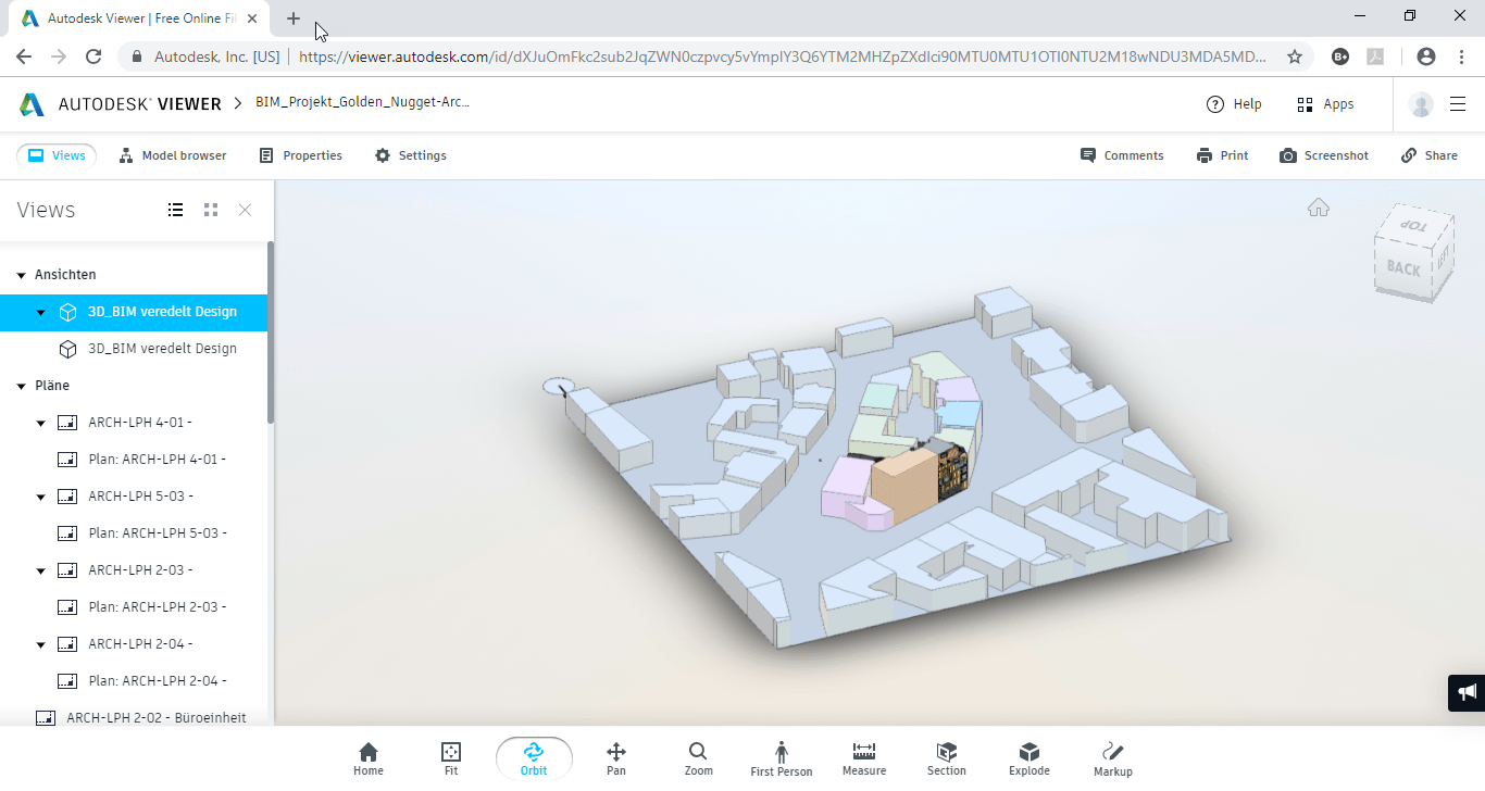
Wait for you file to be uploaded and processed. Or close the page after uploading and wait for the Email with a link to the model when it’s finished processing on Autodesk’s servers. Here’s a link to one of the Autodesk Revit samples models I uploaded… https://tinyurl.com/AutodeskOnlineViewerTestModel
While applicable to my career over a decade ago, I normally wouldn’t cover news on ArtCAM. It’s not relevant in my current professional life. However I find this interesting and noteworthy which is why it caught my eye.
ArtCAM History 101
In 2014, Autodesk acquired a CAM software developer named Delcam. (https://en.wikipedia.org/wiki/Delcam) Delcam was based in the United Kingdom and wasn’t as widely known as some of the big players like MasterCAM, Gibbs, Esprit or any number of others. Delcam was different. Instead of a few well selling products, they had a vast portfolio of CAM smaller solutions for niche markets like jewelry and footwear.
Autodesk on the other hand is a large volume software company. They don’t do “niche” very well. The smart play was to leave Delcam alone. This lasted for a few years but that recently ended.
One of their more popular products was ArtCAM. I supported it at one of my past employers over a decade ago. Earlier this year, Autodesk announced they were discontinuing ArtCAM to the dismay of it’s users. This was no surprise as Autodesk has a long history of acquiring software and companies and realigning or discontinuing products. You can see a list of most of them on Steve Johnson’s blog here…https://www.cadnauseam.com/autodesk-graveyard/
Departing from Historical Actions
What I do find noteworthy, and I’m just getting around to write about it now despite being month old news, is that they made the decision to sell it off. ArtCAM will continue but from a new company. This typically doesn’t happen. You either take the hit and migrate to what Autodesk wants or you find another product. This time, the product will continue but with a new company and name…Carveco. http://carveco.com/
Why do I find this interesting? It’s no surprise that Autodesk has pretty much abandoned new development of Fabrication CADmep, ESTmep and CAMduct. All their efforts are focused on Revit’s Fabrication parts. While that eliminates the need for CADmep for many, there’s still no clear public strategy on ESTmep or CAMduct. It would be nice if they took those products and found a way to spin them off. Granted, it’s harder in this case. They share a common data platform (the Fabrication Configuration) and content with Revit now. None the less, I’m sure there’s a lot of smaller firms that could make a good run of it. They’d just have to partner with Autodesk a little differently than in typical.
What do you say Autodesk CEO Andrew Anagnost? You’re company helped fracture the MEP industry with your purchase of MAP software in 2012. Only now do we see several 3rd parties emerging and targeting the MEP contractor. How about giving one or two of them a shot…to continue with the value we see in these products?
ActiveX is a framework developed by Microsoft in 1996 which adapts earlier concepts of COM (Component Object Model) and OLE (Object Linking and Embedding). Most people may think of this as Visual Basic (pre .Net era) programming.
This was supposed to fade away as Microsoft moved to the .Net based languages so Autodesk pulled support in the shipping versions of AutoCAD years ago. It was however still available as a separate download for a limited time but that time never arrived. Microsoft kept it around and still today, Autodesk supports VBA, a version of Visual Basic embedded within the Application over half a decade later.
If you’e not interested in programming AutoCAD in VB or VBA but do use AutoLISP, I’d encourage you to keep reading, this article is still for you.
Enabling VBA in AutoCAD
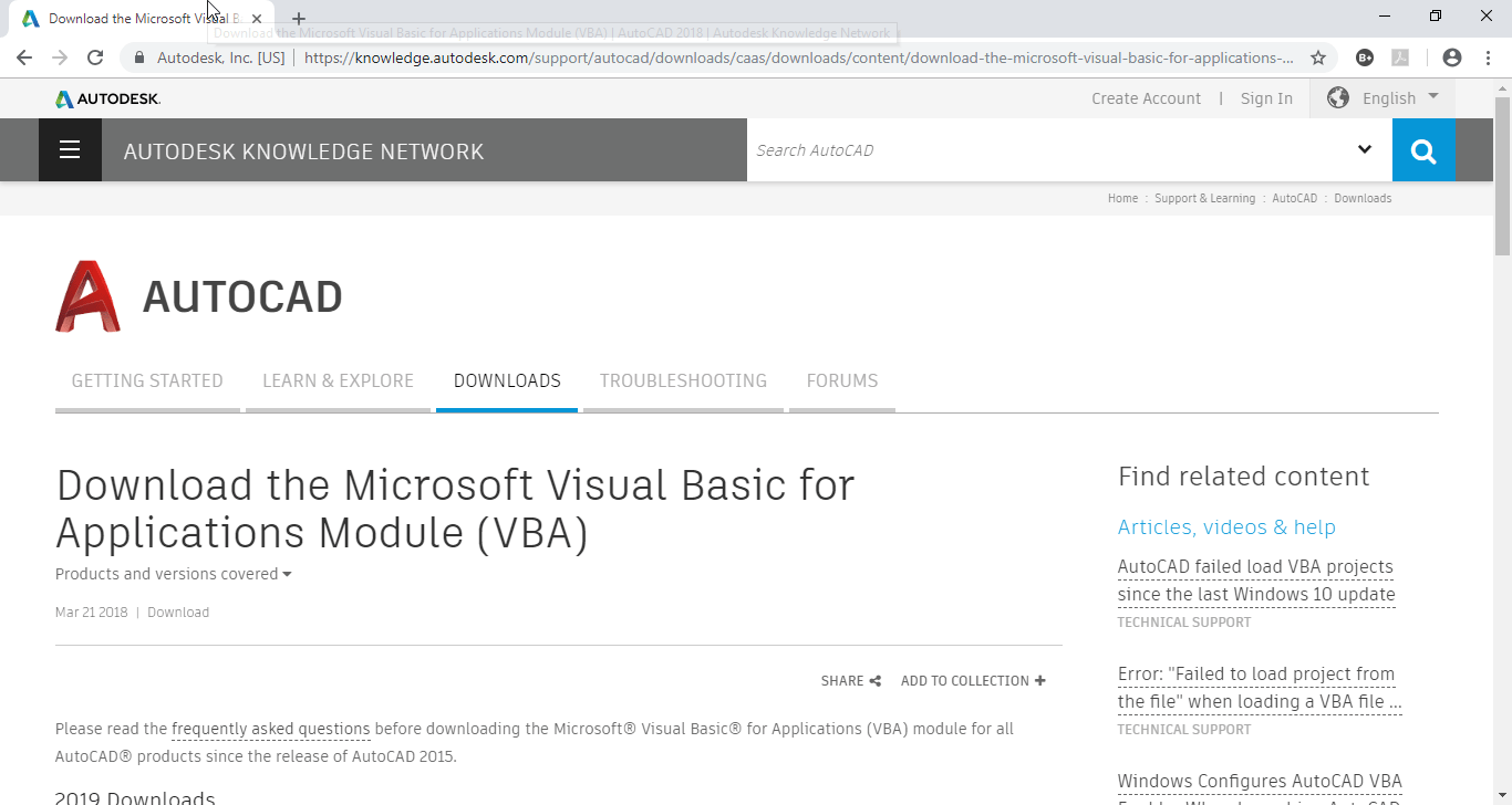
If you want to take a stab at VBA programming in AutoCAD, you’ll need to install the Visual Basic Extension. The extension can be downloaded for 2016 – 2019 versions of AutoCAD from this link….https://tinyurl.com/AcadVBAInstaller
Download the VBA Enabler for AutoCAD from Autodesk’s web site.
VBA Help for the AutoLISP Programmer
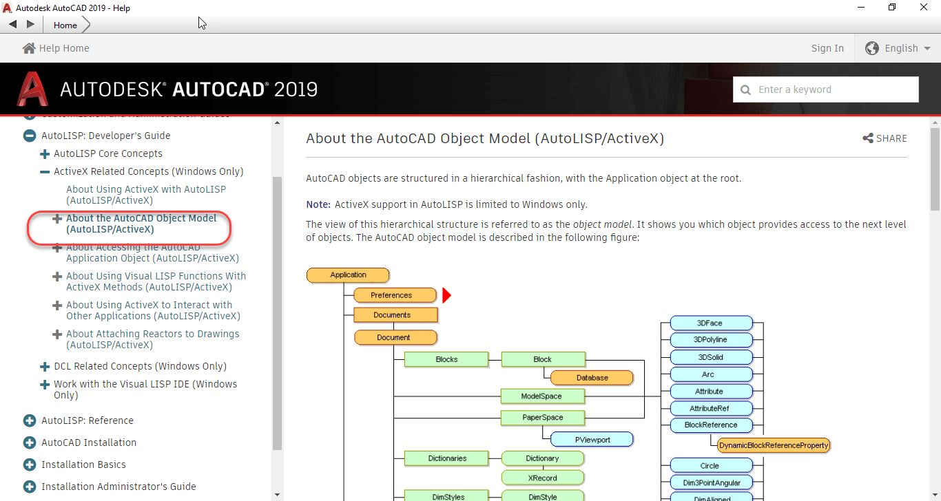
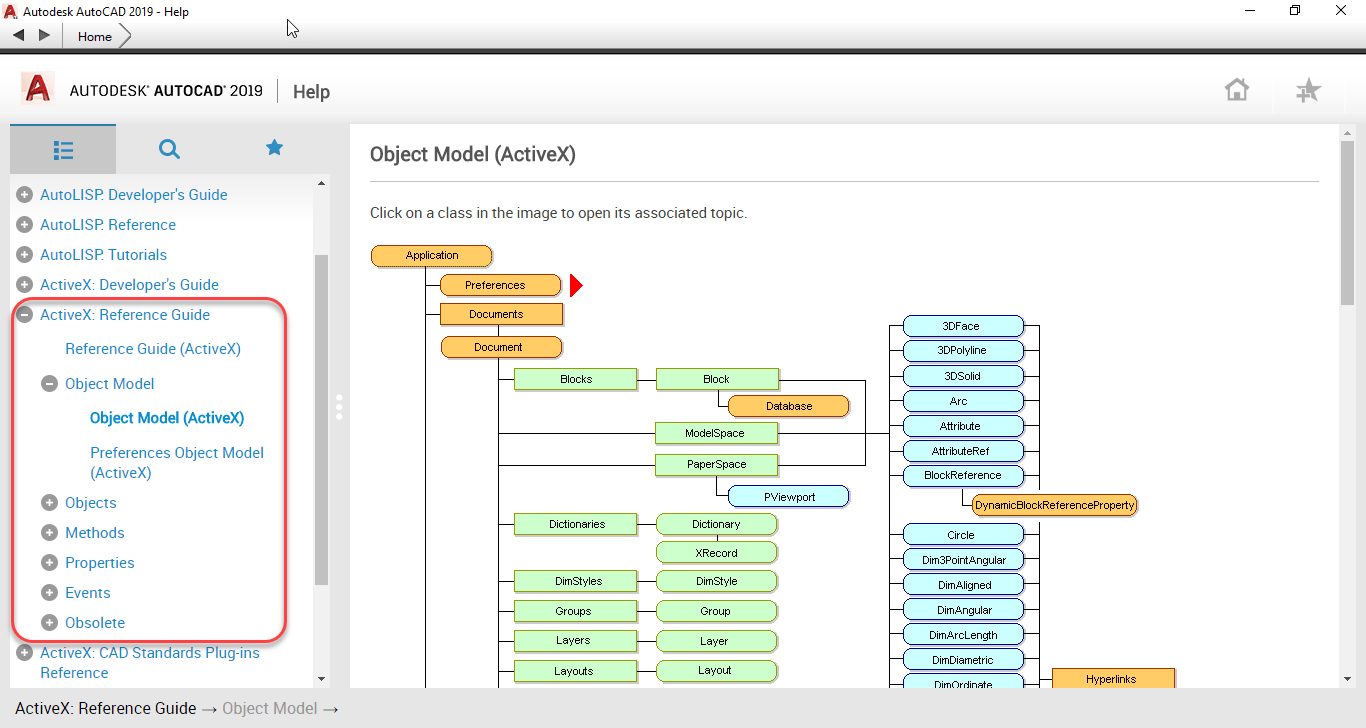
Now, with AutoCAD’s help now Online, you might be tempted to think that it’s the most robust help you can get from Autodesk. Simply typing “F1” will bring up AutoCAD’s help and browsing through the developer documentation, you can find documentation of AutoCAD’s ActiveX Object Model like seen in the following image.
AutoCAD’s ActiveX Object Model is buried in the AutoLISP documentation Online.
Looking at the above image, the graphic of the Object Model contains no hyperlinks. And there’s no documentation on the Methods, Properties and Events typically available for this type of programming.
If you’re programming in VBA, the VBA Editor has tools for helping navigate this model or provides a lot of Auto Complete functionality when typing code. This doesn’t help anyone trying to program ActiveX from AutoLISP.
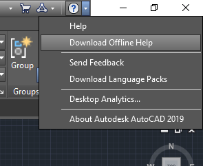
This is where the Offline Help comes in. You can access the OffLine Help download page from within AutoCAD by clicking the down arrow next to the question mark in the upper right corner of AutoCAD and then selecting Download Offline Help to download and install the help system.
Got to the Offline Help Download page from this menu.
You can also click the following link….https://tinyurl.com/Acad2019-OfflineHelp to go to the AutoCAD 2019 Offline Help download page as shown in the following image.
Download and Install Offline Help from this page.
Configuring Offline Help
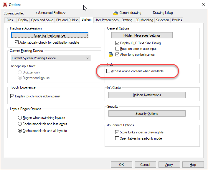
Once installed, you can configure AutoCAD to use the Offline version of Help by typing Options at the command line and clearing the toggle in the following image.
Clear this Toggle to Default AutoCAD to Offline Help
Once configured, typing “F1” will access the Offline help. One of several added pieces of Documentation which includes the ActiveX Developer’s Guide, is the ActiveX Reference Guide. You can see the graphic of the same Object Model documentation as before, but this one is hyperlinked to documentation of the Objects as well as lists all of the Methods, Properties and Events.
The ActiveX Reference Guide contain all the documentation you need for ActiveX programming.
While all of documentation is written with the Visual Basic programmer in mind, the organization of the ActiveX object model and everything else is where you can get all the documentation you need to help translate the function calls to their AutoLISP syntax. When you make a call to (vl-load-com) in AutoLISP, you have access to over 2000 additional AutoLISP functions with a VLR- prefix. These functions are all documented here in the ActiveX Reference Guide in Visual Basic syntax.
In a future post, I’ll explain how to translate the Visual Basic documentation to AutoLISP syntax. If you don’t want to wait, review the ActiveX documentation found in the AutoLISP developer guides…it’s all in there!
One Final Note: You do NOT need to install the VBA Extensions in order to program w/ActiveX from AutoLISP. Just install with Offline Help and you’ll have everything you need.
It’s been a couple weeks since Autodesk University so I thought I’d reflect and recap some of my thoughts.
For starters, I don’t often toot my own horn but I was right. 5 Months ago, one of Autodesk’s Technical Marketing Manager’s posted to LinkedIn how Autodesk University was “Joining forces” with the MEP and Structural Fabricators be eliminating the Monday MEP & Structural Fabricator’s Forum Monday pre-conference with the rest of Autodesk University and replacing it with the “Connect and Construct” pre-conference.
I commented then that this was marketing spin, that there would be less focus on Autodesk Fabrication. I was right. I typically run into 120-130 people every year at Autodesk University. This year I don’t think I broke 80. I’d say only 10% of the MEP contractors I typically run into were there this year. As expected, there were many less Autodesk Fabrication sessions and a lot more BIM360 sales pitches.
You can read the original LinkedIn post and my comment here. It did get me a private Email from Autodesk asking why I was negative toward the event that I was speaking at. As I told them, I’m not negative, but I do feel obligated to correct misconceptions they’re spreading. My industry peers are expecting Fabrication technical content as they’d received in the past and they weren’t getting it this year. Most elected to go to Applied Software’s MEP Force conference instead or skip all together.
There were some compelling keynotes from what I heard (I skip most, too crowded and I can watch online after if I hear they were good), but if you’re a larger progressive MEP contractor, you really didn’t learn a lot from the Connect and Construct summit IMO. They still are trying to tell people that BIM is something we should be doing and we should be using BIM360 this or that. A lot of promises of what the future holds…mining intelligence from your models. I couldn’t help but think…”We had that with Autodesk Fabrication but you broke it by not finishing Revit’s Fabrication Parts and stopping development of CADmep, ESTmep and CAMduct.
Overall, I think the week as a whole was better than last year. I skipped many of my scheduled classes as I was busy talking with others in hallway conversations. This is really why I go and where I get the most value.
If you’re interested in reviewing any of the material presented at Autodesk University, all the 2018 sessions are now online at this link.
Key Takeaways
Seems to be a lot of 3rd party activity in the MEP contractor space finally after Autodesk’s acquisition of MAP fractured the market. Both GTP’s Stratus product and FabPro1 are making some compelling workflow applications. I’m also aware of about 5 or 6 different Revit based spooling tools either released or nearing release.
Biggest issue for 3rd parties in the MEP contractors space….Autodesk’s lack of enhancing the underlying Fabrication platform. They’e laid off anyone that knows what we need and why…only 4 programmers remain from the original MAP team rumor has it. Most of the 3rd parties have larger teams focused on MEP than Autodesk does now.
Seems to be some increasing acknowledgment by Autodesk that they screwed up a bit with the MEP contractors. It remains to be seen if they do anything about it. There’s several things in play that I can’t speak to (NDA) but I remain hopeful at some point things will start moving again.
Seems to me more people looking to get into the ITM content space. Iv’e had so many conversations I can’t recall what I can and can’t say so I won’t go into details. We’ll see how it goes….it’s a tough platform as the content is not agnostic and highly dependent on each company’s configuration. Recall what I said about 3rd parties hampered by Autodesk not enhancing the Fabrication platform? This is a perfect example.
Outside of the MEP Fabrication world, lot of talk about automation. Hailing from Manufacturing myself, I’ve seen parallels coming for years. Manufacturing leads construction by 10-20 years in just about everything…Parametric modeling, Lean, Product LifeCycle Management (Mfg’s “BIM”). Nice to finally see after spending most of my career working for Manufacturers of construction products and not working for a construction firm manufacturing.
Most striking takeaway….the large volume of contractors employing their own programmers. One General Contractor of about 3000 employees had 10 full time programmers. And it’s not limited to GC’s….a lot of my peers in larger MEP contractors have full time programmers. I suspect this trend will continue as Autodesk is moving too slow and the data each firm really needs is highly unique to their blended data (in and out of BIM).
Forge Devcon (formerly Dev Days) was interesting. The Monday developer conference Dev Days was always my highlight of AU. Then others started piggy backing onto Monday…Conceptual Design Forum, MEP Fab Forum, etc. Working in MEP I had to attend. While I’m disappointed the MEP Fab Forum went away, I’m also glad as I was able to attend some Forge Devcon sessions. That reminds me, I need to start getting back into development.
Less technical and more “Whitepaper” or “Customer Stories” than ever. Seems like a lot more sessions showing you what people are doing but not how they are doing it. Maybe this is what people really want but I really miss some of the hard core technical content you use to get. It’s still there but in less quantities….or I’m just bad at selecting sessions to attend.
Not sure I’ll speak again after over a decade of doing so. There’s less technical sessions…I prefer doing those as opposed to the philosophical “here’s how BIM should work” type of classes. The products our industry needs and uses Autodesk doesn’t promote and they audience is just not there. I could talk about Revit but it’s the same as it was last year with minor improvements. Nothing that would fill a 60 minute session unless I wanted to show all the 3rd party tools and custom code you need to write to finish where they left off. I’ll likely submit a few proposals next year anyway. We’ll see where it goes.
This doesn’t really seem like a surprise. PlanGrid has a large and active user base where as competitor Fieldwire seems like they’ve had trouble competing and gaining significant market traction.
What is a surprise to me, is that typically these types of “big” announcements are typically given in Las Vegas during Autodesk University, not the week following. I suspect that in this case, an announcement of this type would have distracted from the other BIM360 related messaging Autodesk was trying to deliver.
Why Would PlanGrid Sell?
What made PlanGrid strong in the market is the ease of use and field adoption of their platform. Plain and simple, field personnel liked it and used it, It doesn’t really matter what something costs if it doesn’t get used. PlanGrid had a platform that was used. My guess is they sold because what better way to finish than on top. In the end, what were they doing that Autodesk couldn’t do, or soon do with their BIM360 Docs platform? I know several companies that pay more annually for PlanGrid than their entire Autodesk product lines. In some cases PlanGrid renewals were double Autodesk. And for what? Storage and viewing?
As Autodesk continues to build out their BIM360 platforms, and users increasingly adopt services like BIM360 Design (formerly Collaboration for Revit), it wouldn’t take long before people started asking why they were paying so much when BIM360 Design published to BIM360 Docs already and seemingly did the same thing?
Where would PlanGrid differentiate itself? When we take an intelligent model and publish it to a PDF, we’re loosing a lot of information. Any more intelligence PlanGrid would try to add is attempting to recreate what was once there but lost. Not to mention, adding more functionality would start to move PlanGrid away from the core principals that made it strong…simplicity. In the end, I think PlanGrid chose to end on a high note before an eventual decline.
What Does This Mean For Autodesk?
When Autodesk acquires a company, they do it for one or more of the following reasons…
Buy interesting technology they don’t have
Buy the talent of the firm who’s doing interesting things and employ them to do the same for Autodesk
Kill technology that’s driving the market in directions Autodesk doesn’t like
Buy the customers
For Autodesk, I don’t really think they care about PlanGrid’s technology or development teams. Not that they aren’t good tools and people, but Autodesk has their own. Instead of having to OCR PDF’s to automatically hyperlink them, you should be able to create the PDF from this intelligence already in Revit. There’s really no point in trying to recreate lost intelligence (PlanGrid) when you already have it captured (BIM360).
Instead, I think Autodesk wanted the user’s. It’s the quickest way to increase your BIM360 Docs usage which is where I think the users will be migrated to. If not BIM360 Docs, perhaps a more streamlined tool for field communication that uses BIM360 Docs as it’s storage platform.
What Does This Mean For Users?
Lower software costs. I know, I know. They’s not something you typically get from an Autodesk acquisition but paying double for a PDF sharing platform than all your other Autodesk services certainly won’t continue. I predict the price will drop, they’ll then “realign” duplicate platforms and move everyone to BIM360 because PlanGrid no longer “makes money” and they’re done. That’s what happened in the past in similar situations like Autodesk Fabrication being acquired from MAP software. We in the MEP world know how that worked out…new development halted, fixes released at a glacial pace and updates almost non-existent. Move to Revit or fall behind. I think you’ll see that dynamic play out w/PlanGrid as well.
For now, I’ll enjoy not paying double to share PDF’s because PlanGrid says we have tens of thousands of sheets on a project we use when the reality is we’re only looking and a handful of sheets for a project team that’s using PlanGrid. While a good product which we do use, our usage numbers have never been what they’ve suggested. I wonder if Autodesk fell prey to some of those technically accurate but misleading usage stats as well.
This warrants a little explanation. Many companies have multiple locations and need to sync Fabrication configurations between those sites. Other companies have their Fabrication configuration copied locally to the users system from a central network location.
To keep from having to manually keep different sites or local computers up to date, it’s natural to look so some of the many technology solutions like Microsoft’s One Drive, Box.net, Dropbox, Google Drive, DFS Replication etc.
Here’s the problem….most of these solutions sync files in their own order and time frame. You often can’t control when they sync. When using CADmep, ESTmep or CAMduct, just using the software can cause the program to read back from the database files. Many of the database files reference each other using indexes. Take for example, the Specifications and Materials….both of those database areas refer to each other.
When changes are made, what happens is the files get updated where you make the changes, but the two files that get changed, may sync somewhere else at different times. As you’re using the software, if it happens to reread some of the database files when some are sync’d and others aren’t, this can cause unspecified problems.
One of the more common issues is when a system you’ve drawn changes to a completely different system. Have you ever had a Cast Iron No-Hub waste line all of the sudden day it’s Supply Air 2″ Positing Water Gauge? This is our of sync syncing issues is often the result.
How do you work around this? Try to find sync solutions that allow more control, like after hours sync. I personally like an old batch file running RoboCopy as it allows a lot of control and I can have it fire up when the user logs on. They can also manually run it during the day if I push our a critical update otherwise the get the update tomorrow when they log in. When syncing servers from different sites, I schedule it to run after hours.
This issue is most common w/CADmep, ESTmep and CAMduct. Because Revit loads and stores your services, it doesn’t read back to the database unless you explicitly tell it to reload the services so it’s risk is greatly reduced to the point where I wouldn’t worry about it.
Now, there are people that are doing local Sync’s in real time. My prior firm, we had some…let say…”creative folks” who would take liberties with the database if they knew it was local. As such, I used Windows OffLine Files to sync a local copy but make it look like it’s still on line. This is a Sync’d local copy and goes against what I recommend above. However, we forced it to rescan frequently so when there were changes, they were small, just a few files and they’d sync quickly about the same time. Larger changes involving a lot of files can open up your risk window to having issues.
If you’re going to use life syncing utilities, proceed carefully and watch for unexplained issues. Making large changes after hours and smaller changing during working hours can help.
And if you’re considering using Window’s Offline Files, prepare for a long learning curve and experiment with yourself first. Offline Files have little control from the User Interface and is best managed with Group Policy.
If you’re an AutoLISP programmer and use Autodesk Fabrication CADmep, you most likely know that there’s a COD Scripting language in Autodesk Fabrication that provides read and/or write access to CADmep properties. The problem with COD Scripts, is that sometimes they’re not powerful enough to do all of the other things you’d like to do and you may want to use AutoLISP.
What you may not know is that you can access the vast majority of CADmep properties from AutoLISP. To so this, you need to configure CADmep’s List Setup dialog which will provide a light weight but similar interface to what you see when you build reports in Autodesk Fabrication.
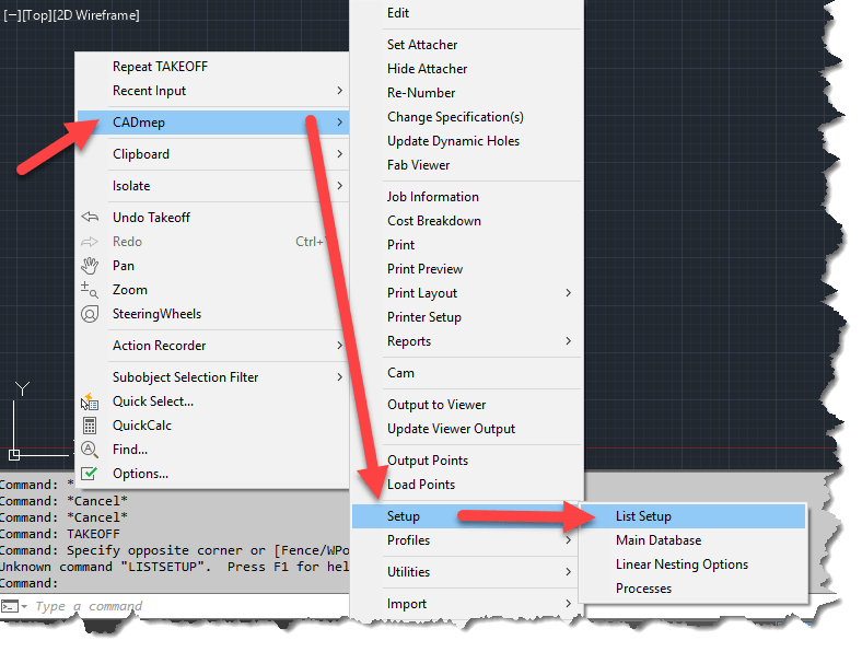
To access List Setup, right-click in an open area or the drawing editor and then select “CADmep” -> “Setup” -> “List Setup” from the menu.
ListSetup will Provide access to CADmep Properties
Configuring List Setup will provide access to the configured properties via DXF codes which are one of the most common ways of accessing object properties in AutoLISP. (You can also access these same DXF based properties via VBA, ARX or .Net)
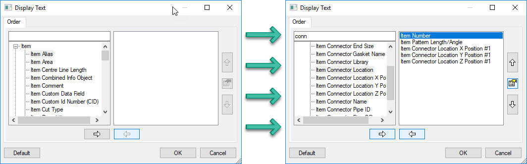
The following image shows the List Setup dialog before (left) and after (right) being configured. Simply add the properties you want to extract in the order you want them.
Before and After Configuration of List Setup
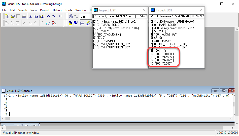
Once you’ve configured the properties you want, a simple call to the (ENTGET) function in AutoLISP will return the data you’re looking for. You can see in the following image, that we’ve saved the DXF data to two different variables in the VisualLISP editor. The listsetup-blank variable (left) was done before configuration and the listsetup-config variable (right) was done after the configuration of List Setup.
CADmep Properties can be Found in the 300 DXF Group Codes
The code used to extract the data is the following….
Because the VisualLISP editor does not word wrap it’s results, you can use the Inspect
Now, there are a few things to know about this method….
All CADmep properties show up in DXF Group Code 300. If you are returning multiple properties, you’ll have multiple 300 codes to parse through.
The order the properties are configured in List Setup is the order the properties will appear when returned in AutoLISP. There really is no other foolproof way of knowing which codes are which properties (unless obvious by their value) without knowing the order List Setup was configured.
If you later change the properties or their order, you’ll likely break your existing code. Think carefully about what you may want later and add it from the start even if you don’t want it at this time. If you need to add properties later, simply add them to the end of the list.
This method works well for reading Fabrication properties. It doesn’t allow you to set them using functions like “(ENTMOD)” or “(ENTUPD)“
After a very brief appearance toward the end of October, the Fabrication updates for 2018.3 and 2019.1 are back on line as of today.
Unlike previously speculated, they were not removed due to issues. They were intended to be released later but were inadvertently released early. If you happened to have them from their initial release, you don’t need to download the update again, the build numbers did not change. However, the PDF documentation of fixed issues on some of them did get more information listed in what was fixed. You can review all the issues addressed here…
In CADmep, using the Size command, you can tag the size of a fitting. But on a fitting like a transition, what if you wanted to tag the size of the opposite end?
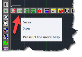
This can be easily done but the sequence is a little nuanced. Type “SIZE” from AutoCAD’s command prompt or select the “Size” tool button on the CADmep toolbar.
When prompted to Select Objects, select the fitting. Once the fitting is selected, instead of pressing <Enter> to end the selection like you normally would, press and hold the <TAB> key while you press the <Enter> on the keyboard at the same time. Your tag will display the size of the opposite end.
Depending on your AutoCAD and Mouse settings, right-clicking to end the select objects prompt may not work and instead bring up a right-click menu. For this reason, it’s recommended you use the <Enter> key on your keyboard while pressing <Tab>
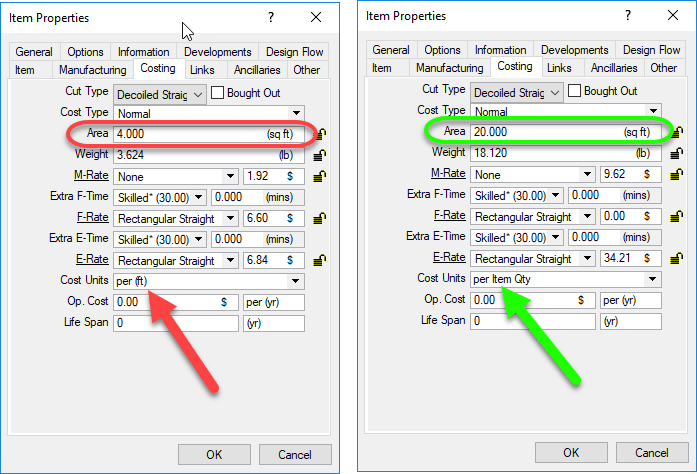
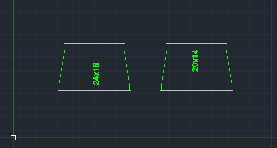
The following video shows to transitions of the same size side by side. The left transition has it’s size tagged like you normally would. The fitting on the right, the <Tab> key his being held down when the <Enter> key is pressed which results in the tag displaying the size of the opposite end of the fitting.