Construction’s Misguided ‘Model Based’ Ideology
Paraphrasing Country singer Johnny Paycheck, “Take this Model and Shove It.”
Yes. You heard me correctly. But just to be sure, let me rephrase it another way….”F_ck the Model“.
There. That should do it.
That may seem a bit of an odd thing to say. Especially for someone like me. After all, I’ve spent most of my career working with technology in Manufacturing and Construction. It’s been good to my family and I. But like many things, it can go too far. And it has. It’s time someone stands up and says something.
Why Do You Oppose 3d Models?
Why am I opposed to 3d models? Simply put, I’m not.
I’m opposed to idealistic visions of a utopia where everything can be solved with a 3d model. That may be the case one day, but it won’t be in my lifetime. Technology moves fast. But we’re also a long way off from promises made even a mere decade ago. The value of creating many 3d models does not overcome the cost to generate them (or maintain them).
There’s a lot of reasons NOT to model things. I won’t elaborate too deeply here. You’ll either get it or you won’t. But to summarize, here’s some of the major reasons to NOT 3d model something…
- No time / schedule
- No resources / staff
- Lacking tools / technology
- Less efficient / takes longer
- No value / creates waste
If you disagree and think we should 3d model everything…like right now today, consider you might be part of the problem.
The 3d Model Vision
There’s a lot of folks who tell you how things “should be”. Digital Twin this and that. Everything will have a perfectly pristine working digital clone. Identical in every detail.
For the most part, I agree with them. However there’s an economic ecosystem at play. It’s beyond the control of a mere few wishful thinkers and prognosticators. It takes a while to turn around an industrial complex the size of constructon. So until modeling everything adds value offsetting it’s cost, some things (many things) should never be modeled. Ever.
Some will say this is because the industry full of laggards. Those reluctant to change. But look around. The skyscrapers, the roads and bridges, the dams and monuments. Do they look like they were constructed by laggards? Next time you’re in a big city, walk up to a construction worker and call them a laggard. See how that goes for you.
It’s also important to keep in mind how things “are” didn’t just happen in an ignorance vacuum. Things evolved for a reason. And until those reasons go away, we’re left with what “is” not “what should be”. And if things haven’t changed as you expected, consider the problem might by more complex than you give it credit. Those ‘laggards’ as they’re called, just might know something you don’t.
Resistance to Overboard
3d Modeling in manufacturing preceded common use in construction by about two decades. Same with concepts like PLM which is manufacturing’s ‘BIM’. Lean? Started in manufacturing (Just like me).
I pushed hard for 3d modeling back in one of my old companies. Endured the eye rolls and comments about how “3d is for boxes, not complex things like the warped surfaces” which they were doing in 2d AutoCAD. I also promoted Revit for a manufacturer of construction materials before Autodesk acquired the technology.
In each of those cases, when they finally saw what I was trying to convey, they over reacted and went too far. Complete abandonment of all 2d even where it made sense and 3d had no added value. They even attempted to do manufactured piece part modeling in Revit where Inventor or Solidworks was better suited. What was need was nuance and a blended approach. Instead the result was a binary shift. Classic throwing the baby out with the bath water. Lessons learned the hard way.
Sometimes when you apply too much force to a seemingly immovable or stuck object, it’ll eventually break free and go beyond it’s acceptable tolerance. If you’ve ever busted a knuckle trying to remove a stuck bolt while working on your car, you know what I mean.
3d Modeling has went that same way. Gone too far. If you ask me, as an industry are suffering from bruised, broken and bleeding knuckles.
The Problem With 3d Models
So what’s wrong with the current 3d modeling approach? Absolutely Everything.
No, not THAT ‘Everything’. There’s a lot of 3d modeling that creates incredible value and eliminates waste. It greatly exposes risk before cost is incured. In those cases we should do more not less.
The ‘Everything’ I’m talking about is that we’ve somehow moved into this unattainable, low intellect thinking that 3d modeling is the answer for….well, just about EVERYTHING. Revit projects have become nothing more than an erotic orgy of data vomit.
Oh look…corn. I don’t remember having corn. Is that a piece of baked potato? A date dump from a 3d model often results in forensics to even determine what the hell it is.
- Need data? Add it to the model.
- Nothing modeled? Model it.
- Data changed? Open the Model and edit it.
Somehow the 3d Model turned into not only the single-source of truth but the ONLY source of truth. Merit for what to put in a model is typically controlled by somone with limited perspective. Can the computer can open it, navigate efficenetly and display/print sheets in an asthetically pleasing way? That’s the benchmark used today. There’s not a shred of data lifecycle cost or maintenance perspective let alone the cost and impact of those decisions up and down stream from the model.
This is absolutely flawed thinking. When you look at the data required for the built environment, there literally is no commercially available applications on the market today to help you manage this data. Hardly at the project level, and certainly not at the enterprise level. None. They’re all focused on the project model at it’s core….not project data. And certainly not enterprise data.
Yes, there are applications that help you manage portions of data or small genres of data. But nothing exists today which allows a company to manage their AEC ‘Data’ and leverage it across the enterprise. Once again I repeat, NOTHING.
Baseless Claim or Reality?
I’ve been thinking along these lines for some time. Years perhaps. I’ve been in User Groups and Meetups. Vendor Webinars. Industry Conferences. Hallway conversations. Far too many times I’ve heard “Model it” or ‘Add it to the Model”. No debate. No discussion. Just an accepted fact without any hint of value focused thought.
There’s a lot of examples in other industries that suggest alternate thinking. One is Manufacturing which typically leads trends in constriction by a couple decades. Manufacturing has Data Management systems and PLM (Product Lifecycle Management) systems. These are database systems that manage not only models but the data about the models. The key is that the data is associated to the model from an external database. They typically contain a lot of data that isn’t modeled. Anyone model Grease or Paint? A well implemented PLM system will tell you exactly how much you need and where to procure it all without a model of it.
Another notable example is GIS (Geographic Information Systems). A database is at it’s core, not CAD data. CAD data is merely just a small subset of data in a GIS system. Imagine a home changes owners. How does someone at the County get their GIS system updated? They update a database. What aren’t they doing? Opening CAD…Editing a graphical polygon with the owner information and saving the CAD file.
In both of these cases, external databases are linked to and help manage graphical models. The models don’t contain all of the data. And the databases usually contain MORE than just data for the models themselves. Unlike construction where we try to embed every conceivable piece of information right into the model itself.
I’m Not Alone…Anymore
As I said earlier, I’ve been thinking about this for a while. I frequently question my own sanity. Perhaps not as much as those who know me. But I do none the less. So imgine my surprise when I recently came across a couple articles that reaffirmed my thoughts.
This first is this article from AEC Magazine. ‘BIM is Bust’.
https://aecmag.com/opinion/bim-is-bust-how-should-aec-data-work-hok/
The next is the ‘Data Centric Manifesto’. You can read that here…
http://datacentricmanifesto.org/need/
To summarize, enterprise data is locked inside applications (and models). It’s created there and those applications serve as the gate keeper. Yes there’s Cloud services with API’s. But the data they host and control is still application/model centric. It doesn’t integrate with your data. If you want the data, you have to integrate with it. As such, it’s application/model centric. Not enterprise centric.
How Should We Use Models?
By examining how modeling tools came to be, we can understand how those tools should be used,
That start was as a drafting and documentation tool. At it’s core, creating drawings is the act of working out design decisions and documenting them. That documentation is then used to physically build whatever it is you were designing.
As tools progressed, they offered some natural enhancements. 3d helped us visualize not just during the design process but for others who weren’t skilled at visualizing in 3d from a 2d document. Parametric functionality also helped us build smart objects which helped us quickly make derivative designs. These functions also helped increase efficiency in the design process. We lessened the need to calculate small details and merely used smart objects to help build a design. They’re really ‘Digital Pre-Fabrication’.
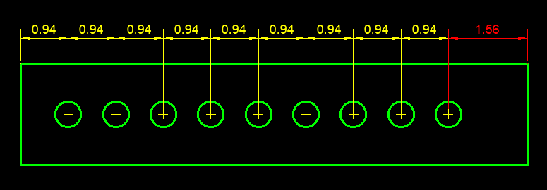
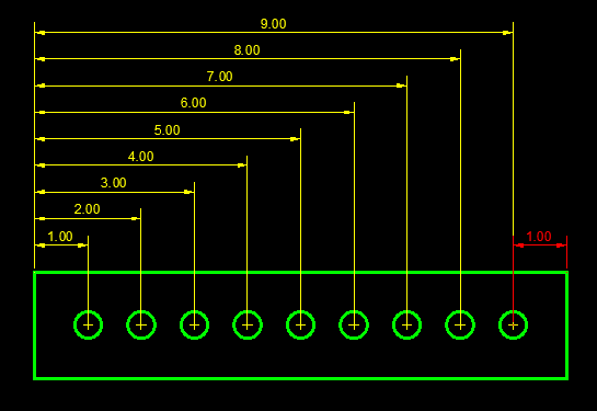
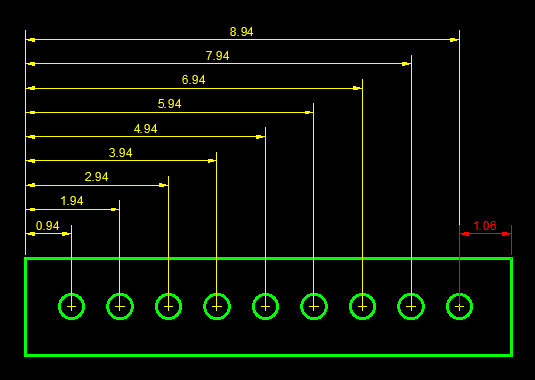
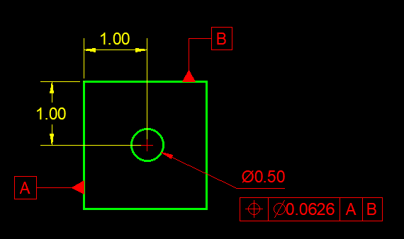
Here’s one example: The following image is a conveyor support. It’s top and bottom width are variable. So is it’s height and the number of cross bracing panels.
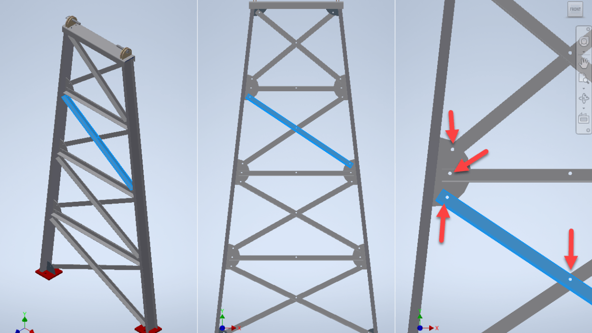
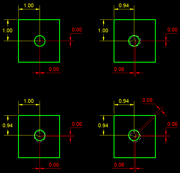
Now look at the holes on the half circular mounting plate. Look also at the holes where the cross-bracing meets. It’s not in the center. What’s the length of that steel angle anyway?
Imagine trying to calculate all of this information from purely numerical data and no geometry. It’s no small task. The number of right-triangles and trigonometry required is quite complex.
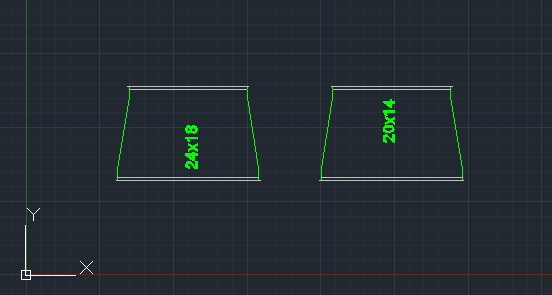
If you need to build a few of these, 3d modeling is the perfect fit. The smart objects have made it a digital measuring tool. But what if you fabricated thousands of these? All different. Copying design files and making derivatives with new sizes gets to be time consuming. And the same 5 or 6 inputs drive all of them. And eventually, some of the parts will likely be duplicate as parts from one design just “happen” to match another. And what if the design needs to change? All those models as opposed to just regenerating them.
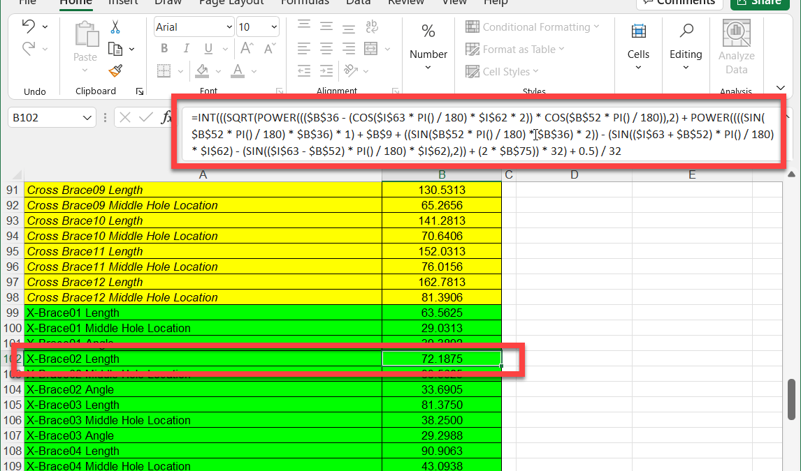
If you wanted to build a manufacturing system around this, you need a configurator and move data OUTSIDE the model. In this case, that’s what was done.
The assembly is 100% parametrically controlled from a spreadsheet. ALL data driving the model is driven from Excel from 6 inputs. From the length of the angle and position of holes. Even the size and shape of the structural steel shapes is driven from Excel. Here’s the formula for just the length of the selected cross-brace…
So what type of software tools do we have to manage this data at the enterprise level? Sure there’s product configurators but what about you parts library? Historical models and drawings? Common reference data defining shapes and configurations? Vendors and pricing? That’s where you implement data management or PLM systems in manufacturing.
What do we do with that data in Construction? Embed it in a model. Editable only by a Revit/AutoCAD/Microstation user. Locked up and application/model centric.
If you ask me, the solution was obvious. Or so I thought.
The Solution Should be Obvious
One of our technology vendors was pushed hard from many customers like us. The ask was to handle non-model based workflows and data. Their solution? A tool to model data in the field. They built some cool tech that will be helpful in cases, it’s not what was needed or asked. The data wasn’t modeled for a reason. So we didn’t need another tool to model it.
The real solution is to build a tool that can help us manufacture and build from data. No model required. Cutting of linear materials requires very little data as an example. Other operations like purchasing or assembly can be accomplished without a model too. Which means we can procure, manage pricing and labor, and even manufacture vast amounts of parts and data all without a model. None.
If we had tools that let us build WITHOUT a model, then where a model IS required it’s very simple to generate a model and/or link a model to that data. The manufacturing and construction process would have 100% coverage because it’s based on data, not a model.
When you use a model based system, you have partial coverage. You miss all non-modeled work and introduce a second workflow and processes. Also lost are analytics to view your entire operation.
One company I know literally publishes purchased items like buckets of adhesive as generic models. This is done so they can have all work go through their “model based” system and link to an ERP. Is that really what you want? It’s yet another workaround to compensate for lacking tools.
To summarize…
If you build tools that work only with models, they’ll only work with a model.
If you build tools that work with only data, they can also use models because a model is a shortut to data.
Now all we need is someone to start building “Data” centric tools.