Back in the day, I briefly worked for an Autodesk reseller. This particular reseller was classified as an “Education Reseller”. In short, this meant they were one of a few resellers that sold Autodesk products into the educational market (high schools, universities etc.).
As you can imagine, a school would likely have most of not all the products. Back then, Autodesk provided a complete list of all the products and their recommended install order. Fast forward to today, they’ve either gotten incredibly lazy or in all their massive layoffs over the years, the domain knowledge is gone. I suspect both.
Autodesk’s Recommendation
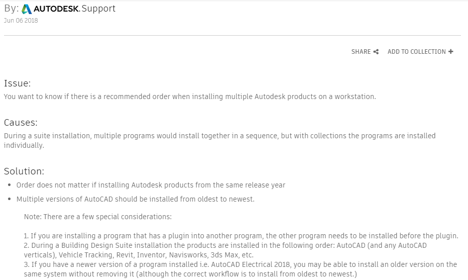
Take a look at Autodesk’s current recommended install order from this link. which was last updated 6/6/2018 at the time of this writing. In the event the link changes, here’s what they say…
What’s wrong is that they tell you within the same product year, the install order doesn’t matter. This is outright false for many reasons. They try to note a couple “exceptions” stating that if there’s any add-ins, the base product should be installed first. But which products have add-ins to what other products?
CADmep is obviously running on top of AutoCAD so AutoCAD should be installed first. That seems obvious. But Navis also installs Exporters depending which products it finds and it doesn’t always show up in an Add-ins tab. So this is less obvious. Buy there’s also other dependencies that are even more obscure. Should you install Revit or Inventor? Should either go before or after 3ds Max? This is less obvious to most users.
This is really why someone would ask that question. It’s a real dis-service then to start out telling them it doesn’t matter. In fact, it matters most of the time, and it doesn’t matter as the “Special consideration”.
Determining The Real Install Order
There’s a few ways to handle this. If you’ve been around a while and had one of the old “Design Suites”, install in the same order as the Design Suite did. But note that this did change between product years and types of Suites. Plant Deign Suite 2013 for instance installed Autodesk before Revit where as Building Design Suite 2016 installed Revit before AutoCAD.
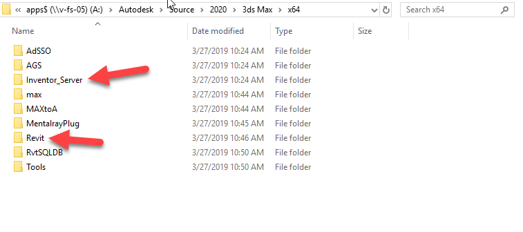
One of the other ways is to look at the install media folders to see if you can find any dependencies. Take for example 3ds Max. Look in the x86 or x64 folders and you’ll see references to Revit and Inventor.
This means we should install Revit and Inventor before installing 3ds Max. But what if we’re using both Inventor and Revit? Which of those goes first?
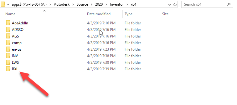
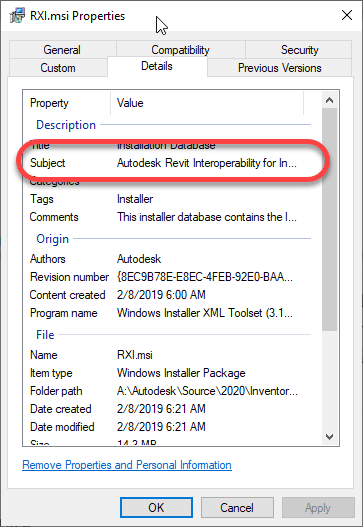
You’ll see the RXI folder in the install files. Hard to tell what it is. When you drill into the folder, there’s just a single MSI. If you right-click on it and select Properties and do to the Details tab, you can see it’s Revit Interoperability for Revit. Other folders deeper in the structure also confirm this by their naming,
Based on this findings, it suggests installing Revit first so Inventor can see it and install the Interoperability tools.
Here’s My Order
So, if you’re an Autodesk Fabrication user, here’s what I typically do (and why)….
Revit(doesn’t seem to depend on anything else)
AutoCAD(I can’t find a dependency for AutoCAD. But anything with an Object Enabler will want it here and it’s a core product so as a matter of safety, I install it early just in case)
AutoCAD based Verticals like MEP, Arch, etc.(These use AutoCAD as its core. I’ve not checked dependencies between verticals but it’s likely safe to install them in any order. I usually do Arch first if I’m going to include it as MEP is built on top of Arch but it’s really not needed as MEP installs what it needs)
Inventor(because of the Revit dependency covered earlier)
3ds Max (because of the Revit/Inventor dependencies)
Navis – Freedom/Simulate/Manage(Navis exporters only install for products already installed so we install this toward the end)
Fabrication CADmep(allows CADmep Object Enablers to install for Acad, Navis, etc.)
Fabrication – EST/CAM/etc.(order doesn’t matter)
If there’s anything on the list you don’t use, just skip it. If you happen to install Navis before some of the dependent products, just use “Add/Remove Programs” in Windows Control Panel to modify the install to include new exporters or download the Exporter installs separately from Autodesk’s web site.
Under the resources menu for Autodesk Fabrication, the COD Scripting section has been updated. This now points to another sub-menu of additional COD Scripting reference information.
The link to the COD scripting libraries has also moved one level deeper so if you have a bookmark and it comes up blank, you many need to re-link it.
I still have more information to add that I’ve not previously documented. These are more advanced functions or other undocumented functions. I’ll post notices as I update them.
You can find the additional COD Scripting information compiled here. Direct links to all the scripting reference information is below…
Resource information for Autodesk Fabrication has been updated. They now include information on the 2020 version of CADmep, ESTmep and CAMduct. In short, nothing has changed.
The FabViewer Command Reference did have one new command added. However, this was not new to the 2020 version. The CADmep 2019.1 update added a command which was missed previously.
Don’t use Ancillaries with Breakpoints inside an Ancillary Kit.
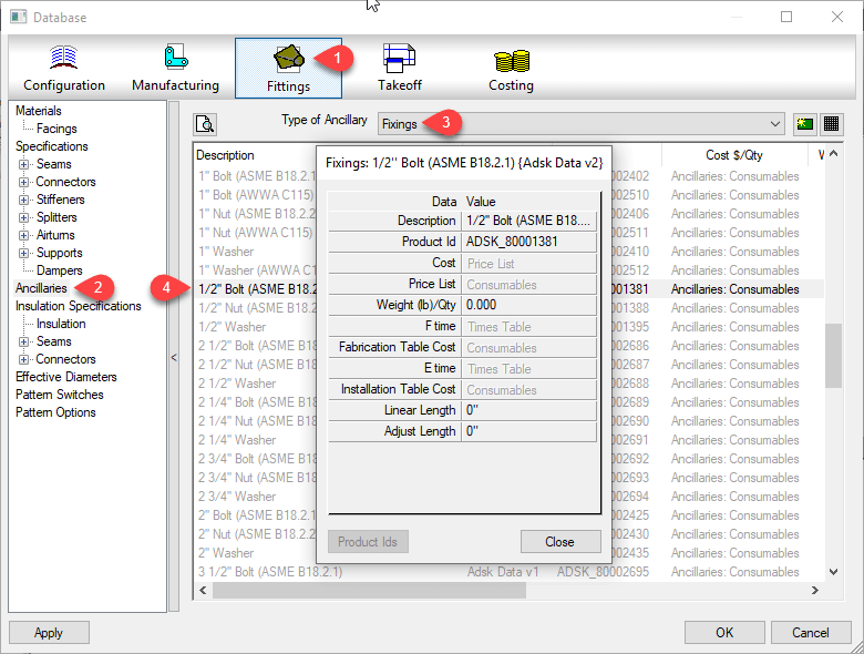
Ancillaries are virtual items you can add to your Fabrication configuration. ESTmep users use Ancillaries to help quantify cost and labor. Material quantification for purchasing and/or fabrication is another use for Ancillaries. These are virtual items because they typically don’t affect modeling or coordination. They aren’t even typically drawn yet they are critical to your fabrication as a purchased, fabricated or installed item.
Database view of an Ancillary entry
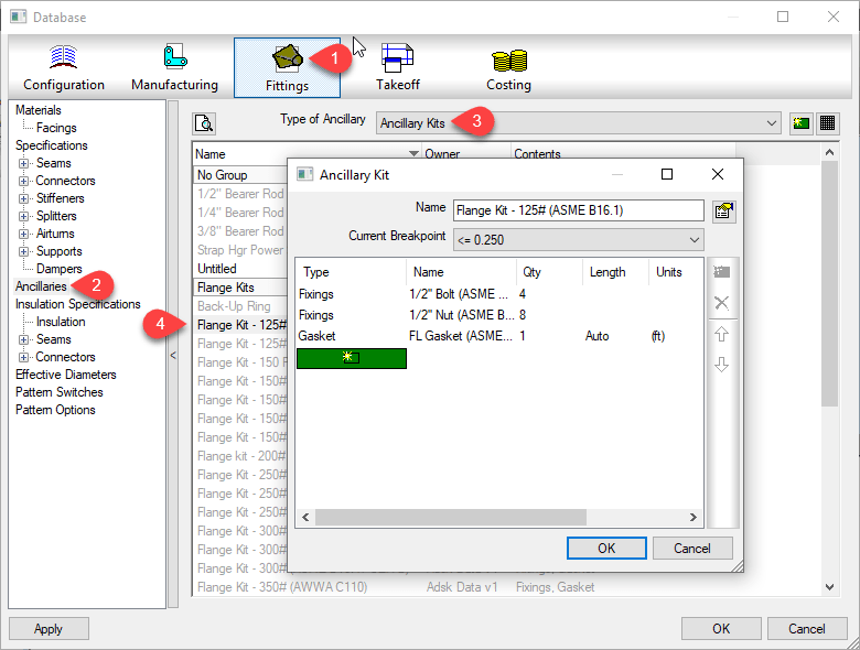
At times, you many need multiple Ancillaries associated with an item. However the fabrication software typically only allows you to assign a single ancillary to an item or database entry like a connector. For this reason, Autodesk Fabrication includes a type of entry called an “Ancillary Kit” in which you place multiple Ancillaries.
These Ancillary Kits are where you can group multiple Ancillaries that are often used together. A Bolt, Nut and Washers are a good example of an Ancillary Kit.
Database view of an Ancillary Kit entry
Ancillary / Kit Breakpoints
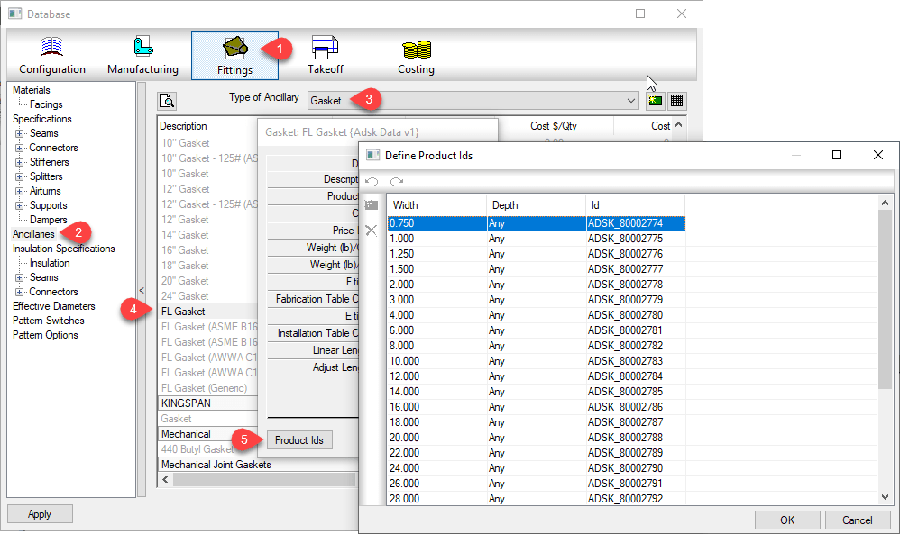
Often, Ancillary items are defined by the size of the item they are associated with. As an example, a flange gasket would be different depending on the type and size of flange it’s used with. You can configure an Ancillary to have Breakpoints to reference a different parts depending on the size of the item the Ancillary is associated with.
Database view of an Ancillary with Breakpoints
Just like Ancillariess, an Ancillary Kit can also have Breakpoints. Using a flange as our example again, depending on the type and size of a flange, or what it’s connecting to (another flange, valve, pump) it can have different bolt/nut sizes and quantities. You would manage this using an Ancillary Kit with Breakpoints.
Database view of an Ancillary Kit with Breakpoints
Nested Breakpoints
If you watched the example images closely, you can see Autodesk’s own database breaks this Best Practice rule. The rule is to never add Ancillaries that use Breakpoints to an Ancillary Kit. Here’s how to keep that straight…
Yes – Ancillary in Ancillary Kit
No – Ancillary w/Breakpoints in Ancillary Kit
Yes – Ancillary in Ancillary Kit with breakpoints
No – Ancillary w/Breakpoints in Ancillary Kit w/Breakpoints
I’ve not tested Autodesk’s configuration for reporting accuracy. I have enough work managing my own fabrication configuration. However I did create a sample of my own and submitted to Autodesk support. After demonstrating inconsistent results with my sample, their recommended guidance was not to use Ancillaries with Breakpoints in an Ancillary Kit.
Based on testing in other data sets, I would say this is sound advice. Even if you can get it to work, the setup and configuration is less intuitive and confusing. Your Ancillary Kit can reference different Ancillary types using different Breakpoint criteria. The Ancillary Kit could also have conflicting Breakpoint criteria (e.g. Length x Width vs Diameter) compared to the Ancillary.
Keeping this Best Practice can create more Ancillary entries as well as make building Ancillary Kits a little more time consuming. But the results will be more predictable and what’s really happening in your configuration will be more obvious and less obscure. Even where Breakpointed Ancillaries do function within an Ancillary Kit, it’s advised to avoid this where possible.
If you use network licenses or create network deployments of CADmep, CAMduct or ESTmep you may encounter errors. Autodesk incorrectly pathed the Network License Manager files in the SETUP.INI files.
Even if you are using Stand Alone or User Based Subscription licenses but build Network Deployments, if you configure the deployment to include all components in the deployment (recommended if you plan on modifying the deployment later) you can encounter errors.
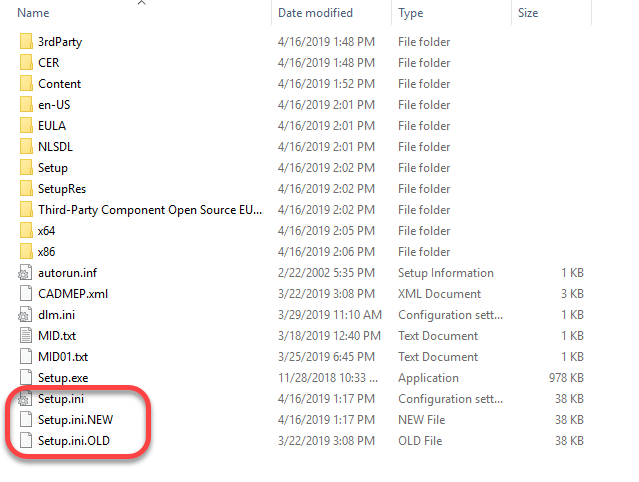
To correct the errors, you can replace the SETUP.INI files that are part of the installation with the ones provided in the following ZIP file…
Before you overwrite your installation’s SETUP.INI file, it’s a good idea to backup the original. The root of my installation folder looks like this…
At some point, I would expect Autodesk will update their download data and provide the proper files. Because of this, I would highly recommend NOT replacing the SETUP.INI files unless you encounter issues.
What’s Different?
If you’re curious what’s different between the two, you can open the INI files in Notepad or other text editor and view them there.
The original file contains this at the end of one of the entries…
Third-Party Component Open Source EULAs:x64\en-US\Tools\NLM.msi
The new SETUP.INI files have updated it to this…
Third-Party Component Open Source EULAs:x86\AdskLicensing\NLM\x64\NLM.msi
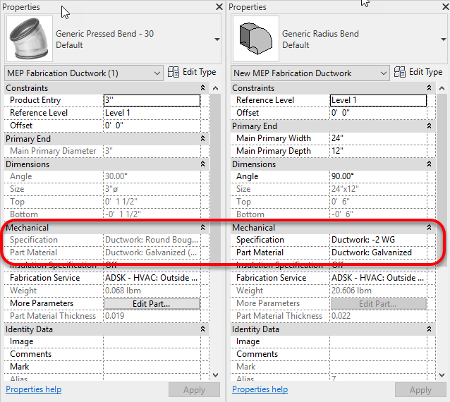
Fabrication Parts in Revit don’t always allow editing of their Material or Specification properties. Look at the below side by side images. Revit’s properties can be seen grayed out on the left but those on the right are not.
Material & Specification Properties – Left Read Only, Right = Read/Write
Revit can obscure the reason for this because you have no access to edit your Fabrication Database within the Revit environment. The answer however is quite simple.
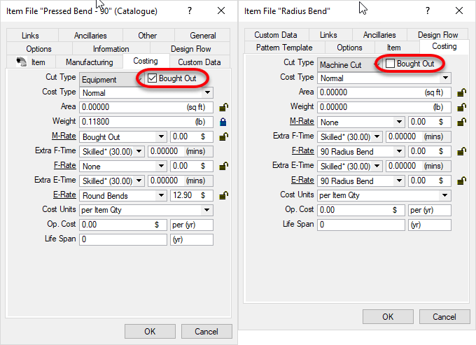
Fabrication Parts with the “BoughtOut” property set do not allow editing of Material or Specification. After all, a bought item is typically static and can’t be easily changed. Non-BoughtOut items do allow editing of the Material and Specification properties.
The following is another side by side image of Fabrication Part properties. The properties on the left have the BoughtOut property set. The properties on the right do not have the BoughtOut flag set. While not accessible from Revit, any of the other Autodesk Fabrication products can display and edit the BoughtOut property.
The following is an overview of the changes made to the AutoCAD 2020 release.
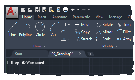
New Dark Theme
Improvements to the clarity and crispness of the dark theme. Similar sharpening was also applied to the light theme as well.
Background colors were optimized the with the icon colors to provide the optimum contrast without distracting from the workspace, where the focus should be.
Ribbon Access
Application button > Options > Display tab > Window Elements > Color Scheme
New Commands
None.
New System Variables
None.
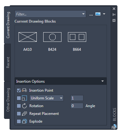
Blocks Palette
Redesigning the Insert dialog box was to provide better visual previews of blocks in the workflow for inserting blocks. The palette increases efficiency for finding and inserting multiple blocks-including the new Repeat Placement option, which can save you a step in some cases.
Key features in the new blocks palette facilitate your specifying and inserting blocks efficiently from a most recently used list or from specified drawings. Three tabs are available to provide the following:
The Current Drawing tab displays all the block definitions in the current drawing either as icons or as a list.
The Recent Blocks tab displays all the most recently inserted blocks either as icons or a list regardless of the current drawing. These persist between drawings and sessions. You can remove a block from this tab by right clicking it and choosing Remove from Recent List.
The Other Drawing tab provides a way of navigating to folders from which you can choose drawings either to insert as blocks or to choose from the blocks defined in those drawings. These drawings and blocks also persist between drawings and sessions.
The top of the palette includes several controls, including a field for applying wildcard filters to the block names, and several options for different thumbnail sizes and list styles.
Ribbon Access
Home tab > Block panel > Insert.
Access from the ribbon provides a gallery of the blocks available in the current drawing together with two new options, Recent Blocks and Blocks from other Drawings.
These two options open the Blocks palette either to the Recent tab or the Other Drawing tab. The gallery displays the same content as the Current Drawing tab.
Placing blocks from the palette can be accomplished by dragging and dropping or clicking and placing.
New and Changed Commands
BLOCKSPALETTE – Opens the Blocks palette.
BLOCKSPALETTECLOSE – Closes the Blocks Palette.
CLASSICINSERT – Opens the classic Insert dialog box.
INSERT – Starts the BLOCKSPALETTE command except in scripts, which open the legacy INSERT command for script compatibility.
-INSERT – Starts the command line version of the classic INSERT command.
New System Variables
BLOCKMRULIST – Controls the number of blocks displayed in the Recent tab of the Blocks palette.
BLOCKNAVIGATE – Controls the file and blocks that are displayed in the Other Drawing tab of the Blocks palette. Valid values include: Path/filename and extension to an existing file, and “.” (None), in which case the last-used file is remembered the next time the palette is opened and persisted across sessions.
BLOCKREDEFINEMODE – Controls whether the “Block- Redefine Block” task dialog box is displayed when inserting a block from the Blocks palette with the same name as a block inside the current drawing. 0= Don’t prompt to redefine-always use the local block definition. 1= Display the “Block – Redefine Block” warning dialog box when appropriate (Default).
BLOCKSTATE (Read only) – Reports whether the Blocks palette is open or closed.
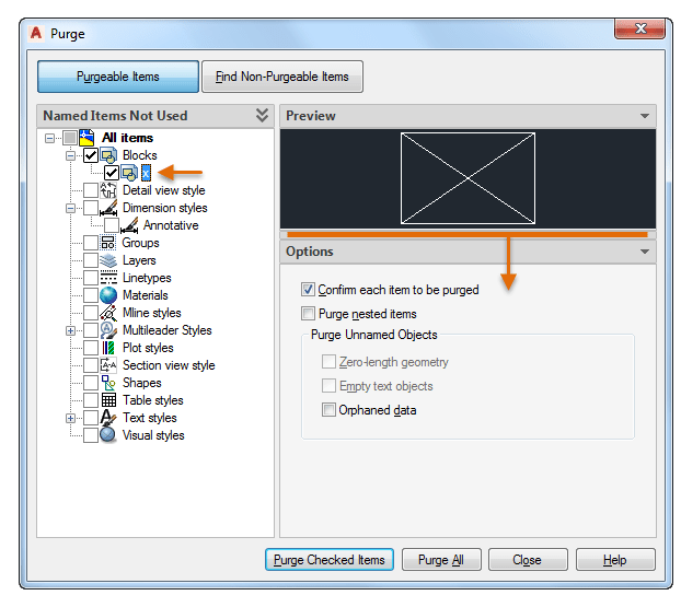
Purge Redesign
The Purge feature has been revised for easier drawing cleanup and organization. The control options are nearly the same, but the orientation is more efficient and a resizable preview area is now available.
You can now purge zero-length geometry without purging empty text objects.
Check boxes in the Named Items Not Used panel provide a way to select purgeable items by category as well as individual items.
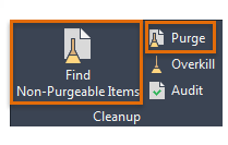
With one click, the Find Non-Purgeable Items button displays additional information specific to why the checked item cannot be purged, which will be helpful in many cases.
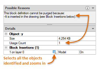
For objects that can’t be purged, the new design provides enhanced information as shown below, including the number of objects on which layers, and their impact on file size. The Select Objects button in the illustration below, zooms in on the specified objects that can’t be purged.
These options control whether Purgeable Items or Find Non-Purgeable Items is currently displayed in the Purge dialog box.
New Commands
None.
New System Variables
None.
DWG Compare Enhancements
The primary enhancement to the DWG Compare feature is that you can now directly compare and edit the current drawing together with a specified drawing while in the compare state. The changes you make in the current drawing are closely tied to the compared drawing and changes between the drawings are dynamically compared and highlighted.
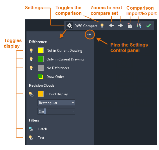
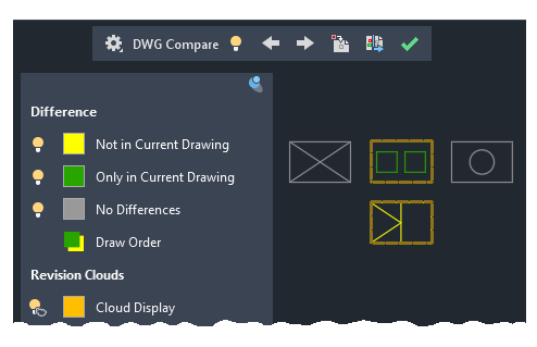
To facilitate direct editing in the compare state, the COMPARE command was moved from the ribbon to a docked toolbar at the top of the drawing area. Most of the options were combined into the Settings control and enhanced as shown. You can easily toggle the comparison from the toolbar and the display of the types of differences from the Settings control.
Also, the default colors can easily be changed by clicking on a color, red to yellow in this illustration, for your preferences or for colorblind-friendly colors.
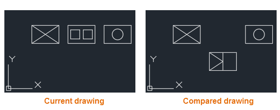
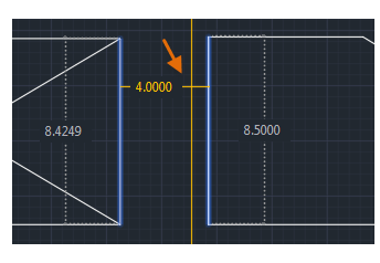
For example, let’s say you need to compare the differences between two highly complex drawings that have been simplified to look like the following:
The result of comparing the current drawing with the compared drawing looks like this:
The change sets are each surrounded by orange revision clouds, which are more clearly visible when you’re zoomed in.
You can import the highlighted differences (yellow) from the compared drawing into the current drawing. If you do so, these objects will now exist in both drawings and will automatically turn gray. Only the objects in the specified area that are not in the current drawing can be imported.
You can also export both drawings into a new “snapshot drawing” that combines the similarities and changes between both drawings. The result of this operation is the same as a drawing comparison in AutoCAD 2019.
The arrow buttons provide a way to step through each change set, automatically zooming in to each successive or previous change set.
Ribbon Access
Collaborate tab > Compare panel > DWG Compare.
New Commands
COMPARECLOSE – Closes the Compare toolbar and exits the comparison.
COMPAREEXPORT – Exports the comparison results into a new drawing, called a snapshot drawing, and opens the drawing.
COMPAREIMPORT – Imports objects from the compared file into the current drawing. Only the selected objects that exist in the compared file and not in the current file are imported.
New System Variables
None.
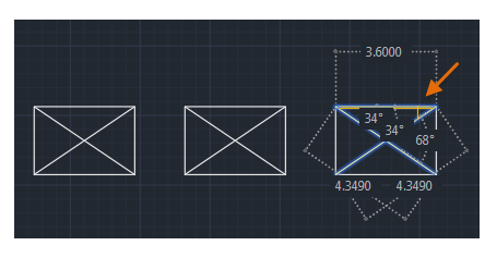
Measure Geometry Option-Quick Measure
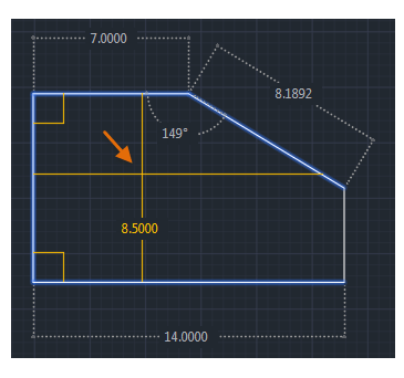
Measuring has become much faster with the new Quick option of the MEASUREGEOM command. With this option, you can quickly review the dimensions, distances, and angles within a 2D drawing.
When this option is active, the cursor displays all nearby measurements, both inside and outside the nearest parts of a drawing. The squares displayed at the left side of the illustration represent 90 degree angles.
The distance between the two objects is measured in the illustration below because they’re parallel.
Tip: To avoid quick dimension clutter and to improve performance, it’s best to zoom into complicated areas.
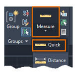
Ribbon Access
Home tab > Utilities panel > Measure/Quick.
Changed Commands
MEASUREGEOM – Adds the Quick option for real-time measurements.
New System Variables
None.
Save to Web & Mobile Enhancements
AutoCAD 2020 includes additional support for AutoCAD Web and AutoCAD Mobile. The enhancements are as follows:
Support cloud connectivity and storage. Depending on what you have installed, the Places list in AutoCAD file selection dialog boxes can include Box, Dropbox, and several similar services.
Xrefs are now included with the drawing files that you save for web and mobile access.
The CAD Manager Control Utility includes a new checkbox on the Online Content tab to disable the SAVETOWEBMOBILE and OPENWEBMOBILE commands. This control has been added for sites that require their drawings to remain within their organization’s network.
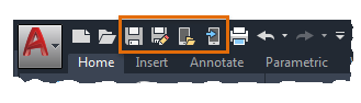
Access
Quick Access toolbar save and open commands:
New Commands
None.
New System Variables
None.
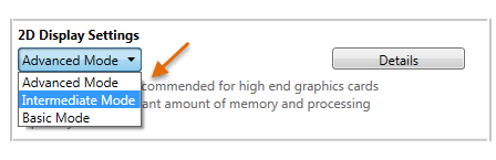
Graphics Configuration
AutoCAD now launches correctly with different DirectX drivers (Dx9, Dx11, or no driver), high resolution (4K) monitors, and dual monitors. In addition, the graphics display settings are consolidated into three modes, which includes gradient hatches and images. The graphics performance setting, Intermediate Mode, is updated to reset several display parameters automatically to optimize your display.
Access
Enter GRAPHICSCONFIG at the Command prompt.
The Graphics Performance dialog box displays, shown in part below.
Use the Same Version of software to Admin your Database
Consistently use the same version of software for all administration work. You can draw/model/estimate/etc using any version. Just make sure your users don’t have administrative permissions on their login. But for administering your database, always use the same version. Here’s why…
You can work in multiple versions of CADmep, ESTmep, CAMduct and even Revit (w/Fabrication Parts) using the same database configuration. In other words, the configuration itself is “Version Agnostic“.
For Revit Fabrication Parts, database compatibility starts with version 2016. The other Fabrication products like CADmep, ESTmep and CAMduct, compatibility goes back to at least the version prior to 2013, before Autodesk acquired the software.
What’s the problem?
You often get new functionality in newer versions of software. Versions of the software that require new data, automatically adds the new data to the database tables. When you only Use older versions of the software without administrative permissions, it ignores that extra data when it encounters it. This is why old versions work with configurations edited with newer versions,
When you try to use an older version to Administer your database, it rewrites those tables but doesn’t see the added data so it gets overwritten. This is why you should stick to the same version when editing your database.
You do not have to use the latest version to maintain your database. You can continue to use an older version for administration. Just don’t use a newer version then go back to the old. You’re perfectly fine to stick with an older version. You just won’t be able to take advantage of new features that rely on added data the new version offers. When you are ready to start using a newer version for Administration, you can make that change anytime but you should also stop using the older versions for administration.
Let’s Demonstrate the Issue
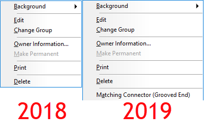
You can watch the video at the end of this article to see an example. In 2019 Autodesk added a new Connector setting for “Connector Matching”. We won’t go into what this does here but you can see in the following image the difference in the right-click menu of connectors.
Fabrication 2019 Added ‘Connector Matching‘
When you watch the video, you’ll see me switch between 2 different versions of ESTmep. I could use any product but ESTmep lets me quickly open and close a database so I can move between versions quickly.
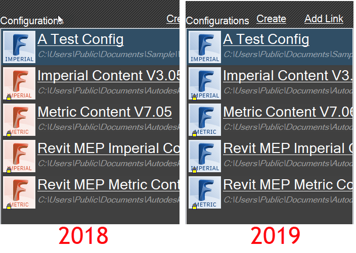
If you look at the configuration icons, you can see which version of software is being used. ESTmep 2019 has all BLUE icons. You can see ESTmep 2018 uses RED icons except the one BLUE 2019 configuration.
ESTmep 2018 has RED Configuration Icons, 2019 uses BLUE Icons
The video starts with “A Test Config” loaded in ESTmep 2019. I select one of the Connectors and change its ‘Connector Matching‘ value. Next, I exit and go back into the same configuration again in 2019 to show the value remains the same. At this point, everything is working as planned.
After exiting the database in 2019, I then switch to ESTmep 2018 and load the same “A Test Config” database. I make a copy of a completely different connector. This is where the problem starts. ESTmep 2018 has no knowledge of this ‘Connector Matching‘ data. Your “Connector Matching” data is over written as soon as ESTmep writes the Connector tables using the format it knows.
Finally, I go back into ESTmep 2019 and verify the data is gone. The default value for the Grooved Coupling’s “Connector Matching” data changes back to “Same“.
When you host a BIM360 Design project, adding members to the project is a common task. If you haven’t done this before, you may notice after typing the address thatBIM360 Design doesn’t seem to recognize it.
When you watch the video, you can notice the blue “Select” button grayed out after typing the Email address. You can type a ‘comma’ (,) after the address to make BIM360 recognize it. You’ll see the Email address converts to a boxed control when you type a properly formatted address.
When you type a comma, this tells BIM360 Design that you’re done typing the address. You can also use a comma to separate multiple addresses. This is why the comma works even when typing a single address.