SPOOL.INI Explained
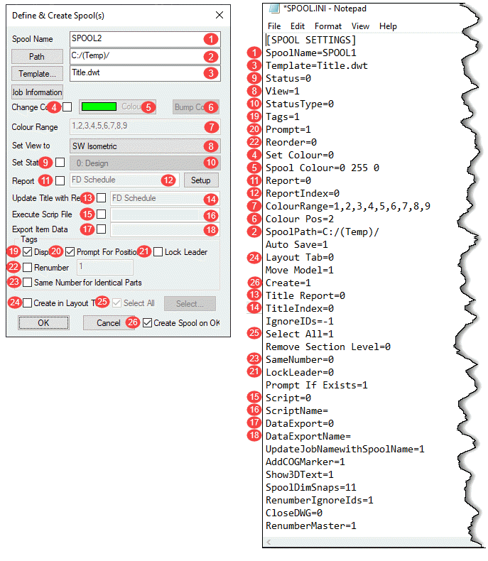
Most (but not all) of the settings in SPOOL.INI relate to the SPOOLDWG command dialog. The following image maps those fields in the dialog with those found in the SPOOL.INI file.
Values and description are listed in the below table along with some additional notes as well as settings related to spooling but not part of the SPOOLDWG dialog.
| Ref. | Setting | Value | Description | Note |
|---|---|---|---|---|
| 1 | SpoolName | Alpha/Numeric | Name of Spool | |
| 3 | Template | Path/Template Name | Name or Path & Name of AutoCAD Template for Spool Drawing. | |
| 9 | Status | 0 = Unchecked 1 = Checked | Set Status toggle in Spool Dialog. | |
| 8 | View | 0 = Plan 1 = SW Isometric 2 = SE Isometric 3 = NE Isometric 4 = NW Isometric 5 = None | Sets Spool drawing view type/orientation. | |
| 10 | StatusType | Status Index Number | Index Number of the Status as defined in your database. | |
| 19 | Tags | 0 = Unchecked 1 = Checked | Set Display toggle in the Spool Dialog. | |
| 20 | Prompt | 0 = Unchecked 1 = Checked | Set Prompt for Position toggle in the Spool Dialog. | |
| 22 | Reorder | 0 = Unchecked 1 = Checked | Set Renumber toggle in the Spool Dialog. | |
| 4 | Set Colour | 0 = Unchecked 1 = Checked | Set Change Colour toggle in the Spool Dialog. | |
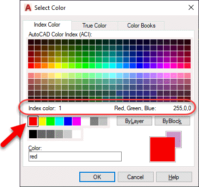
| 5 | Spool Colour | RGB Value | RGB (Red Green Blue) color value of the last spool. RGB Values are expressed as 3 integers, each between 0 and 255. Use AutoCAD DDCOLOR command to determine color numbers & corresponding RGB values. | Note 1 |
| 11 | Report | 0 = Unchecked 1 = Checked | Set Report toggle in the Spool Dialog. | |
| 12 | ReportIndex | Integer | Zero based index as listed in the drop down list in the Spool Dialog. e.g. 0 = 1st Report, 1 = second report, etc. | |
| 7 | ColourRange | Comma separated Integer List | List of Integers separated by commas. Represent the AutoCAD Color Index numbers (ACI) of the colors to cycle through for spool colors. Use AutoCAD DDCOLOR command to determine color numbers. | Note 1 |
| 6 | Colour Pos | Integer | Zero based index of color range for the last color used on a spool. | |
| 2 | SpoolPath | File Path | Folder where created spool drawings are located. | |
| n/a | Auto Save | 0 = No 1 = Yes | If Spooling to separate DWG's instead of Layouts should spool drawings should be saved after they are created. | |
| 24 | Layout Tab | 0 = Unchecked 1 = Checked | Set Create in Layout Tab toggle in the Spool Dialog. | |
| n/a | Move Model | 0 = No 1 = Yes | Sets if the spool be moved to 0,0,0 when creating the spool DWG's. | |
| 26 | Create | 0 = Unchecked 1 = Checked | Set Create Spool on OK toggle in the Spool Dialog. | |
| 13 | Title Report | 0 = Unchecked 1 = Checked | Set Update Title with Report toggle in the Spool Dialog. | |
| 14 | TitleIndex | Integer | Zero based index as listed in the drop down list in the Spool Dialog. e.g. 0 = 1st Report, 1 = second report, etc. | |
| n/a | IgnoreIDs | Comma separated Integer List | List of Integers separated by commas. Integers represent the Service Type Index. Items with these Service Type Indices will not be renumbered or have their item number displayed in the Spool. (Exception: See RenumberIgnoreIds setting) | Note 2 |
| 25 | Select All | 0 = Unchecked 1 = Checked | Set Select All toggle in the Spool Dialog. | |
| n/a | Remove Section Level | 0 = No 1 = Yes | Controls moving the Spool to 0,0 (X,Y) if 1/Yes or 0,0,0 (X,Y,Z) if 0/No when the Move Modelsetting is set set to 1. | |
| 23 | SameNumber | 0 = Unchecked 1 = Checked | Set Same Number for Identical Parts toggle in the Spool Dialog. | |
| 21 | LockLeader | 0 = Unchecked 1 = Checked | Set Lock Leader toggle in the Spool Dialog. | |
| n/a | Prompt If Exists | 0 = No 1 = Yes | Prompts to overwrite existing Spool DWG if it already exists. | |
| 15 | Script | 0 = Unchecked 1 = Checked | Set Execute Script File toggle in the Spool Dialog. | |
| 16 | ScriptName | COD Script File Name | Name of COD Script File to execute on the spool. Script name should be the file name only and NOT include the ".COD" extension. Script file must exist in the folder specified by SCRIPTS section of MAP.INI. | Note 3 |
| 17 | DataExport | 0 = Unchecked 1 = Checked | Set Export Item Data toggle in the Spool Dialog. | |
| 18 | DataExportName | IEX Report File Name | Name of IEX Data Export Report to run on the spool. Report name should be the file name only and NOT include the ".IEX" extension. Reports must exist in the proper product specific sub-folder under the reports folder specified by REPORTS section of MAP.INI. | Note 4 |
| n/a | UpdateJobNamewithSpoolName | 0 = No 1 = Yes | Updates the MAJ Job Name (Job Info) with the spool name prior to running any exports or reports. | |
| n/a | AddCOGMarker | 0 = No 1 = Yes | Calculates the Center of Gravity (COG) and inserts the COG Block (with attribute(s)) for the spool. | |
| n/a | Show3DText | 0 = No 1 = Yes | If showing annotations and the view is a 3d view, ensures that the database option is enabled to display in 3d. | Note 5 |
| n/a | SpoolDimSnaps | Integer | Enumeration (Bitwise) value for which OBject Snap Modes are set when using the SPOOLDWG command. | Note 6 |
| n/a | RenumberIgnoreIds | 0 = No 1 = Yes | Renumbers the list of Ignored parts specified in the IgnoreIDs setting and stores the setting in the Alias field. If the Alias already contains a value, the number will be appended to the value as a suffix. | |
| n/a | CloseDWG | 0 = No 1 = Yes | When spooling to separate DWG's instead of Layouts, will close the DWG after creation. | |
| n/a | RenumberMaster | 0 = No 1 = Yes | If renumbering, apply the new numbers to the Master DWG. |
Note 1:
The DDCOLOR Command in AutoCAD can be used to determine ACI (AutoCAD Color Index) and/or RGB (Red Green Blue) values.
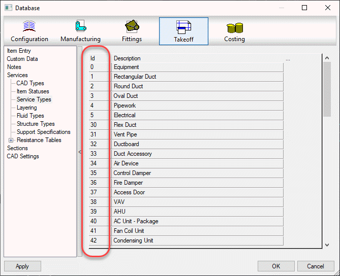
Note 2
Service Types can be found in the database editor. Use the Index Numbers in the Spool.ini settings.
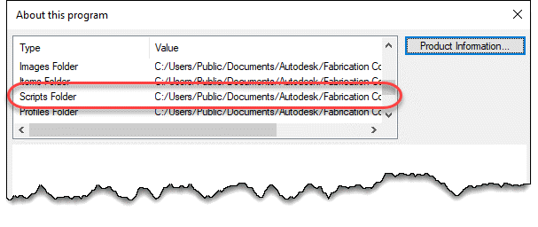
Note 3
COD Scripts must be located in the folder specified by the MAP.INI file.
Type the command APPINFO in CADmep to display a dialog which will show where the Scripts should be located.
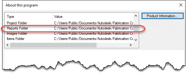
Note 4
IEX Data Export reports must be located in the software specific folder specified by the MAP.INI file. MAP.INI specifies the root folder for reports which are then found in a subfolder named based on the product using the reports. This makes knowing the exact reports folder a little difficult when looking in the MAP.INI file.
Tp more easily find the exact report folder, type the command APPINFO in CADmep to display a dialog which will show where the Scripts should be located.
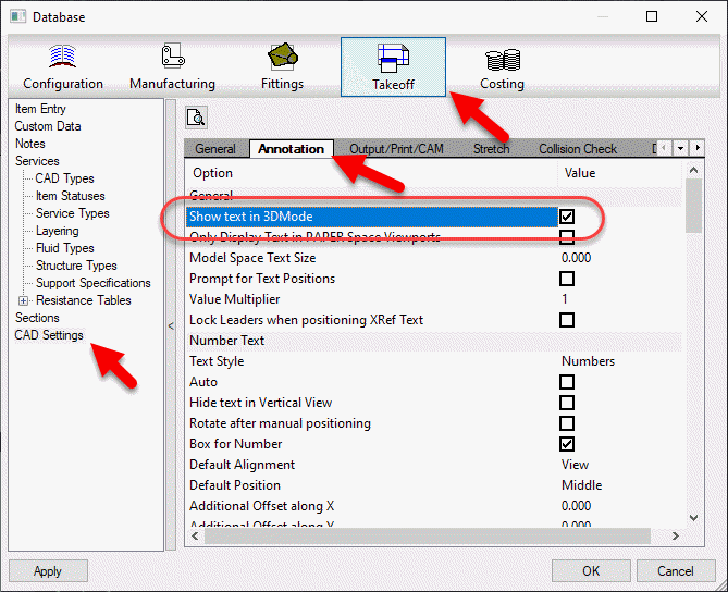
Note 5
The database setting this option controls can be found in the database editor under Takeoff -> CAD Settings -> Annotation.
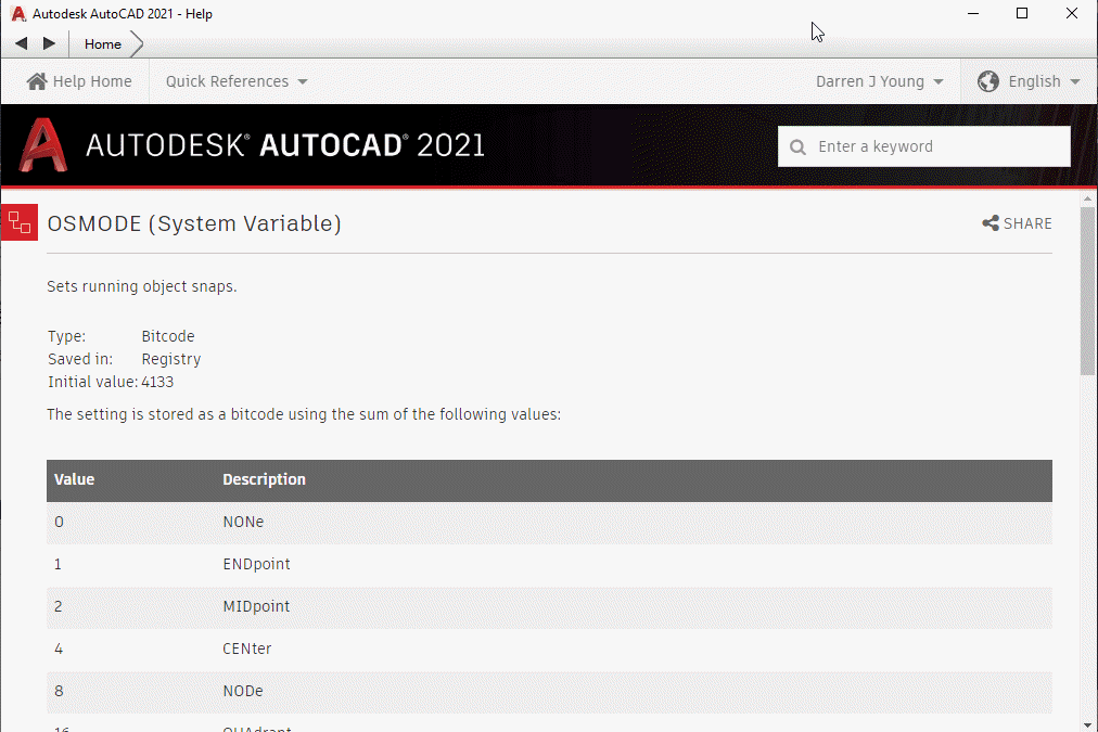
Note 6
To understand how bitcoded values work for the Snap modes, look up the OSMODE system variable in AutoCAD’s Help system.