Seems obvious once you see it but sometimes the easy things are the most ellusive.
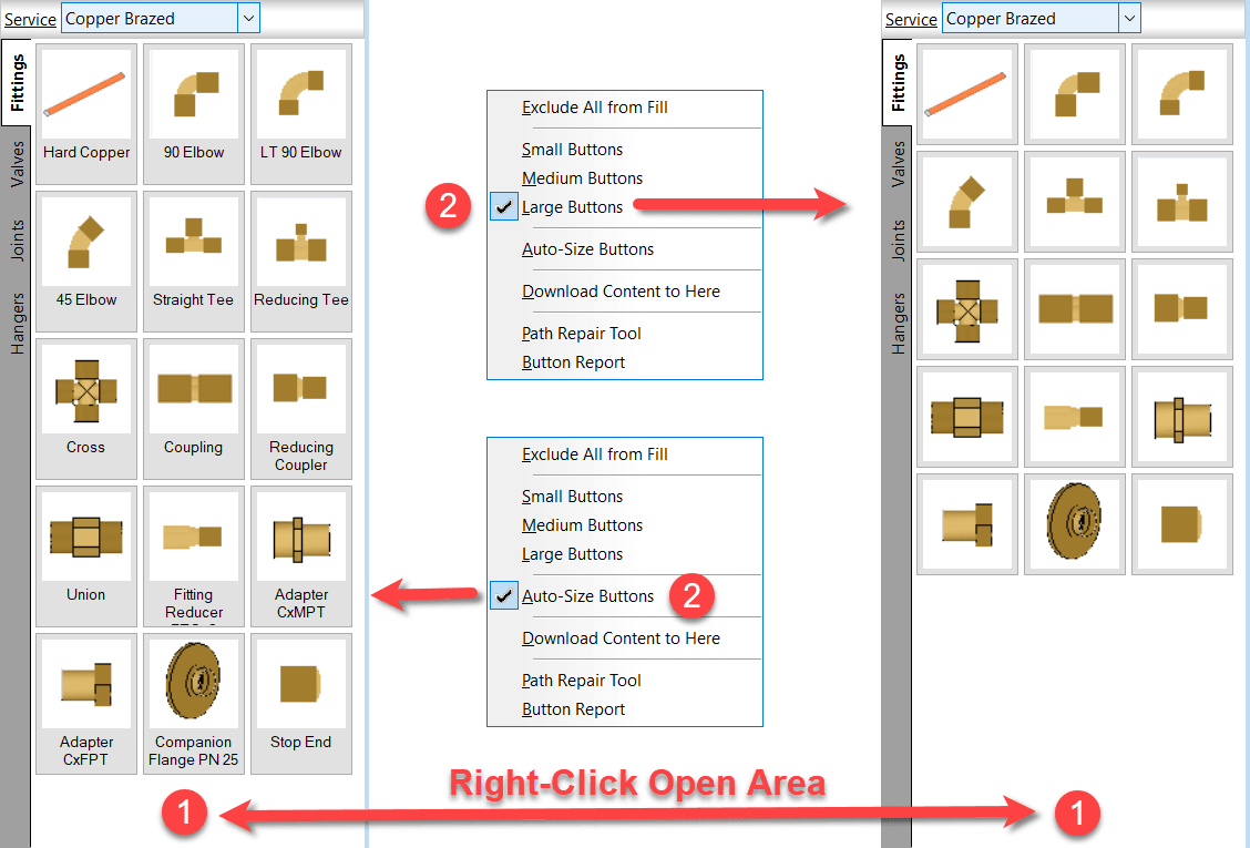
If you’re noticed descriptions on some of your computer’s fabrication palettes and not others, it’s likely the “AutoSize” option you’re looking for.
Right-Click on an open area of the service palette and select the option you prefer. This applies to CADmep, CAMduct and ESTmep. Revit…not so much. Revit likes to do it’s own thing.
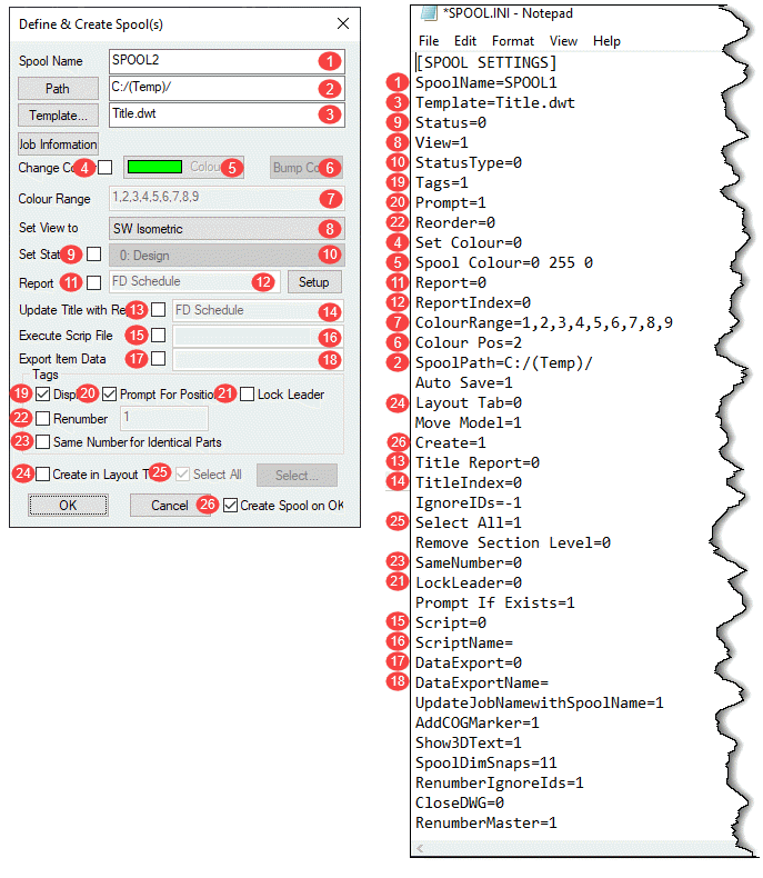
Most (but not all) of the settings in SPOOL.INI relate to the SPOOLDWG command dialog. The following image maps those fields in the dialog with those found in the SPOOL.INI file.
Values and description are listed in the below table along with some additional notes as well as settings related to spooling but not part of the SPOOLDWG dialog.
Ref.
Setting
Value
Description
Note
1
SpoolName
Alpha/Numeric
Name of Spool
3
Template
Path/Template Name
Name or Path & Name of AutoCAD Template for Spool Drawing.
9
Status
0 = Unchecked
1 = Checked
Set Status toggle in Spool Dialog.
8
View
0 = Plan
1 = SW Isometric
2 = SE Isometric
3 = NE Isometric
4 = NW Isometric
5 = None
Sets Spool drawing view type/orientation.
10
StatusType
Status Index Number
Index Number of the Status as defined in your database.
19
Tags
0 = Unchecked
1 = Checked
Set Display toggle in the Spool Dialog.
20
Prompt
0 = Unchecked
1 = Checked
Set Prompt for Position toggle in the Spool Dialog.
22
Reorder
0 = Unchecked
1 = Checked
Set Renumber toggle in the Spool Dialog.
4
Set Colour
0 = Unchecked
1 = Checked
Set Change Colour toggle in the Spool Dialog.
5
Spool Colour
RGB Value
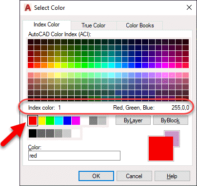
RGB (Red Green Blue) color value of the last spool.
RGB Values are expressed as 3 integers, each between 0 and 255.
Use AutoCAD DDCOLOR command to determine color numbers & corresponding RGB values.
Note 1
11
Report
0 = Unchecked
1 = Checked
Set Report toggle in the Spool Dialog.
12
ReportIndex
Integer
Zero based index as listed in the drop down list in the Spool Dialog.
e.g. 0 = 1st Report, 1 = second report, etc.
7
ColourRange
Comma separated Integer List
List of Integers separated by commas.
Represent the AutoCAD Color Index numbers (ACI) of the colors to cycle through for spool colors.
Use AutoCAD DDCOLOR command to determine color numbers.
Note 1
6
Colour Pos
Integer
Zero based index of color range for the last color used on a spool.
2
SpoolPath
File Path
Folder where created spool drawings are located.
n/a
Auto Save
0 = No
1 = Yes
If Spooling to separate DWG's instead of Layouts should spool drawings should be saved after they are created.
24
Layout Tab
0 = Unchecked
1 = Checked
Set Create in Layout Tab toggle in the Spool Dialog.
n/a
Move Model
0 = No
1 = Yes
Sets if the spool be moved to 0,0,0 when creating the spool DWG's.
26
Create
0 = Unchecked
1 = Checked
Set Create Spool on OK toggle in the Spool Dialog.
13
Title Report
0 = Unchecked
1 = Checked
Set Update Title with Report toggle in the Spool Dialog.
14
TitleIndex
Integer
Zero based index as listed in the drop down list in the Spool Dialog.
e.g. 0 = 1st Report, 1 = second report, etc.
n/a
IgnoreIDs
Comma separated Integer List
List of Integers separated by commas. Integers represent the Service Type Index.
Items with these Service Type Indices will not be renumbered or have their item number displayed in the Spool. (Exception: See RenumberIgnoreIds setting)
Note 2
25
Select All
0 = Unchecked
1 = Checked
Set Select All toggle in the Spool Dialog.
n/a
Remove Section Level
0 = No
1 = Yes
Controls moving the Spool to 0,0 (X,Y) if 1/Yes or 0,0,0 (X,Y,Z) if 0/No when the Move Modelsetting is set set to 1.
23
SameNumber
0 = Unchecked
1 = Checked
Set Same Number for Identical Parts toggle in the Spool Dialog.
21
LockLeader
0 = Unchecked
1 = Checked
Set Lock Leader toggle in the Spool Dialog.
n/a
Prompt If Exists
0 = No
1 = Yes
Prompts to overwrite existing Spool DWG if it already exists.
15
Script
0 = Unchecked
1 = Checked
Set Execute Script File toggle in the Spool Dialog.
16
ScriptName
COD Script File Name
Name of COD Script File to execute on the spool.
Script name should be the file name only and NOT include the ".COD" extension.
Script file must exist in the folder specified by SCRIPTS section of MAP.INI.
Note 3
17
DataExport
0 = Unchecked
1 = Checked
Set Export Item Data toggle in the Spool Dialog.
18
DataExportName
IEX Report File Name
Name of IEX Data Export Report to run on the spool.
Report name should be the file name only and NOT include the ".IEX" extension.
Reports must exist in the proper product specific sub-folder under the reports folder specified by REPORTS section of MAP.INI.
Note 4
n/a
UpdateJobNamewithSpoolName
0 = No
1 = Yes
Updates the MAJ Job Name (Job Info) with the spool name prior to running any exports or reports.
n/a
AddCOGMarker
0 = No
1 = Yes
Calculates the Center of Gravity (COG) and inserts the COG Block (with attribute(s)) for the spool.
n/a
Show3DText
0 = No
1 = Yes
If showing annotations and the view is a 3d view, ensures that the database option is enabled to display in 3d.
Note 5
n/a
SpoolDimSnaps
Integer
Enumeration (Bitwise) value for which OBject Snap Modes are set when using the SPOOLDWG command.
Note 6
n/a
RenumberIgnoreIds
0 = No
1 = Yes
Renumbers the list of Ignored parts specified in the IgnoreIDs setting and stores the setting in the Alias field.
If the Alias already contains a value, the number will be appended to the value as a suffix.
n/a
CloseDWG
0 = No
1 = Yes
When spooling to separate DWG's instead of Layouts, will close the DWG after creation.
n/a
RenumberMaster
0 = No
1 = Yes
If renumbering, apply the new numbers to the Master DWG.
Note 1:
The DDCOLOR Command in AutoCAD can be used to determine ACI (AutoCAD Color Index) and/or RGB (Red Green Blue) values.
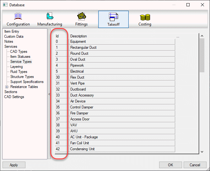
Note 2
Service Types can be found in the database editor. Use the Index Numbers in the Spool.ini settings.
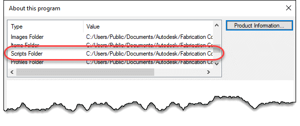
Note 3
COD Scripts must be located in the folder specified by the MAP.INI file.
Type the command APPINFO in CADmep to display a dialog which will show where the Scripts should be located.
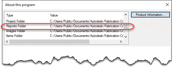
Note 4
IEX Data Export reports must be located in the software specific folder specified by the MAP.INI file. MAP.INI specifies the root folder for reports which are then found in a subfolder named based on the product using the reports. This makes knowing the exact reports folder a little difficult when looking in the MAP.INI file.
Tp more easily find the exact report folder, type the command APPINFO in CADmep to display a dialog which will show where the Scripts should be located.
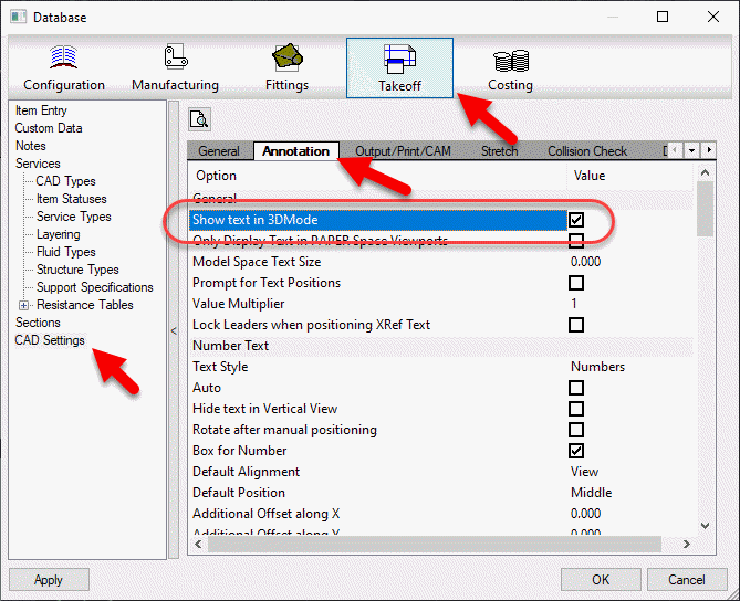
Note 5
The database setting this option controls can be found in the database editor under Takeoff -> CAD Settings -> Annotation.
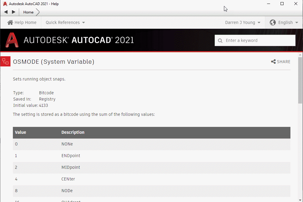
Note 6
To understand how bitcoded values work for the Snap modes, look up the OSMODE system variable in AutoCAD’s Help system.
CADmep, ESTmep and CAMduct all use the concept of an Attacher. This is what tells Fabrication which way to route elbows and branches.
Most people know how to place and rotate the Attacher. There are a few other tricks to working with the Attacher that you may not know about.
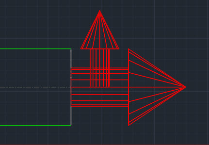
Up or Down, How to Get Around
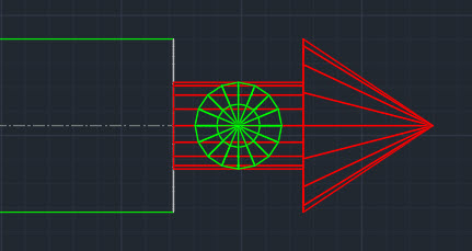
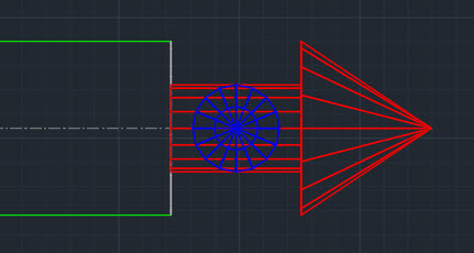
Depending on your view orientation, you may notice part of the Attacher turns from Red to Blue or Green. As you rotate the Attacher it’s color will change to indicate the direction the arrow is pointing.
Green = Grass (Attacher is pointing away from you)
Blue = Sky (Attacher is pointing toward you)
Rotation Tricks
Depending oh which program you’re in (CADmep, ESTmep or CAMduct) and the keys you press, the Attacher rotates differently. Here’s a chart explaining those nuances.
Rotation
Method
CADmep
ESTmep
CAMduct
90 Degrees CCW
Click
Yes
Yes
Yes
90 Degrees CW
Shift+Click
No
Yes
Yes
180 Degrees (Flip)
Ctrl+Click
Yes
Yes
Yes
15 Degrees CCW
Alt+Click
Yes
No
No
CADmep – Click Attacher to Rotate Counter Clockwise 90 DegreesCADmep – Ctrl+Click Attacher to Rotate 180 Degrees (Flip)CADmep – Alt+Click Attacher yo Rotate Counter Clockwise 15 DegreesESTmep / CAMduct – Click Attacher to Rotate Counter Clockwise 90 DegreesESTmep / CAMduct – Shift+Click Attacher to Rotate Clockwise 90 DegreesESTmep / CAMduct – Ctrl+Click to Rotate Attacher 180 Degrees (Flip)
If you use network licenses or create network deployments of CADmep, CAMduct or ESTmep you may encounter errors. Autodesk incorrectly pathed the Network License Manager files in the SETUP.INI files.
Even if you are using Stand Alone or User Based Subscription licenses but build Network Deployments, if you configure the deployment to include all components in the deployment (recommended if you plan on modifying the deployment later) you can encounter errors.
To correct the errors, you can replace the SETUP.INI files that are part of the installation with the ones provided in the following ZIP file…
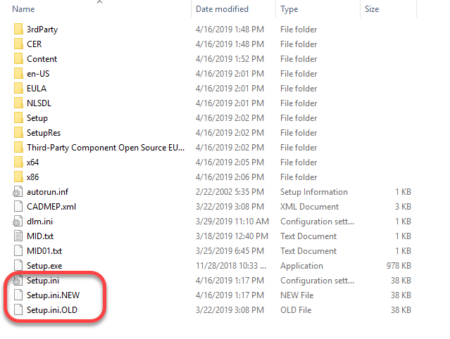
Before you overwrite your installation’s SETUP.INI file, it’s a good idea to backup the original. The root of my installation folder looks like this…
At some point, I would expect Autodesk will update their download data and provide the proper files. Because of this, I would highly recommend NOT replacing the SETUP.INI files unless you encounter issues.
What’s Different?
If you’re curious what’s different between the two, you can open the INI files in Notepad or other text editor and view them there.
The original file contains this at the end of one of the entries…
Third-Party Component Open Source EULAs:x64\en-US\Tools\NLM.msi
The new SETUP.INI files have updated it to this…
Third-Party Component Open Source EULAs:x86\AdskLicensing\NLM\x64\NLM.msi
Here’s another simple Attacher tip for Fabrication products. If you hold down the Shift key while clicking on the Attacher arrow in CADmep, ESTmep or CAMduct,. the arrow rotates the opposite direction.
Clickingthe Attacher – Notice it Rotates in the “Clockwise” Direction Clickingthe Attacher – Notice it Rotates in the “Counter-Clockwise” Direction
Sometimes the best tips are the simplest. They can often be forgotten about or never learned because of that. Here’s a reminder for those that may not know or have forgotten…
In CADmep, or the 3d viewer of ESTmep or CAMduct, you can hold the Control key while clicking the attacher arrow to rotate the arrow 180 degrees. The below screen recordings are both done from CAMduct but ESTmep or CADmep work just the same.
Clickingthe Attacher – Notice it Rotates in 90-Degree IncrementsCtrl-Clicking the Attacher – Notice it Rotates in 180-Degree Increments
Over the years, I’ve written a number of scripts helpful for managing an Autodesk Fabrication configuration. I’ve given them away in my Autodesk University session I’ve taught so they’ve circulated around a bit.
I’ve rewritten most, streamlined them, made enhancements, added others, etc, etc. Because I’m always updating and changing them, I thought I’d host them here too. I can then just post when I update them.
There’s are 2 sets of scripts covering the following topics…
Debugging Properties Scripts
Job Item Scripts
Library Item Scripts
One set is for use in 2019.0 and earlier versions (but work in any version), the others are designed for 2019.1 and later when Autodesk added support for the Pattern Number property.
You can get to the scripts from the menu or click here. The scripts are free to use for all except employees of ENGworks or anyone working on the behalf of ENGworks. (contractors, consultants, etc.) who are prohibited from use.
When you build content, it’s often desirable to have certain dimensions or options locked. This even applies to connectors, seams and dampers but to a lesser degree.
If you have a lot of Dimensions and/or Options to Lock or Unlock, you don’t have to individually pick each one. You can lock or unlock many very quickly provided they’re in a row.
The trick is simple….pick the button to lock/unlock the first field you want to change, and then while still holding the pick button drag your mouse up or down. This is a fast an efficient way to lock large groups of properties without picking each one.
The following recording shows this process. We’re using Pattern Number (CID) 910 as our example.
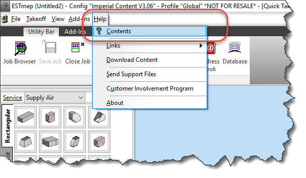
It’s sometimes easy to miss new things. This is why I want to point out something that was added in 2015. CADmep now has an APPHELP command. You can type APPHELP at the command prompt to bring up CADmep’s help system.
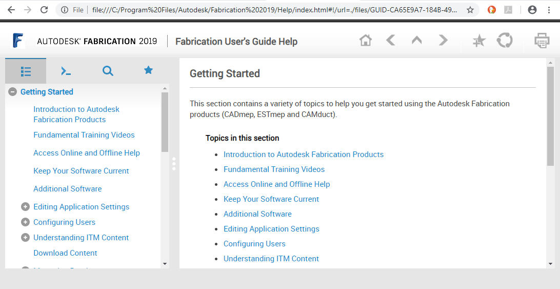
If you’re online, the help is pulled from Autodesk’s web site from the following URLs…
But what if you’re using CAMduct or ESTmep? No worries. The other products work the same way. Instead of typing APPHELP, type F1 on your keyboard or use the Help pull down menu.
Only One Concurrent Database Administrator at a Time.
If you use a shared database (such as on a network location), you’ll want to lock down who can edit the database and restrict that to a single concurrent user. Many areas of the Autodesk Fabrication database are large tables. If two or more users have the ability to edit those tables at the same time, you’re asking for problems. That is, the last user to edit the database wins and the other looses their changes.
Here’s how that happens….
User A logs in with full administrative permissions. User B then logs in with full administrative permissions.
At this point, both users are on the same page because they both loaded the database into the computer’s memory.
Now lets say, User A creates some new materials and connectors for some content they are building. At the same time, User B creates a new service and exits.
User B now has their new service written to the database on the server. That’s good. But User A doesn’t have those changes, they opened the database before those changes were made. When User A exits the database, what’s in memory on their computer gets written back. This is their new connectors and materials, but also the original list of Services without User B’s changes.
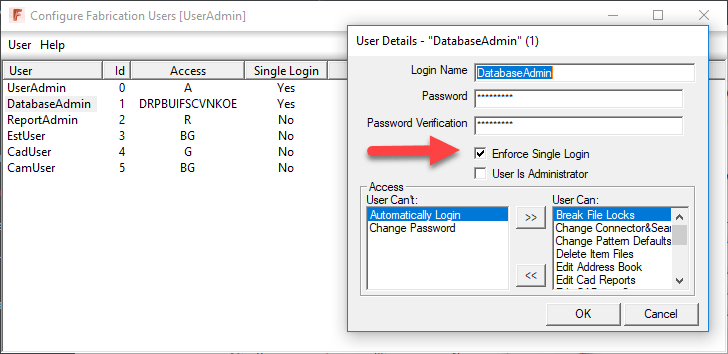
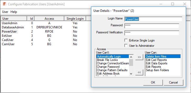
For this reason, it’s a good idea to create a separate user account used only for Database Administration work and limit it to a single concurrent user. To do this, use the “Configure Users” program that comes with all of the Fabrication products. The following image shows the setting that allows a single concurrent user and all the settings this account could (should) have.
Now if you look closely, you may notice I typically have a couple other Admin accounts in there. Once users are setup, you typically don’t need to mess with them again so I create a separate account only for this purpose but you wouldn’t have to, it could be combined with the “DatabaseAdmin” account.. This is the “UserAdmin” account shown in the image. I also restrict this to a single concurrent user and guard it’s password to only a few select people who really understand how the Fabrication Database works.
For every rule, there’s an exception and you’ll also see a “ReportAdmin” account. This account is NOT restricted to a single concurrent users and here’s why…
When you edit most database settings, you’re editing a large database table with lots of entries. When you edit a report, you’re editing a single file for that report only. The chances that two or more people will edit the same report at the same time is very small. This means multiple users can create multiple reports at the same time and each will save to their own file.
Much like Reports, content (ITM files) are separate file based and will most likely not have more than one person editing the same ITM at the same time. This means you could also create a separate “ContentAdmin” account that lets you setup and delete folders only (no other permissions). Alternatively, you could combine both of the Report and Content accounts into a single “PowerUser” account that does both like in the following image…
Using a less restricted account like this allows more people to create Reports or Content without creating a bottleneck in your workflow. Those creating ITM’s won’t be able to create new connectors or materials or other settings, but they can make new ITM’s that point to existing database entries. This will help you scale your content building activities when you get a last minute request for a large library of pipe fittings. Your primary database admin will use the restricted “DatabaseAdmin” account to create the needed materials and connectors, and you can then have a large number of users making ITM’s using the “PowerUser” account in a safe manner,
Based on a lot of years experience, I’ve been told many times by people that they are careful to not have two or more people go in at the same time and don’t need to restrict their accounts. But I can also tell you, the more I make sure it can’t happen with these restrictions instead of letting them assure me it doesn’t happen because they’re “careful”, the less “unexplained” problems and corruption I see.