You may have noticed a new setting in Fabrication 2025. You can see it when you edit the properties of a Service Template. It’s shows as Maximum # couplings. Valid settings are 1 to 10. So what is this setting you may ask? Well, don’t go with your instincts. The name is as unintuitive as possible.
To start, couplings are any ITM made from Pattern (CID) 2522. So not necessarily an actual “pipe” coupling. So this setting only applies to any fitting made from Pattern 2522 regardless of what it does in the real world. No other patterns are affected.
Your initial instinct might be that this limits the number of coupling patterns on a service template. You’d be wrong. When you think about it, a lot of things are made from Pattern 2522. Couplings obviously, but also Welds, Flanges. some Reducers, Adaptors, Unions, Bolt Sets, Gaskets, etc. That can easily push the number over 10. So what exactly does this do?
First, a little background. To start this setting only applies to Revit. No other Fabrication products are affected aside from using them to edit the setting. Next, you should know that there was always a coupling limit as it pertained to Revit. It was hard coded to 6 I’m told. This change in the 2025 Fabrication products made it editable to a smaller (minimum 1) or larger number (maximum 10).
What this settings does is control the connect and coupling logic in Revit. Revit’s autofill features like Route and Fill, Multi-Point Routing, Quick Connect and Design to Fabrication are affected. This is because the coupling pattern is special. In most scenarios, pipe is connected to fittings. In come cases, fittings to fittings. Coupling patterns on the other hand, can connect to other coupling patterns repeatedly.
These autofill functions need to process the various options for fittings. This can have performance implications that increase exponentially the more parts you have using those patterns. Let’s look at an example….
The below image shows a pipe flange connection. It’s using 6 coupling patterns in a row in the model. But in your service, there may be even more. Different types of flanges, welds, gasket and bolt set options, etc. It needs to look at all of those to determine the options available. In this case, a coupling limit of 6 would work. That’s how many 2522 patterns you would ever string together to make this connection. So after 6, Revit no longer needs to keep looking for couplings and can limit it’s analysis to other pipe or fittings in your service.
As you can see, the old hard coded value of 7 would be enough to cover most flanged or dielectric connection options. In some very limited edge cases, you might need more. So now you can bump it up to 10. However, you may want to actually reduce it lower. If you’re using ancillaries for gaskets and bolt sets and not drawing ITM’s to quantify them, a setting of 4 would be sufficient. For some systems, you might even be able to go lower.
What happens if the coupling limit is lower than what’s needed? Well, you might have to make those connections manually. Autofill functions wouldn’t provide all of the possible options. In some cases, you might event get broken connections.
Personally I’ve not been able to create a sample dataset and configuration that really demonstrates functionality working or not based on the setting. For the most part, it’s likely not going to affect most users however lowering it might provide some performance improvements in Revit. They tell me ideally the setting would be 3 or 4. But as you can see, if you’re using ITM parts for Bolt Sets and Gaskets, 6 is likely your “Go To” number. But on a plastic system? 3 or 4, maybe even 2 would be sufficient.
Do you know what ‘Connector Matching’ is as it relates to Autodesk Fabrication? It’s been in the product since the 2020 release. Yet most people I run into have no clue what it is.
There’s a good reason for that. It’s hidden from view. That is to say, there’s a good reason you don’ know about it. There’s no good reason it’s hidden from you besides Autodesk is pretty slopping (lazy?) when it comes to product design in recent years.
What is Connector Matching?
Connector Matching only works in Revit w/Fabrication Parts. If you’re not using Revit, you need not worry about it but setting it up won’t cause any issues either. It’s designed to place a matching connector on pipe after you cut in a fitting when modeling in Revit. CADmep, ESTmep and CAMduct will simply ignore the settings.
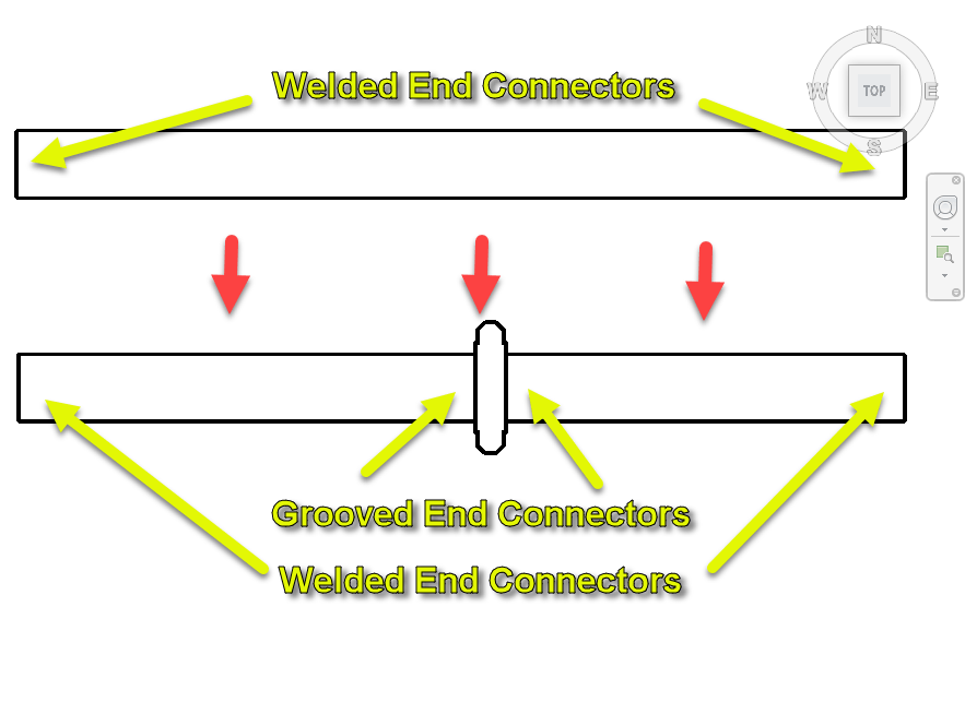
As an example, if you’re drawing a welded piping system and want to break it with a Grooved coupling, Connector Matching places the proper grooved connector on the end of the pipe when the Coupling is placed. This helps us build a system with Welded Pipe Spools that’s assembled in the field with Grooved Couplings…a very common activity in mechanical construction.
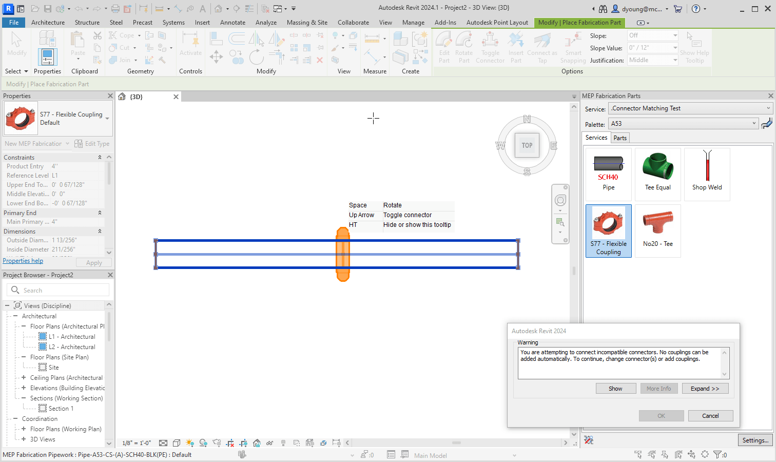
When Connector Matching isn’t configured, you’ll have issues cutting in things like a Grooved Coupling into a Pipe that’s part of a welded system.
Configuring Connector Matching
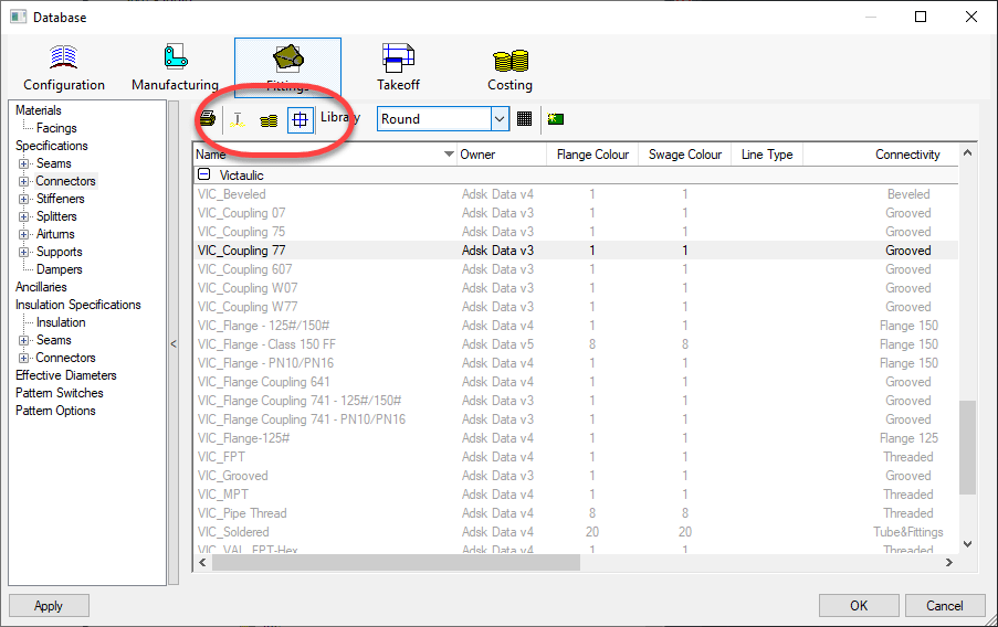
The reason many don’t know about connector matching is because it’s hidden. None of the 3 views (Manufacturing, Costing & Drawing) display this option.
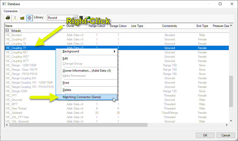
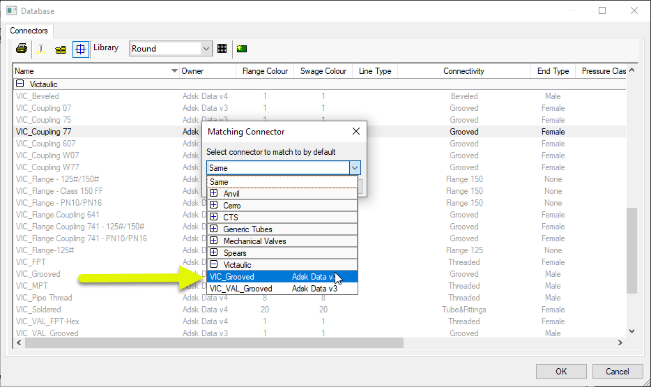
To set Connector Matching, you Right-Click on a connector that’s configured for the Item you need to match. In this case, it’s a Victaulic 77 Coupling.
You can see the Matching Connector is set to “Same” by default. That’s certainly not what we need so select that menu option.
You can see now the Matching Connector is set to a Grooved Connector. So every time an Item with the “VIC_Coupling 77” connector is cut into a piece of pipe, the pipe will get a “VIC_Groove” connector.
Added Configuration to Make it Work
Above, you set the matching connector. Unfortunately, that’s not enough. There’s some added configuration to verify to ensure that it works.
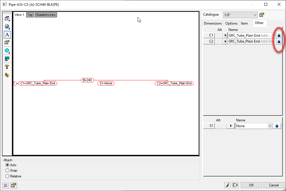
One of the requirements of Connector Matching is to make sure the Pipe’s Connectors are NOT locked and defaulted to the connectors they should use. In other words, ‘Set’ but not ‘Locked’.
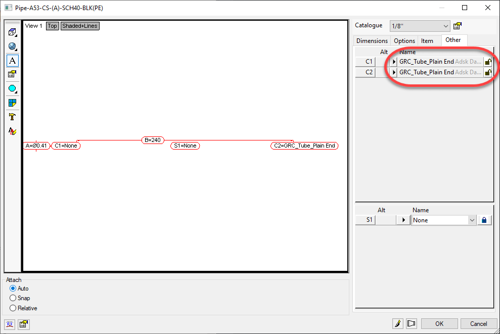
Here’s what your Pipe ITM most likely looks like…
What I recommend here is, Unlocking only 1 of the Connectors and Clicking OK. After you do that, go back and edit the ITM again and take a look at the Connectors.
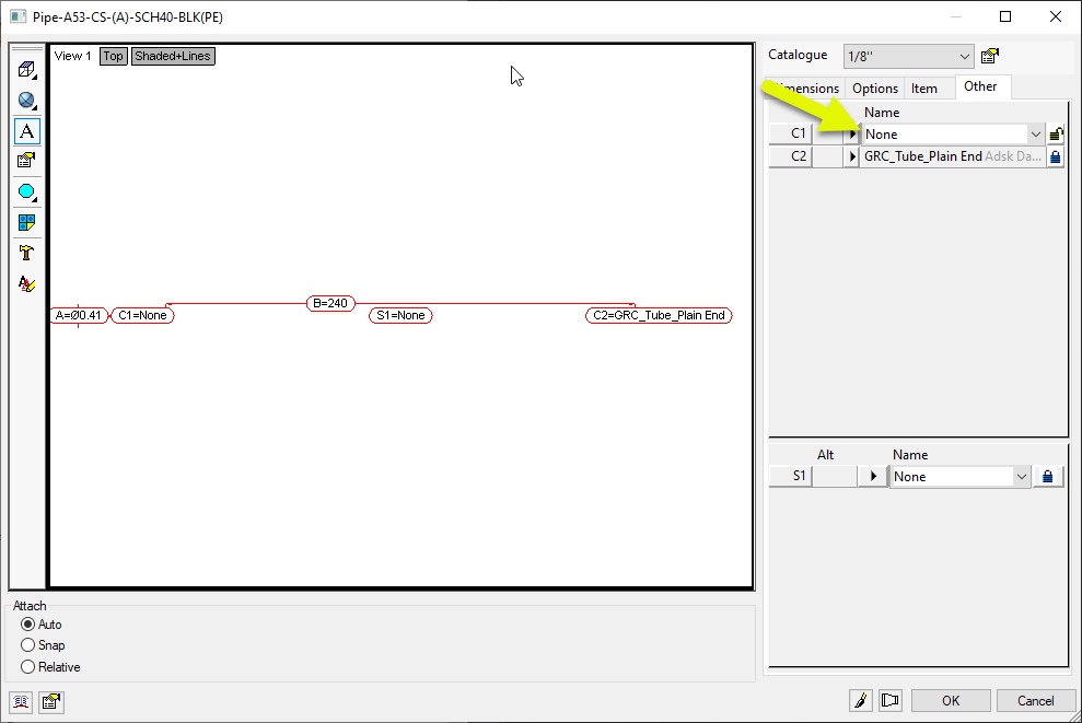
You can see here that after Unlocking one of the Connectors and Clicking OK, going back to edit the ITM the Connector changed to “None”. This is a tell tale sign that there’s yet another thing you have to change to make it work.
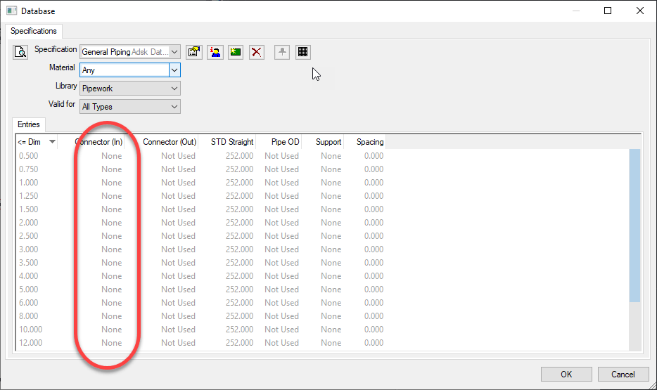
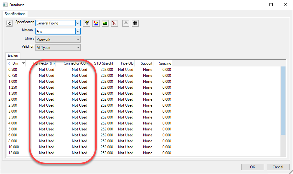
In some Configurations, people have the Specification set to drive the Connectors. This is most commonly done for Sheetmetal but you see it in Piping as well. In the following image, the Piping Specification is configured to set the Connector to “None”.
What we need to do here is set the Connectors in the Breakpoints to “Not Used”. Note, if the Connector you unlocked earlier didn’t change to something other that what it was, you most likely don’t have this issue but still could…it could just be configured to use the Connector the ITM was set to.
You might have to hunt around for which settings apply. It could be on the ‘Any’ material or a specific material the ITM is using. The ‘Valid For’ could have it in ‘All Types’ or ‘Straights Only’. It’s possible too that you don’t have any breakpoints in the Specification at all. If that’s the case, then your Specification is likely already good. But if it’s not, simply ensure the Connectors are all set to “Not Used”.
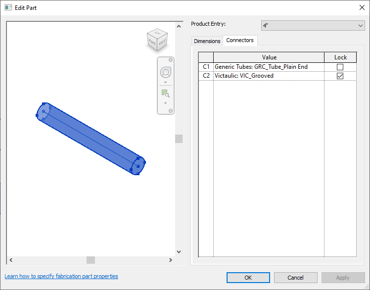
Once your Specification is setup correctly (if it was a problem in the first place) you can go back to your ITM for the pipe and unlock both connectors but leave them set to the Connector it typically uses.
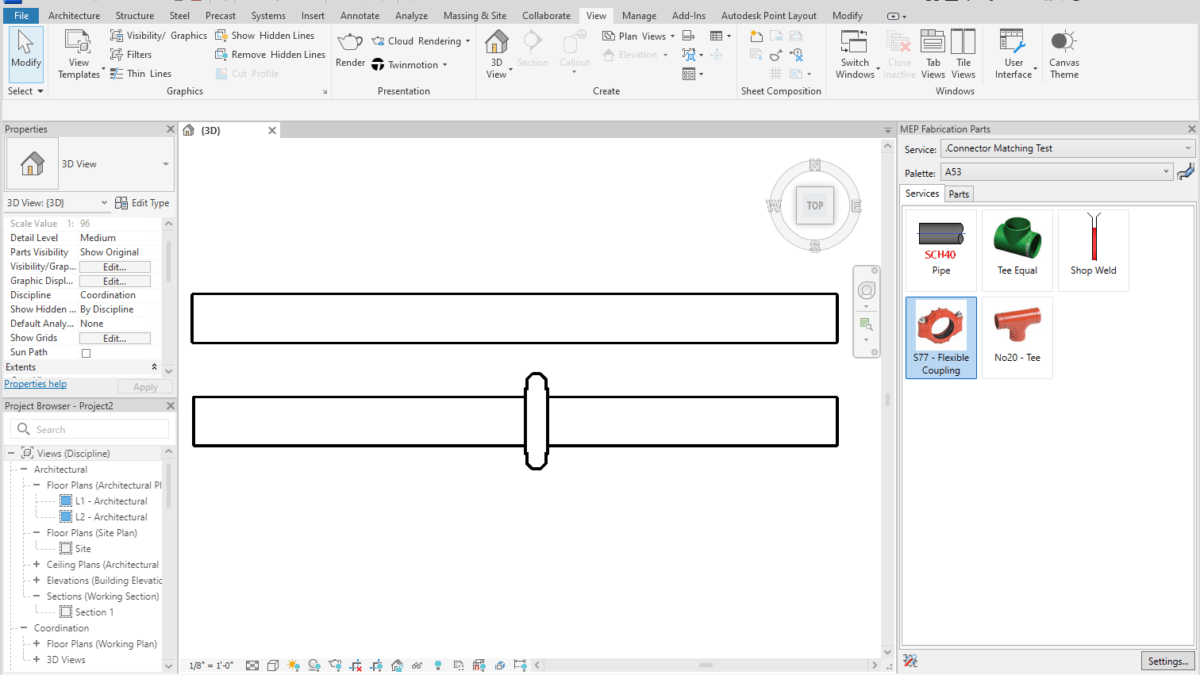
Once everything is set properly, Revit will then let your Grooved Coupling be placed in the run of pipe.
If you Double-Click on one of the pieces of pipe, you can see the Connectors are now set to a Groove for the end where the Coupling is.
A Final Word
Note that these settings were added in 2020. If you’ve had your Database configuration a long time, they’re likely not set. Even Autodesk’s ‘Out of the Box’ configurations that shipped with 2024 don’t have these set. So you’re pretty much on your own to make it work.
If you do ANY Administration of your Database Configuration in 2019 or earlier, these settings will be lost. As I’ve advised many times earlier, pick a version for Administration and stick to it. If you have Admin permissions and use 2019 or earlier, all those settings get lost and because they’re not displayed, you won’t really know.
You can use these settings for all kinds of things. They don’t have to be limited to Grooved Couplings. Changing the end of Steel pipe to Threaded when Cutting in a Threaded Coupling, Threaded Adaptor, Threated Tee, Threaded Valve, etc. All of these things should have their connectors looked at and Matching setup. Just about any of those types of fittings in all materials should have Matching set.
I run into a number of people who have had problems with Riser Clamps and Revit Fabrication Parts. I have as well. Here’s how you can work around them…fairly easily.
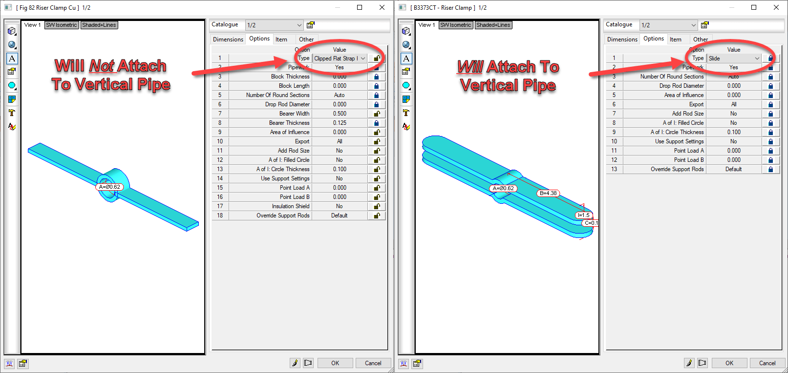
Problem #1 – Clamp Will Not Attach to Vertical Riser
The first problem I see is with Riser Clamps not attaching to vertical pipe. I’ve seen some creative workarounds. From just placing a clamp in space and moving it to near where it should be to using a modified form of a Grooved Coupling pattern. The following video shows what that would look like if you have this issue.
The fix for this issue is fairly simple. First, make sure you’re using Pattern Number (CID) 838. This is the original Hanger pattern that will allow you to make just about any hanger. Secondly, ensure that you select the ‘Slide‘ option on the pattern.
This is the ONLY Hanger option that will work for vertically oriented pipe.
Once you use the proper option, you can observe that a Riser Clamp will attach to the vertical pipe. This can be seen in the following video.
The second Riser Clamp’s configuration uses the ‘Slide’ option. This allows us to attach it to vertical pipe. This sets us up well for the next issue….oversizing.
Issue #2 – Oversized Riser Clamps
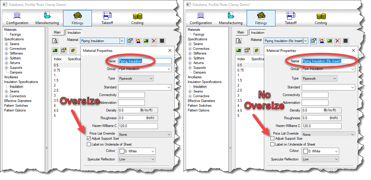
The second issue is that if you set your Insulation Specification’s material to Oversize Hangers, the Riser Clamp will also oversize. This isn’t something you do with a Riser Clamp. Many of us have brought this issue to Autodesk on several occasions, yet they seem to struggle with understanding of our need for an option in this pattern to “ignore” oversize.
Luckily, with a little added work and user intervention, we can work around this. To resolve the issue, create a secondary Riser Insulation Specification with a material that does not oversize hangers.
To do this, you’ll need a duplicate of your Insulation Material. In the image below, we configure the insulation on the right not to oversize for systems where we do not require thermal pipe inserts.
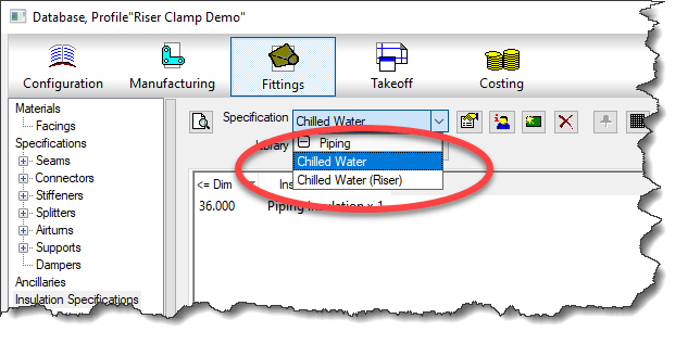
Once you have a secondary Insulation material, you can create the Insulation Specification for the Riser.
Now, all you need to do is override the Insulation Specification on the Riser (vertical pipe) before placing the Riser Clamp. You can see this in the following video.
You can see how the vertical pipe get’s a pipe sized Clamp, where as the horizontal pipe will still oversize because we didn’t change it’s insulation specification.
I’d like to thank Kevin Allen and William Tucker of Comfort Systems USA for pointing out this embarrassingly simple workaround for Insulation Specification that seemed to escaped me.
I’ve been seeing a recent trend in project teams. An increasing use of Autodesk Desktop Connector to link Revit Cloud Models. While it can and does work (sometimes), it’s a real bad idea and should be avoided unless absolutely needed. The reasons are subtle and nuanced. But those nuances are a make or break in terms of success.
I’ll try to explain as best I can. I’ll even give you steps you can do to reproduce this issue yourself. But first, let’s go over why Desktop Connector exists in the first place.
A Brief Desktop Connector History
Autodesk’s first attempt at a proper Cloud workflow for Revit was called Collaboration for Revit. It later became BIM360 Design and today is called BIM360 Collaborate Pro. Same idea…take a Revit model and manage it in the Cloud from Sync’d local data. Practically speaking, it’s a cloud version of Revit Server.
Back in those early days, you could link to other Revit cloud models. But Revit supports other types of links besides RVT files. So people would link to file servers. But in a collaborate environment, other teams didn’t have the same file servers or folder structures. Those other linked files linked DWG’s or IFC’s would break. So like the good technologist’s they are, BIM Managers started using services like Dropbox across the product team. Those non-Revit files were linked from there so the links would be common across of team members.
As a result, Autodesk later acknowledged the value in doing this and released it’s own ‘sync’d drive’ tool called Autodesk Desktop Connector. So that’s why it’s there. It’s intended to link non-Revit files or Revit files that are NOT cloud models.
One could argue that Autodesk should have just made Collaboration for Revit work with those other files types. I agree and it’s a nice thought. But it’s likely not the case because the Revit files you see on BIM360 Docs (now Autodesk Docs) are NOT the same files as are used by Revit’s Cloud collaboration tools. You can read more about that here (https://www.darrenjyoung.com/2022/03/29/the-2-sides-of-bim360-acc-docs/)
The False Alure of Desktop Connector
When I see Desktop Connector misused, the reason I’m given is usually the same. “We don’t want to Live Link models“. That’s to say, they don’t want to see daily changes from the other project teams in real time.
So that sounds reasonable. But if people would use BIM Collaborate Pro ‘properly’ this actually solves this problem and in a much more flexible way. BIM Collaborate Pro when setup and used properly allows 3 separate workflows or a combination of any of them….
Link to Live Models
Link to “Shared” copies of Models (only updates when the model owner chooses to share)
Link to “Consumed” copies of Models (only update when you consume a shared copy)
Yup. That’s it. Complete flexibility on how you link to other Revit Cloud Models. In short, if you’re linking to get away from updates you don’t control, it’s because you’re not using the BIM Collaborate Pro properly. More accurately, whoever is hosting the project did not set it up properly and you’re a mere casualty caught in the cross fire. Something most sub-contractors are very familiar with.
The True Appeal of Desktop Connector
There’s really another reason people use Desktop Connector for Revit Cloud models. A result of Autodesk’s flawed logic that everyone on the project should be on the same platform, same project and same account. While it makes sense at a high level, it also means all other project teams who aren’t the hosting company are limited to the willingness and/or capabilities of the hosting company.
Taking that into account, one aspect of Desktop Connector is that you can link ‘between’ BIM360 or ACC (Autodesk Construction Cloud) accounts. That is, you can link files in your account, to project files in another team’s account. This cross account linking is NOT available in BIM Collaborate Pro with Cloud models or Cloud Workshared models but it is in the Desktop Connector.
When you put this all together, this means companies can link to files from other companies but still control their own models on their own account. And they’re not live linked either. This is why we’re seeing a proliferation in Desktop Connector usage with Revit Cloud Models.
The new Autodesk Construction Cloud has some “Bridge” functionality designed to facilitate this. I tested the Bridge functionality when it first came out. It didn’t work as required, expected or as advertised IMO. It may or may not have improved since then but that’s not the point of this article. The point of this article is about linking to Revit Cloud models from Desktop Connector. Why it’s problematic, not a recommended best practice and why it should be avoided.
The Desktop Connector Problem
To demonstrate the problem, we’ll use two separate sets of 3 Revit files each linked to each other within the set like the following…
Set 1(problem set)
Test – 1.rvt(Link to Test – 2.rvt & Test – 3.rvt)
Test – 2.rvt(Link to Test – 1.rvt & Test – 3.rvt)
Test – 3.rvt(Link to Test – 1.rvt & Test – 2.rvt)
Set 2(working set)
Test – A.rvt(Link to Test – B.rvt & Test – C.rvt)
Test – B.rvt(Link to Test – A.rvt & Test – C.rvt)
Test – C.rvt(Link to Test – A.rvt & Test – B.rvt)
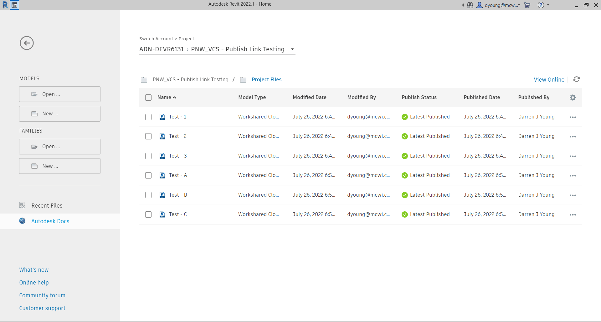
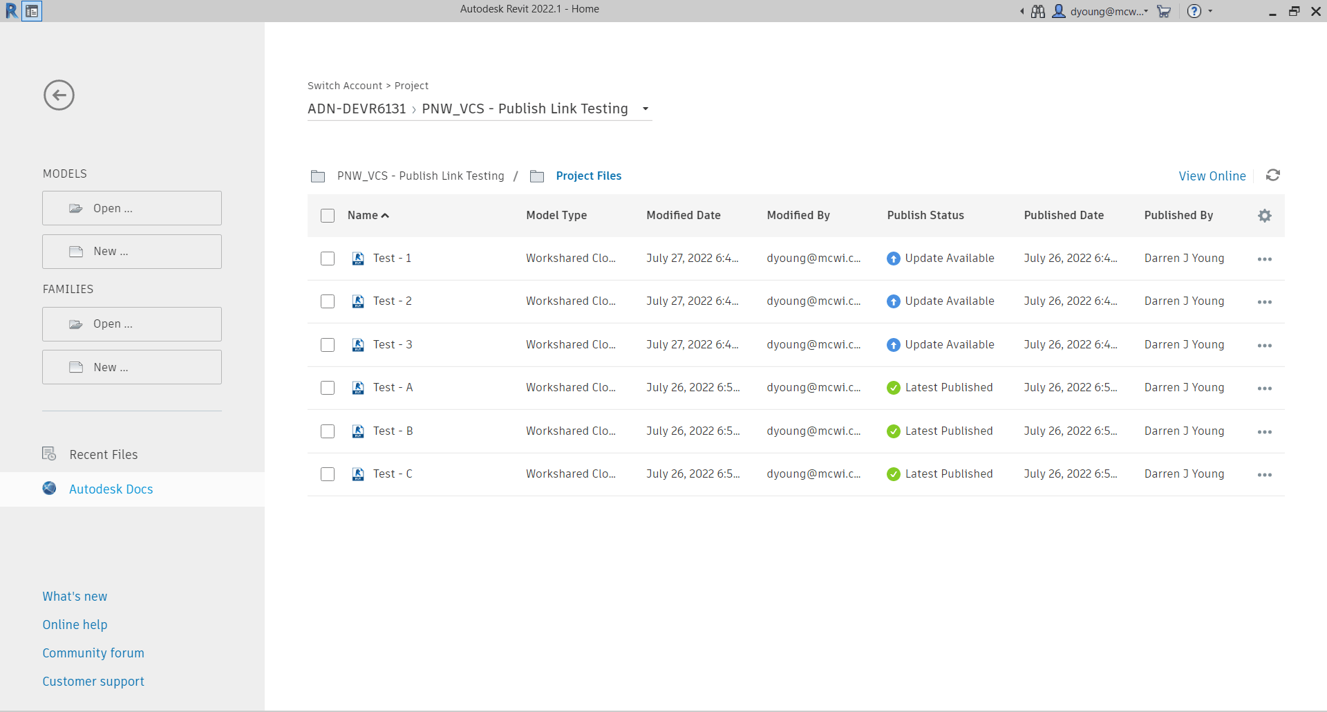
Each Revit model is a Cloud Workshared Model. (a standard Cloud Model would function the same for this issue). You can tell they’re Cloud Models be viewing them in Revit’s interface like shown in the following image…
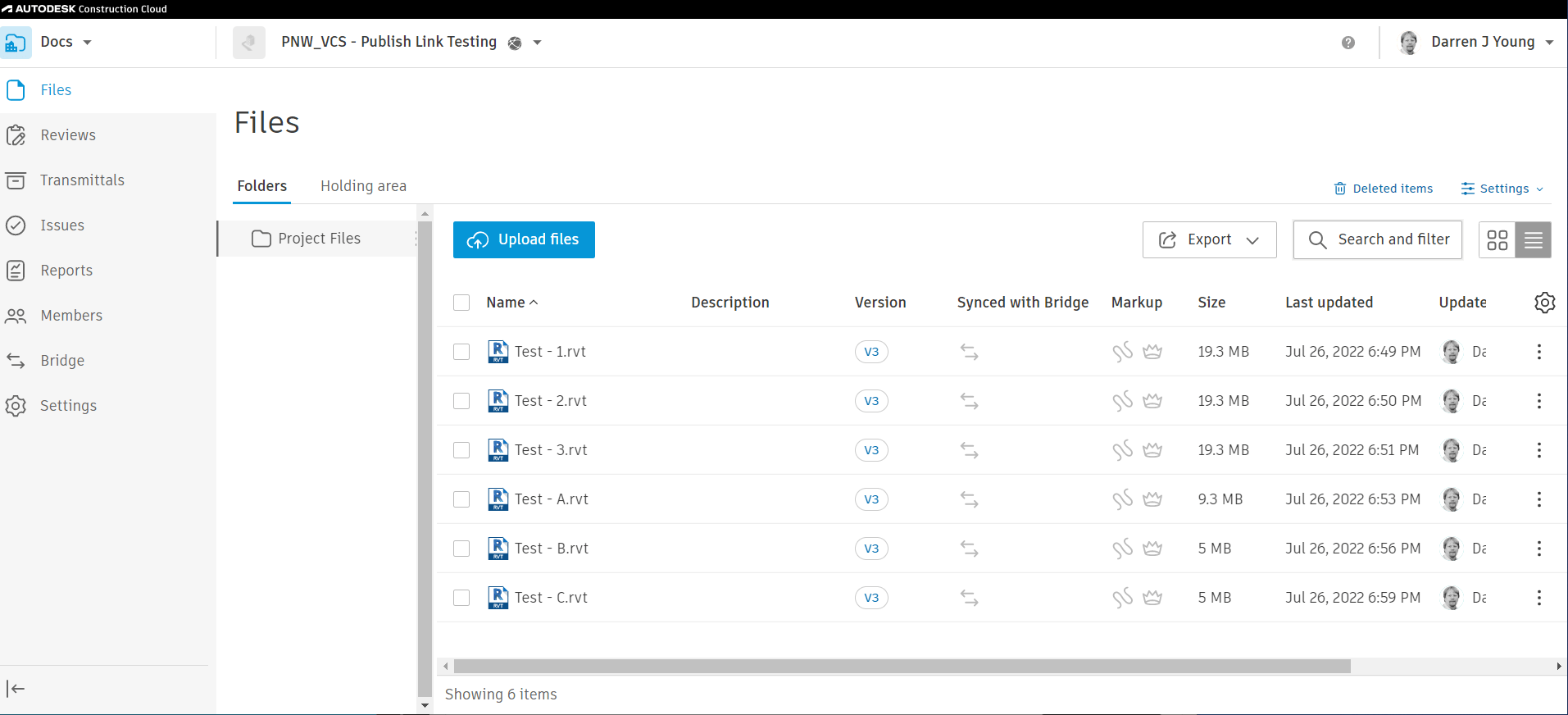
If any of the Revit files were not Cloud Models, they wouldn’t appear here in Revit but would appear from the BIM360 or ACC web interface. You can see in the following image, those same files are listed in the web interface. They were all published so the version in Autodesk Docs displays the same contents as is available in BIM Collaborate Pro.
So far, all seems fine. The files you see in the BIM360 or ACC interface are the same ones that are available in Desktop Connector. Now here’s where the issues starts to manifest itself.
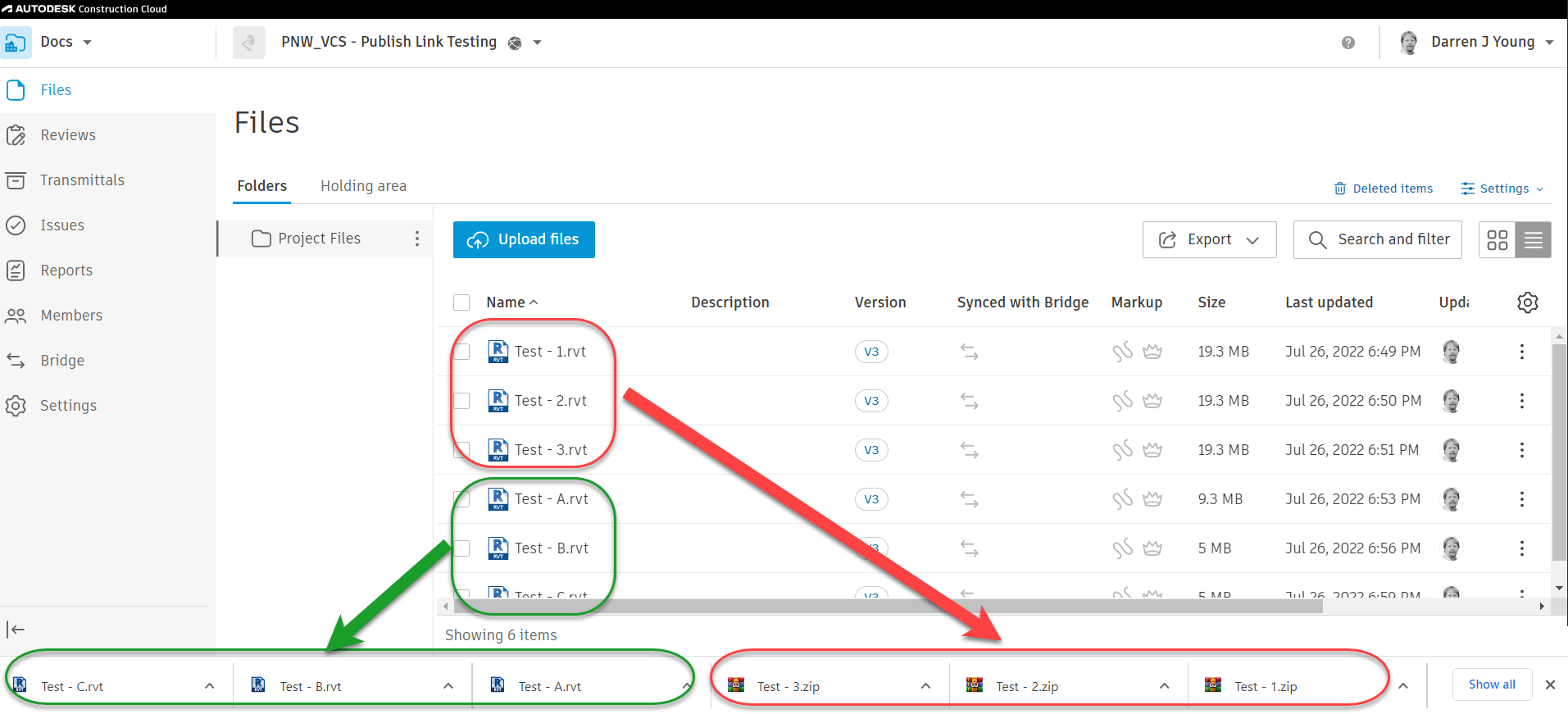
Take a look at what happens when we try to download the Revit Models from the web interface. Set 1, the numerical set download as ZIP files. Set 2 on the other hand, that alphabetic models download as Revit files.
Perhaps you’ve seen this before. I know many users who assume that the ZIP file downloads are there because the Revit files contain links. Because a non-linked model always downloads as an RVT. Other users think it’s part of the whole “Share/Consume” workflow of BIM Collaborate Pro. Both explanations are technically incorrect.
The following image shows the files and their downloaded names. Keep in mind that each set is a model collaborated in the Cloud the exact same way and linked the exact same way. In fact, they themselves are not linked from the Desktop Connector either. They’re linked properly through the “External Resources”. Aside from the files names, they are identical in every way.
Further Proof – RVT Doesn’t Mean RVT
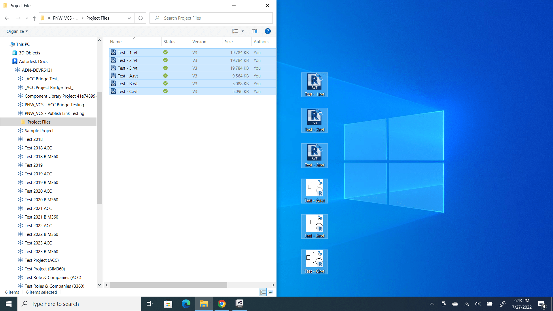
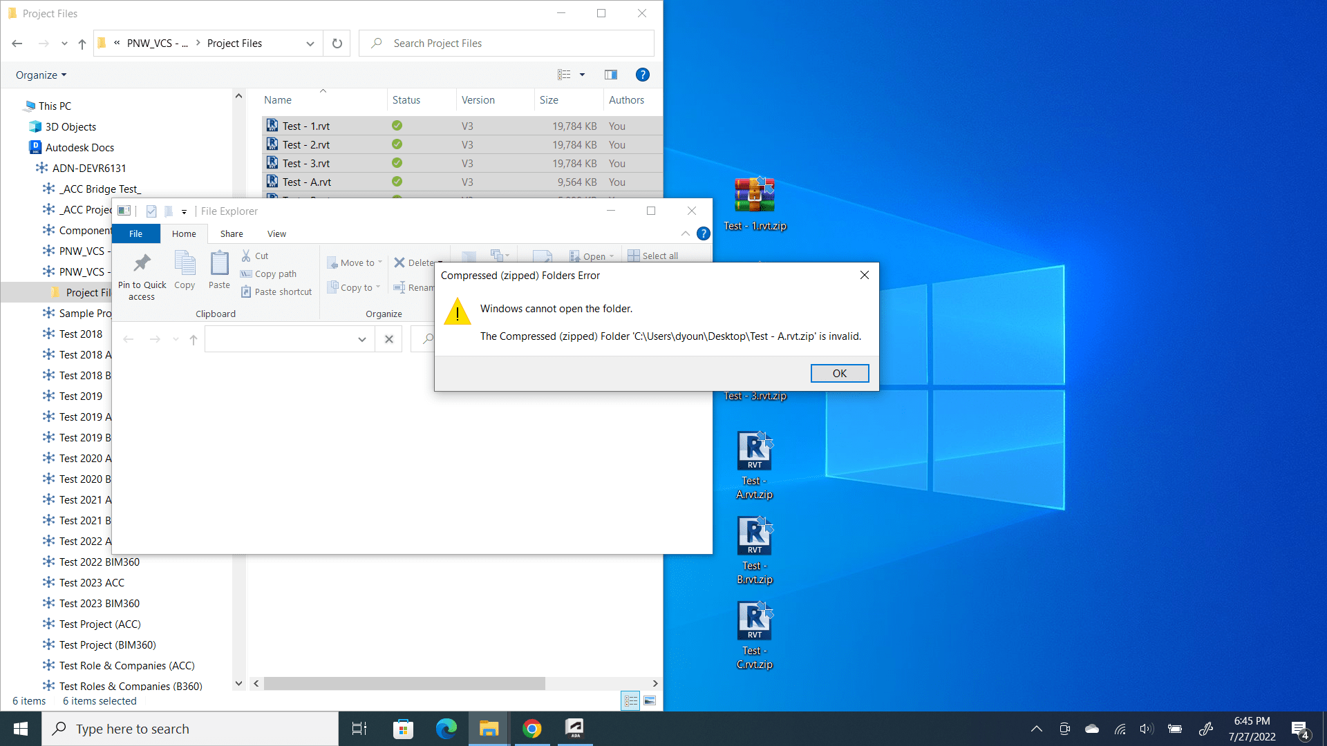
To further complicate matters, Desktop Connector displays all the files as RVT files even though some are ZIP files. Here’s how to test that out. First, we’ll use Windows File Explorer to select and copy all the files to the desktop. You can see the first hints of something being wrong in the following image…
Notice that all the files are named RVT just like was displayed in the Web Interface of BIM360 / ACC. However you can also see the icons are different between the two sets of files. The Revit files display their preview. The others display the icon because if the RVT extension because it can’t find a Revit preview. So let’s test our theory that some of these are actually ZIP files named wrong.
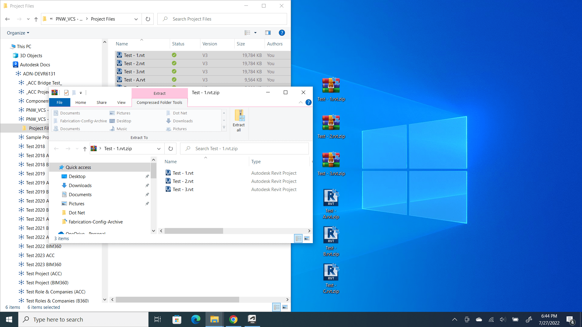
We’ll rename all the files to the ZIP extension and attempt to open them. The following images shows the renamed files. It also shows happens when you attempt to open the ZIP for one of files from Set 1 (Test – 1.rvt, Test – 2.rvt & Test – 3.rvt).
You can see when attempting to open the file TEST – 1.rvt.zip (remember we renamed to a ZIP) it shows the contents. It contains the Revit file and the links that Revit file uses.
Now let’s try the same thing with another file. This time. we’ll use the file Test – A.rvt.zip from Set 2.
You can see that despite renaming the file as a ZIP file, Test – A.rv.zip will not open and displays no contents. That’s because it is indeed not a ZIP file.
Summary of the Desktop Conector Problem
To summarize what we just saw, the web interface to BIM360 / ACC as well as Desktop Connector showed that all the files were RVT files. But upon testing with 2 different methods (web download & copy/rename from Desktop Connector) we can see that the two sets of files are not the same.
Set 1 is comprised of ZIP files despite showing their name as RVT and Set 2 are actual RVT files.
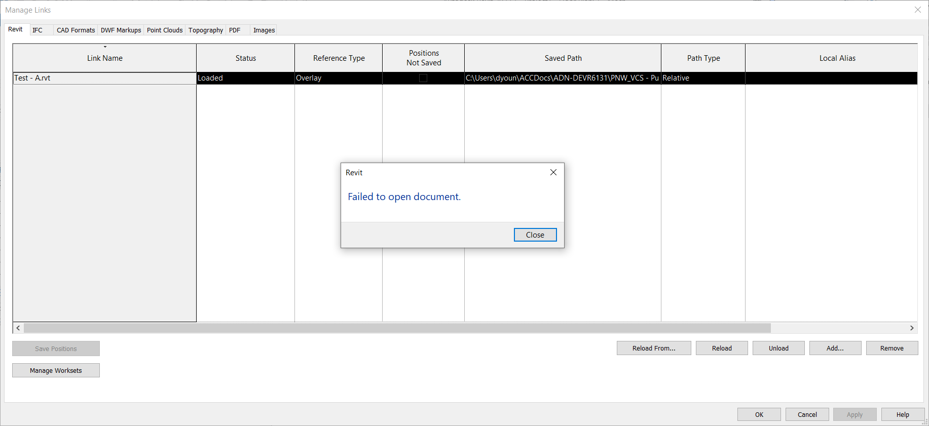
We can perform one further test to see if this is the case, We can start a new Revit file and try to link one of each set from the Desktop Connector. The following images shows just that…
You can see we were able to successfully link Test – A.rvt (from Set 2) using the Desktop Connector. But when we try to link Test – 1.rvt (from Set 1) we get an error, Failed to open document.
Again, this is because despite what you see (the RVT file extension), the file is actually a ZIP file. This is the root of the problem with using Desktop Connector to link Cloud Models. Linking non-cloud Revit models is not a problem. More in that in the next section when we cover “How” and “Why” this happens.
The How and Why
The issue of when BIM360 / ACC is using a ZIP file vs. a RVT file behind the scenes is actually quite predictable and a little controllable. So let’s take a look. It might be a little difficult to understand but we’ll try explain anyway. We’ll then follow-up with the steps to do it yourself.
At the root of the issue is that the Cloud model Revit uses is a separate file that the one you see in BIM360 / ACC Docs and Desktop Connector. You choose when to “publish” the one that shows up in BIM360 / ACC. And here’s where it starts to get complicated. We’ll use the names of the samples models to make it a little more clear.
If you have cloud model Test – 1.rvt open, and you link to cloud model Test – 2.rvt, if cloud model Test – 2.rvt has changes that are unpublished to BIM360 / ACC Docs when you publish Test – 1.rvt to BIM360 / ACC Docs, Test – 1.rvt will be a ZIP file.
On the other hand, if you link to cloud model Test – 2.rvt and it’s latest version is published to BIM360 / ACC Docs then when you publish Test – 1.rvt and download it, it will be a RVT file.
Did you catch that? Whether a Cloud model ends up as a ZIP vs. a RVT depends on the Publish Status of the Cloud models it links when you publish it.
Let’s look at that visually. The below image shows the 3 models from Set 1. Notice how none of them have the current version published. When you publish one of these, or even all three of these you’ll end up with a ZIP file.
Again, the issue is that you linked a cloud model in Revit when that cloud model had unpublished changes. Even if you published all of the models now, you’ll still get ZIP files with downloads and Desktop Connector. That’s because when they were published, there were unpublished changes which made them ZIP files. Further publishes will always make more ZIP files because they now reference Cloud models who’s Published versions are ZIP files not RVT. Yea…that’s a bit complicated. Just know that once you start getting ZIP Downloads, they’ll stay that way. From here on out, there’s only one way to fix it which we’ll get to momentarily.
How Not to get a ZIP
Now here’s where the process get’s slightly different if you want a RVT. The difference here is when you go to link the Cloud model, you need to make sure the file(s) you’re linking don’t have unpublish changes when you publish it. So when you have Test – A.rvt open, make sure Test – B.rvt doesn’t have unpublished changes, if it does, Test – B.rvt needs to be published beforeTest – A.rvt. Then when you then publish Test – A.rvt it will download as an RVT and Desktop Connector will be a ‘real’ RVT file.
So that sounds simple. Just make sure when you link the cloud model that’s it’s most recent version is published. But it’s not that simple. At any point in the future if one of the linked files is not published when you publish the model, you’re back to the ZIP file again and it stays that way. Until you fix it.
Unzipping the ZIP
If you ever link a cloud model that has unpublished changes you’ll end up with ZIP files. Further more, if at any point you publish you model, any one of the linked cloud models has unpublished changes, you’ll get a ZIP file again. And it won’t get fixed again easily.
This is why you should NOT link to cloud models from Desktop Connector. Because you’re relying on the author to understand this and know what to do. In fact, in the course of a real project, it’s damn near impossible to make sure you’re not going to get a ZIP. You can’t control when the project teams make changes and publish.
However, if you do want to fix the ZIP problem, here’s the process.
Open your Revit model and “unload” (not remove) and cloud model links. Save/Sync and publish the model.
Repeat Step 2 for all of the linked Cloud model. Make sure none have the links loaded.
Once all models have their links unloaded, republish them all.
Reopen one of the models and reload the links. Save/Sync the model. One model only.
Now Publish the model and wait for publish to complete before doing any more models.
Repeat steps 4 and 5 for the remaining models.
So that’s the process to “fix” the issue. Each model needs to be republished with none of the cloud model links loaded. You then open one, sync and publish each model. If you do save/sync more than one model before publishing again, you’re back to the ZIP files.
Try It Yourself
This issue is a bit nuanced…what makes a ZIP files vs a RVT. An even when its a ZIP, The web site and Desktop Connector misleadingly tell you it’s an RVT. And if you do have it working, it’s still fragile and breaks easily. Which is why it’s recommended to NOT use Desktop Connector to link to Revit Cloud Models.
If you really want to understand the issue, it’s best to try it yourself. You can do it with just 2 files. Here’s how. Follow these steps exactly.
Step 1 – Create file A in Revit and save as a Cloud model or Cloud Workshared model.
Step 2 – Close file A.
Step 3 – Create file B in Revit and save as a Cloud model or Cloud Workshared model.
Step 4 – Close file B.
Step 6 – Open file A and link file B using the “External Resources” (not Desktop Connector)
Step 7 – Save/Sync file A and close.
Step 8 – Open file B and link file A using the “External Resources” (not Desktop Connector)
Step 9 – Save/Sync file B and close.
Step 10 – Publish both files so their latest version appear in BIM360 / ACC Docs.
Step 11 – Try downloading with model from the web and you’ll see they’re zip files.
– – You’ve now recreated the process which makes the ZIP files – –
Step 12 – Open file A and unload the link to file B.
Step 13 – Save/Sync and Close file A
Step 14 – Open file B and unload the link to file A.
Step 15 – Save/Sync and Close file B.
Step 16 – Publish both models. (when you publish doesn’t matter with links unloaded)
– – Both models are now published with no Cloud model Links. This clears the ZIP issue. – –
Step 17 – Open file A and reload the links to file B.
Step 18 – Save/Sync and Close file A.
Step 19 – Publish file A and wait for it to complete before continuing. This is important. It’s linked to a file B. While file B has no links loaded, it has all it’s changes published (the critical step)
Step 20 – Open file B and reload the links to file A.
Step 21 – Save/Sync and Close file B.
Step 22 – Publish file B and wait for it to complete before continuing. This file is linked to file A which does have links, but it also has all of it’s changes published too.
Step 23 – Try downloading the models now. You should get a RVT file instead of a ZIP.
– – Both models are now published but are now accessible from Desktop Connector or downloadable as RVT files – –
It sounds like a lot of steps but it’s fairly quick to do. Perform these steps and you’ll get a better idea how the issue. Any time you have changes in multiple models before you publish, you’ll see the ZIP show up. If you change and publish a single model at a time, you’ll have RVT files. But also note, once you get the ZIP files, you’ll need to unload the links on all the files, republish and then open, reload and publish one at a time to clear the issue.
Summary
So that’s it. If you understand the issue, you’ll see how easy it is to have the ZIP issue show up. And that’s when linking from Desktop Connector breaks. And in the course of a project, it’s easy for others doing what I’ve explained above to break YOUR link to THEIR model when you use Desktop Connector.
So don’t use it to link Revit Cloud models if at all possible. If you’d like further reading on this, check out these Autodesk Knowledge Base articles…
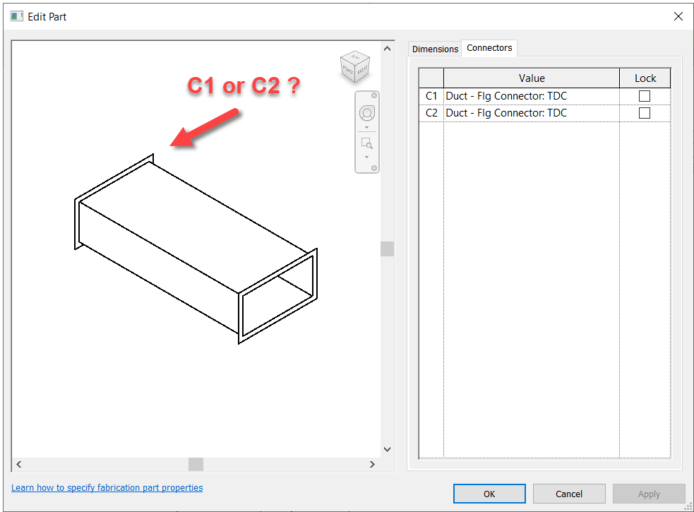
Fabrication Parts in Revit allow you to edit their connectors just like in CADmep. However, unlike CADmep, you can’t simply hover over a connector to determine if it’s C1 or C2.
So if you need to change a connector, you’re essentially guessing which one to change. Trial and error is at best 50% unless you’re lucky.
So how can you improve this “guessing” based workflow?
Thankfully I have a great network of people smarter than myself. I often get the credit for sharing the information but really, the credit belongs to those who show me. In this case, two of my industry friends showed me ways to improve the odds.
Method 1 – Slope
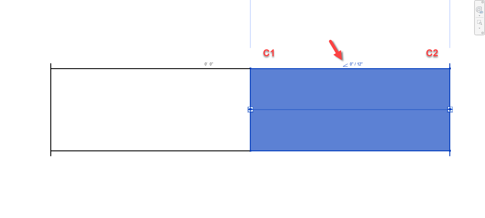
For this first method, credit goes to Liz Fong from MacDonald Miller. When you place a piece of straight pipe or duct, when you select it you’ll see a Slope indicator (< or >). This by default points to the C1 connector.
Duct/Pipe placed defaults the Slope symbol pointing to C1
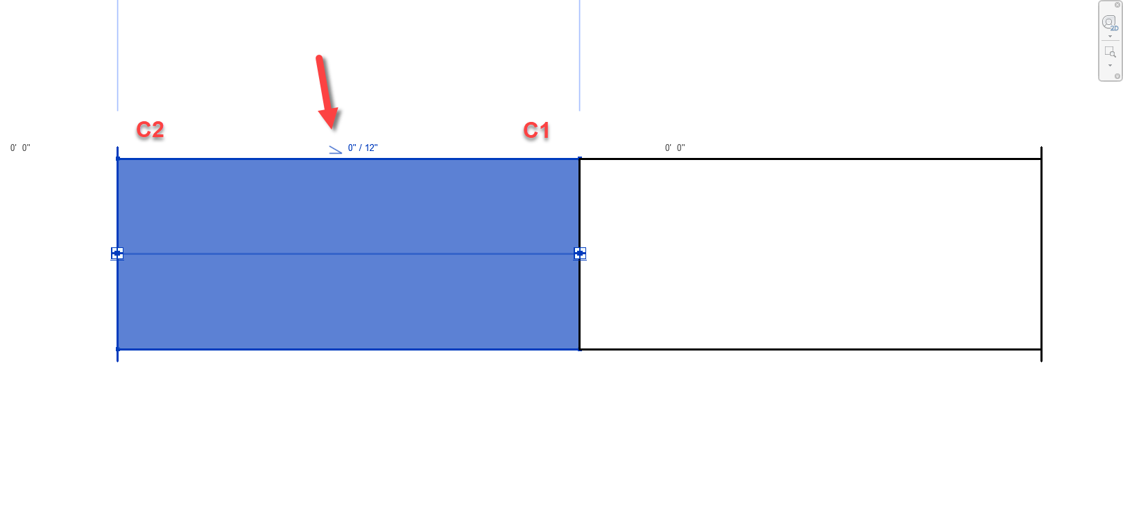
Duct/Pipe mirrored also defaults the Slope symbol pointing to C1
There’s a couple downsides to this approach that may apply in some scenarios….
This doesn’t work for fittings. Only Straight Pipe/Duct.
If you click the Slope Symbol, it changes direction and is no longer accurate.
This should really only affect Plumbing or sloped Grease Duct systems. Otherwise there’s not a lot of reason to change direction on a non-sloped system.
Symbol could still be accidentally clicked and reversed anyway and then be wrong.
Once changed, Slope symbol direction is remembered and there’s no good way to “reset” it.
Still, despite the downsides of this approach, I’m going to go out on a limb and suggest that even on a plumbing system, less that 50% of the slope symbols will be changed from their default. This alone makes this method better than a 50/50 guess like before.
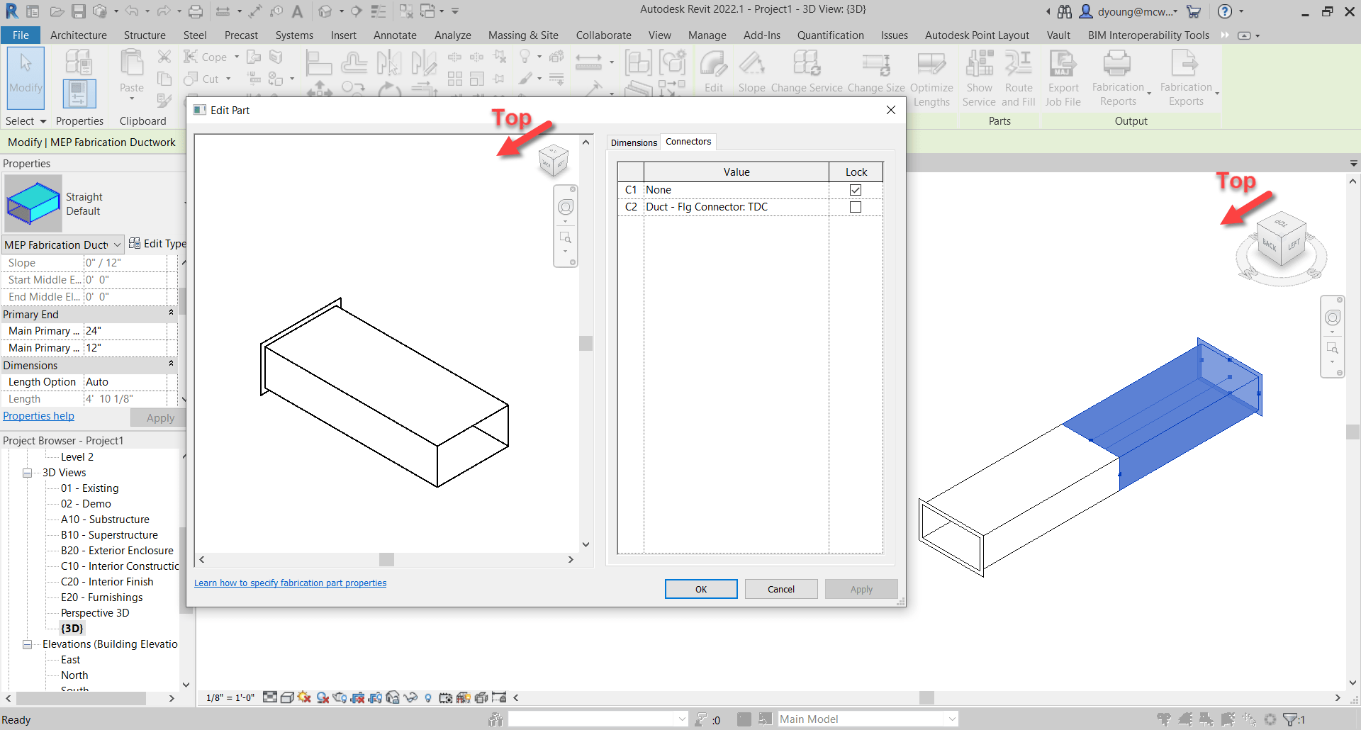
Method 2 – View Cube/Viewing Direction
This next method takes slightly more work, but is almost 100% accurate. Credit for this method goes to Alina Y. from JH Kelly.
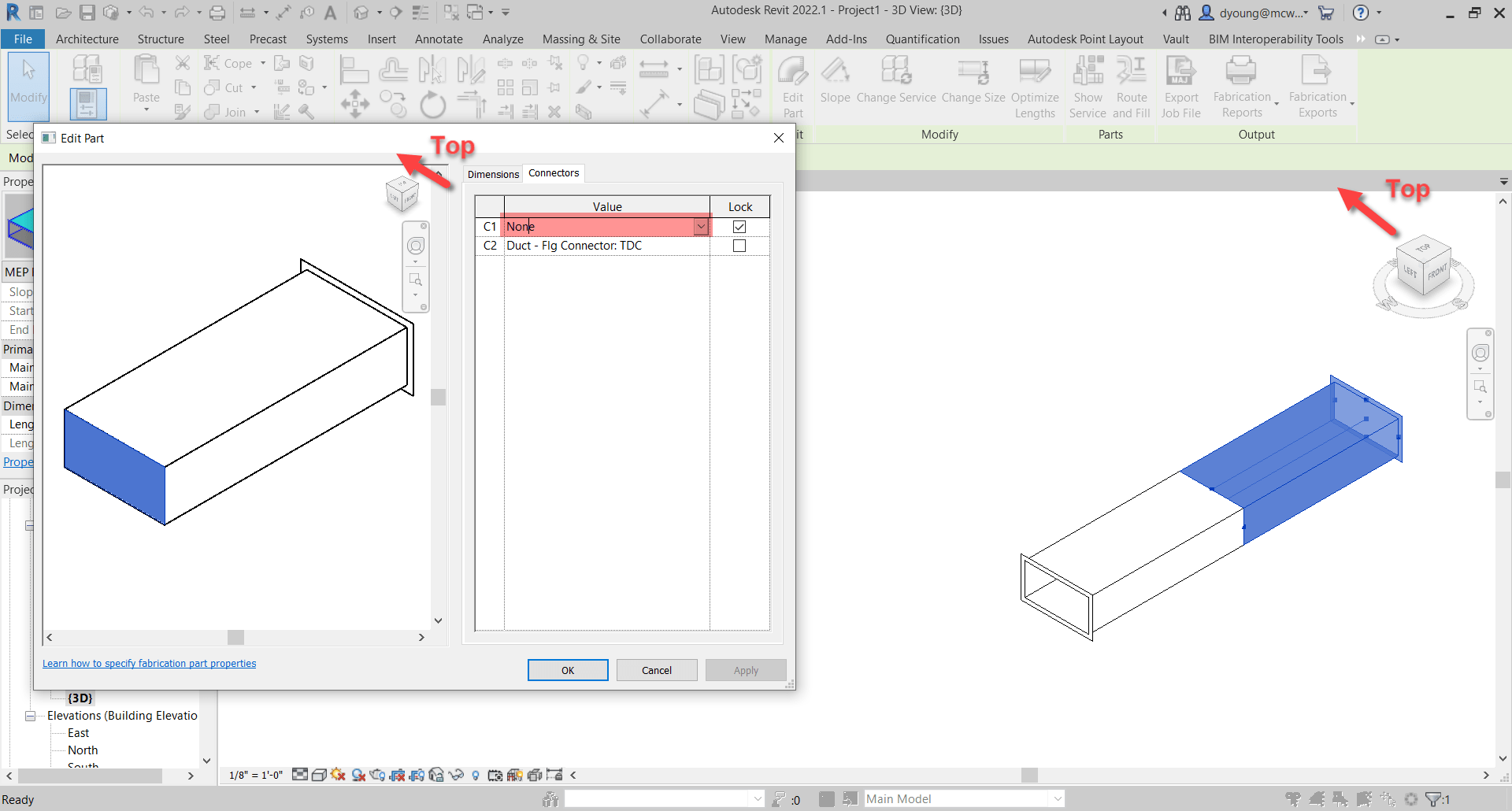
In short, from a 3d view, if you make sure the View Cube in the Part Editor window is aligned to the Revit View you’re in, the fittings is oriented in the same direction in the editor as in Revit. You can then select the connector in the Part Editor window and it highlights the connector end associated with it.
Duct/Pipe placed in Revit matches the editor when View Cubes are aligned. Selected Connector highlights.
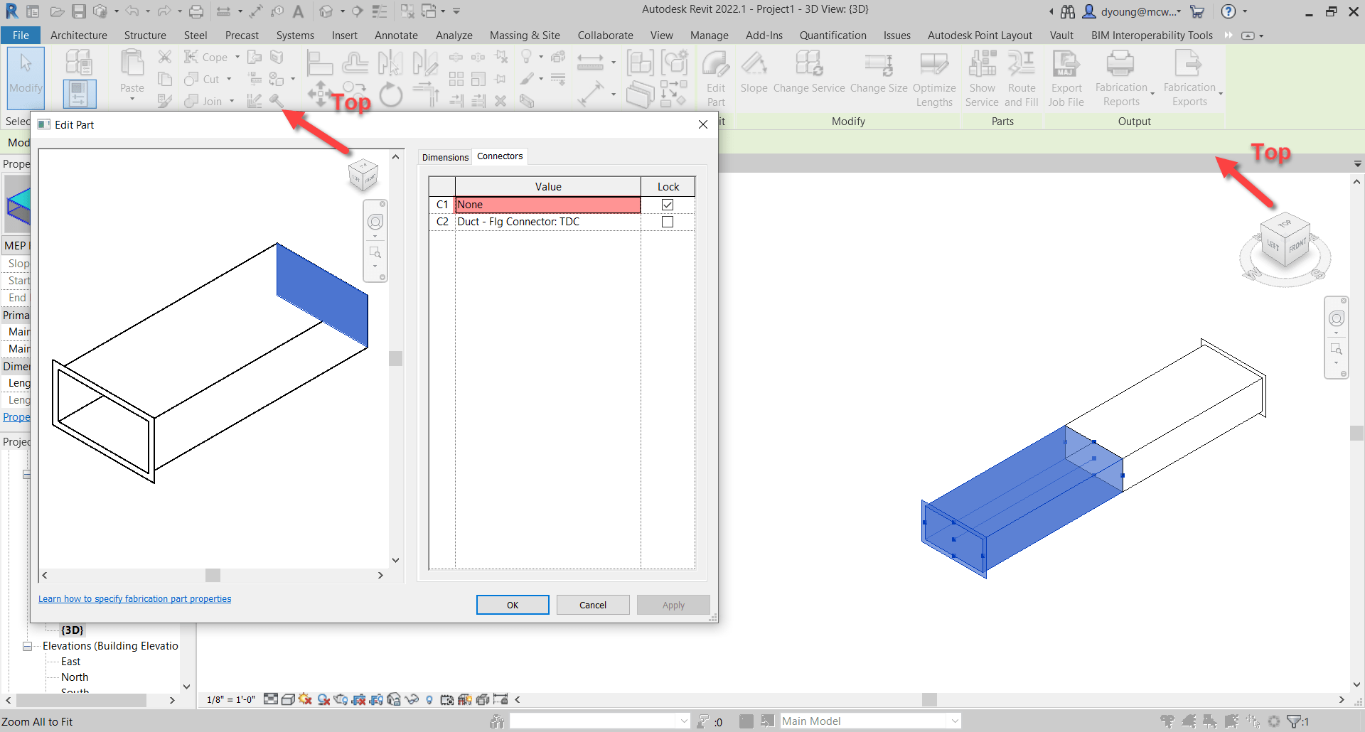
Duct/Pipe mirrored in Revit matches the editor when View Cubes are aligned. Selected Connector highlights.
This method is almost fool proof and has a few benefits over the sloped method we showed earlier.
Works on Fittings in addition to Straight Duct/Pipe.
Slope direction doesn’t matter.
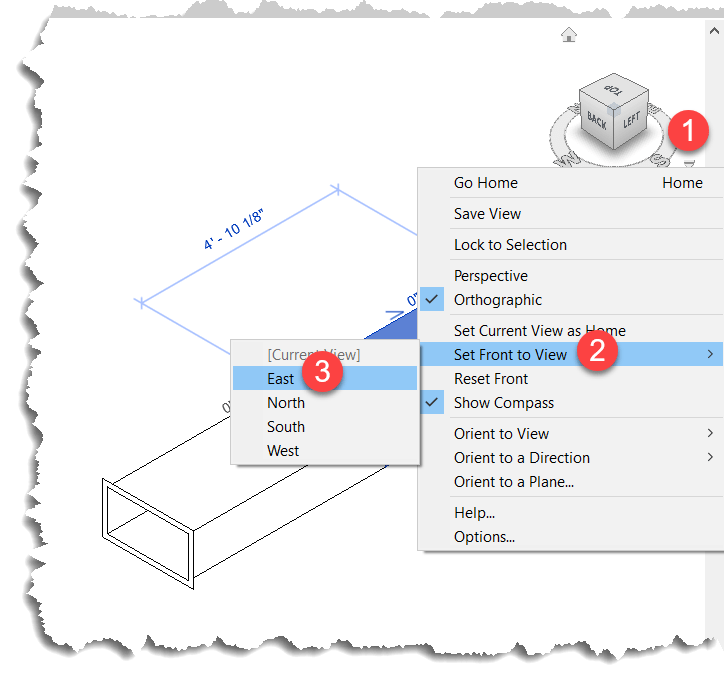
But we did say Almost. Where this method fails, is if the View in Revit is redefined.
When you set a new Front View, the view in Revit no longer matches the orientation in the Part Editor window as seen in the following image…
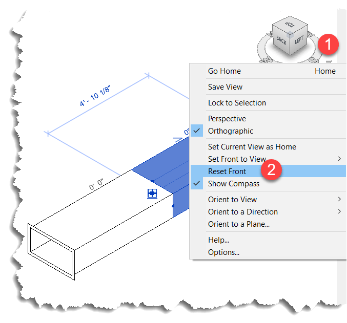
Luckily, this is easily remedied by simply resetting the Front View in Revit.
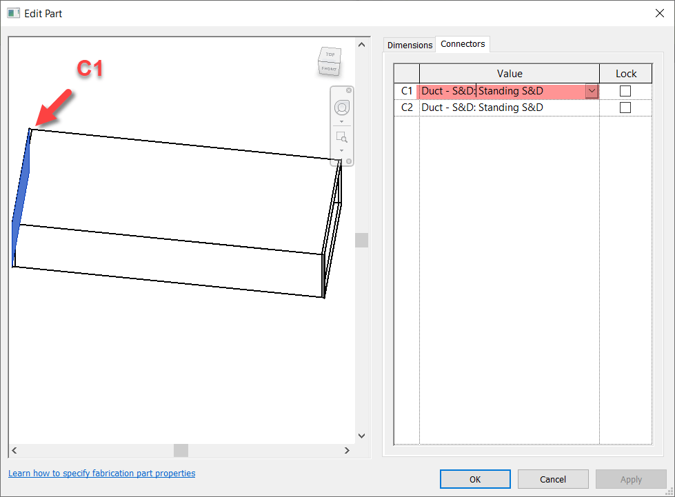
This method also works in Plan and Elevation Views with a slight twist. There’s no View Cube in the Revit window so it’s up to you to understand which viewing angle Revit is in. Next, you can make the View in the Item Editor match but when you look at a connector straight at the edge, you don’t see it highlight. You can then hold the SHIFT key and use the Middle-Mouse Button to slightly rotate the view so that you can see the connector that’s highlighted.
Here you can see what that looks like…
Summary
While not as quick and efficient as hovering over a connector in CADmep, either of these methods or even used in combination can increase your odds of changing the Correct connector on the first try.
While method #2 is more fool proof than method #1, there’s a reason I explain both and here’s how I’d use them both.
For non-sloped systems, the chances the slope symbol is reversed is very low. Because you’re likely selecting the part anyway to edit a connector, a quick glance is all you need to know which connector to change. Quick and easy for straight part on non-sloped fittings. No fuss. No muss. In this scenario, Method #1 is super quick.
For fittings and sloped systems, I would then shift to Method #2. Take a little more time, but it’s certainly quicker than being wrong 1/2 the time and then undoing the connector you just changed and then changing the other. That “trial and error” method results in 3 connector changes when you guess wrong. This is where Method #2 really shines…you get it right every time. If you’re Front View happens to be redefined, it’s easily rest.
Thanks again to Liz Fong (MacDonald-Miller) and Alina Y (JH Kelly) for their great input in coming up with these methods. They’re two of my favorite “Go To” people when I get stumped or need a little help orienting my thoughts.
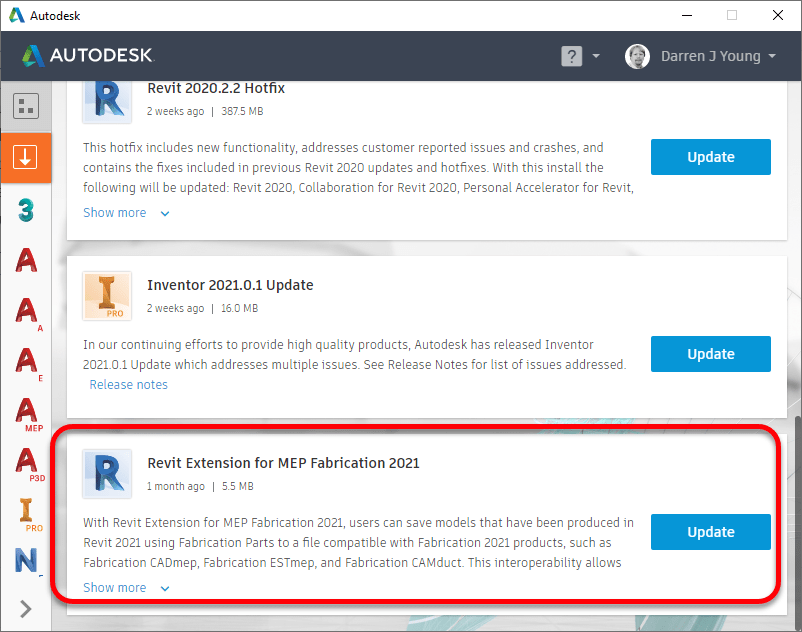
Update (2020.04.08): Autodesk released the Extension for MEP Fabrication 2022 on April 8th. You can get it from the Autodesk Desktop App or from your Autodesk Accounts Portal (manage.autodesk.com). This restores the MAJ Import/Export functionality and access to Fabrication Reports. It does NOT install the RME to FAB add-in. So part of the below guidance is still needed. You’ll want to copy the ADSK_Export.addin file per the below instructions. The other file is no longer needed and Autodesk’s newly released Extension will overwrite what’s needed if you used the below guidance.
If you’re an Autodesk Fabrication user and loaded up Revit 2022, you may have noticed some key Fabrication Add-ins are missing. It happens most every release. Deadlines for product releases always trump add-ins. This year, all the installers were reworked too so there was extra work I’m sure.
Don’t fear, they’ll get to them eventually. Just keep an eye on the Desktop App for when the updated Add-ins are release. In the mean time, here’s a temporary fix…
Enabling Fabrication Add-ins
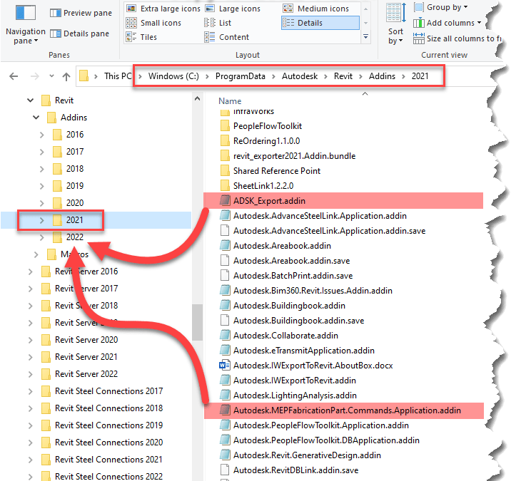
To get the Fabrication Add-ins, you’ll need Revit 2021 installed and have those add-ins loaded in there. From there, there’s 2 files you’ll need to copy to a different folder.
The first file enables MAJ Import/Export and Fabrication Reports. The second file enables the Fabrication RME Extension in the Add-ins Ribbon.
You copy them from this folder…
C:\ProgramData\Autodesk\Revit\Addins\2021
…to this folder…
C:\ProgramData\Autodesk\Revit\Addins\2022
Here’s what that looks like in Windows Explorer….
What This Looks Like in Revit
Once you copy those files, restart Revit to see the changes. Here’s a review of what that looks like…
MAJ ExportsMAJ ImportFabrication Reports
A Parting Word
It should be noted that this work around should be considered “temporary”. You’re running 2021 Add-ins in 2022. The files you coped should be removed once the official 2022 Add-ins are released. This will ensure you get any fixes they may have added to the 2022 versions.
If you’re looking for a one stop shop for some of the Revit / Autodesk Fabrication resources which I recently spoke about during a recent MCAA Education series Webinar, you can them all wrapped up in this tidy page here…
Most MEP contractors moving to Revit with Fabrication Parts at some point wrestle with renumbering parts. You can purchase tools or add-ins to make this easier or even write your own with Dynamo or C#.
But most contractors aren’t coders. And buying more software can also be a challenge. The good news is that those are not your only options, There’s some well written FREE Revit Add-Ins that make this a breeze.
Required Tools
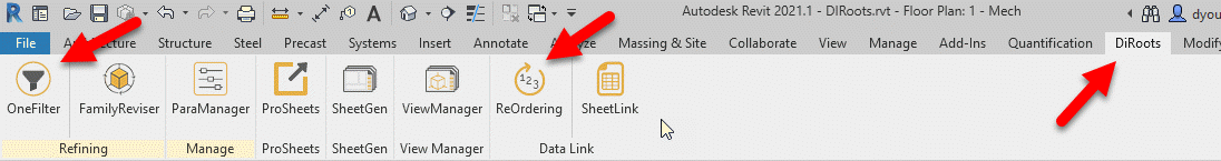
Head over to DiRoot’s web site (https://diroots.com/) and download the OneFilter Add-In found here and the ReOrdering Add-In found here.
Once installed, you’ll find the tools in the DiRoots Ribbon in Revit along with any of their other tools you may have installed.
Getting Started
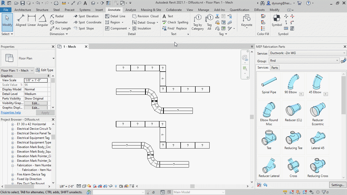
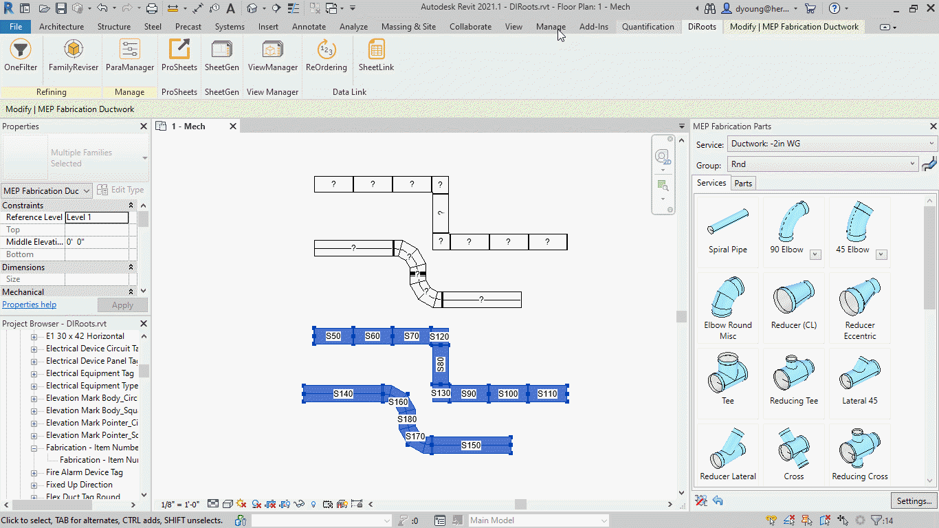
The following image shows 2 runs of Rectangular and 2 runs of Round duct work drawn in Revit using Fabrication Parts. One is drawn in a +2in WG service and the other -2in WG service. All duct has a tag configured to display the Fabrication Part’s Item Number property.
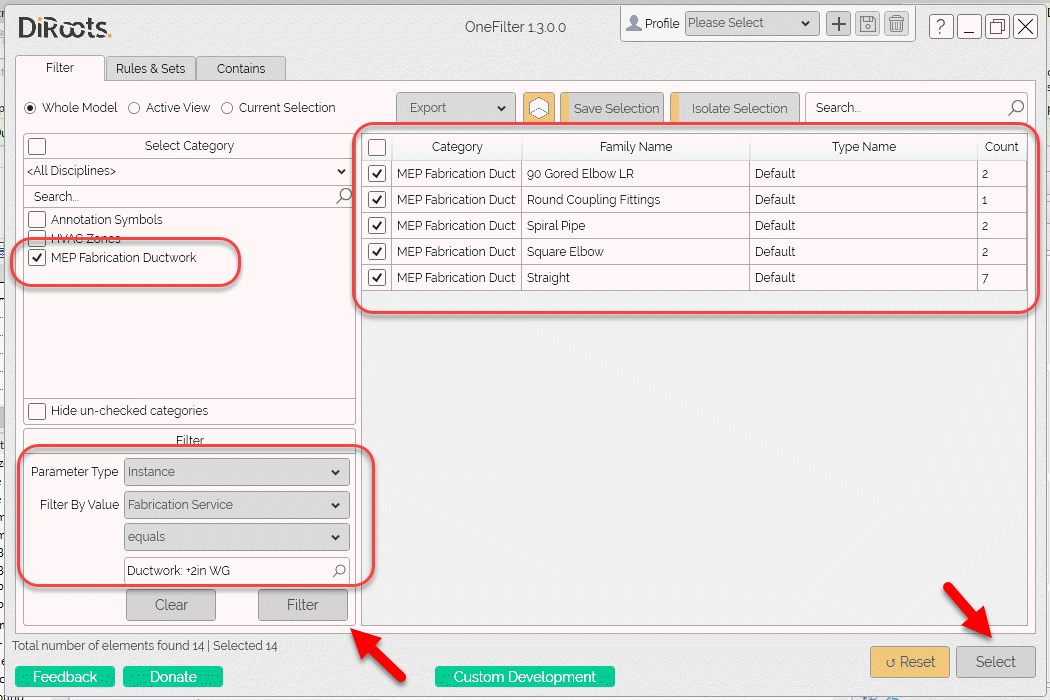
First Up – DiRoots OneFilter
Using the DiRoot’s OneFilterAdd-In, you can easily select not just Fabrication Parts, but also select them based on their properties.
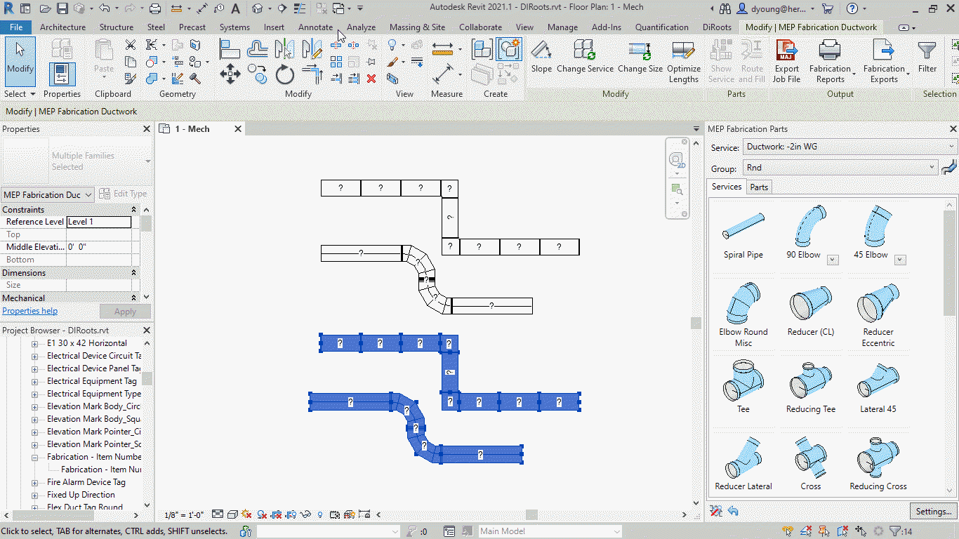
Once selected, you can see Revit selects the specified items in your model.
Next – DiRoots ReOrdering
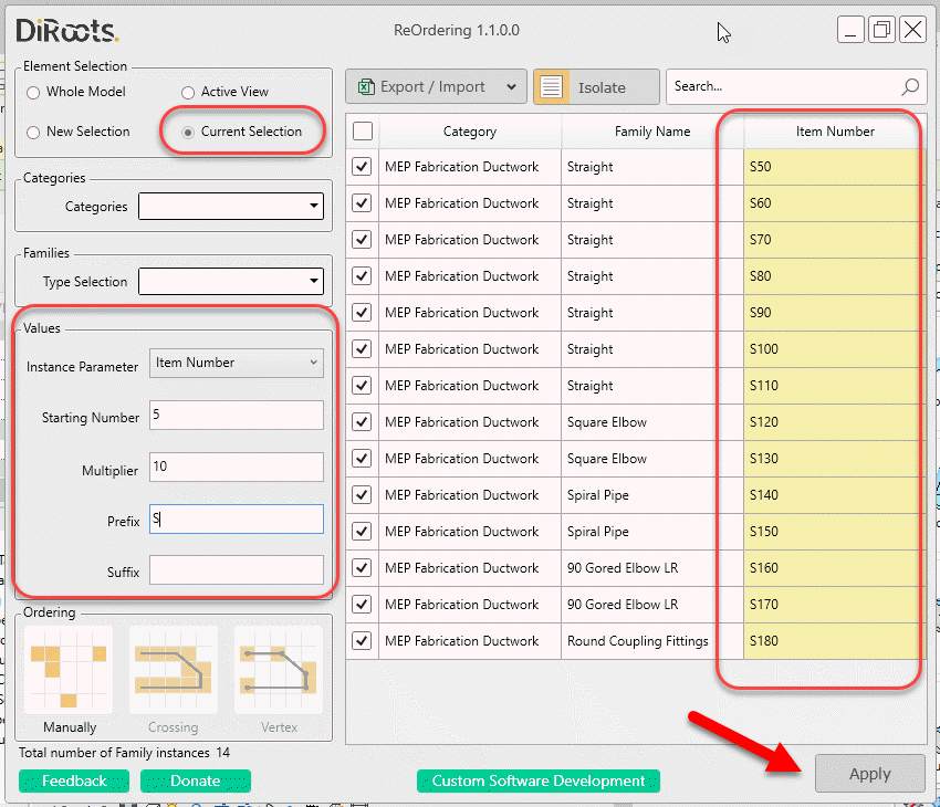
Now that your desired parts are selected, you can use the DiRoots ReOrdering Add-In to renumber those parts.
After applying your renumbering parameters, you can see how Revit then displayed the updated Item Numbers for the Fabrication Parts.
Wrapup
As you can see, with a couple free (well written) utilities you can quickly and easily select and renumber your fabrication parts in Revit.
There’s a lot of other reasons beyond renumbering to use some of these Add-Ins. They’re very functional for a lot of workflows. Those uses are beyond the scope of this post but feel free to explore these Add-Ins or some of the other DiRoots tools when you get a chance. They’re some of the highest quality free Add-Ins for Revit than you’ll find anywhere.
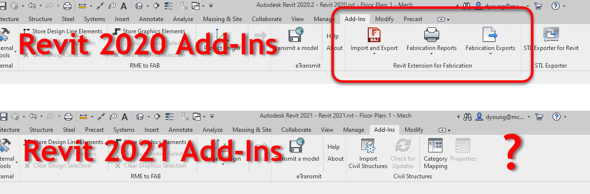
Have you tried to Import or Export an MAJ file in Revit 2021? Have you tried to run a Fabrication Report or Export in Revit 2021? If so, you may have noticed that it’s not in the Add-Ins ribbon any longer.
Your first thought might be you need to install the Revit Extension for MEP Fabrication 2021. But even after installing, it’s still not there. You might then be tempted to submit a support ticket to Autodesk to help troubleshoot your install. No need. Autodesk simply moved the commands and made them more integrated to Revit.
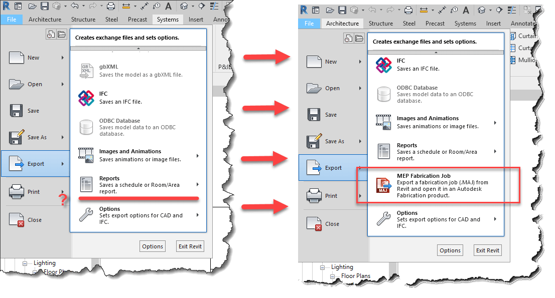
MAJ Exports
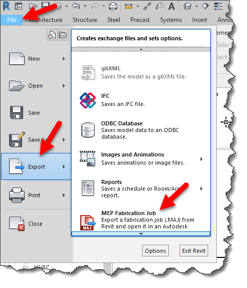
MAJ Exports can now be found in two locations in Revit 2021. The first location is under File -> Export.
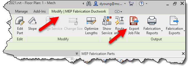
The second location shows up in the context ribbon when you select Fabrication Parts….
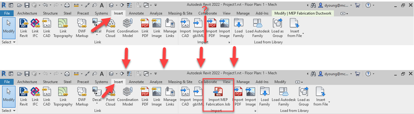
MAJ Import
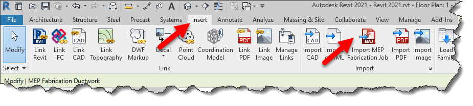
MAJ Imports have moved as well. This is a little easier to find if you think about it, it’s located under the Insert ribbon.
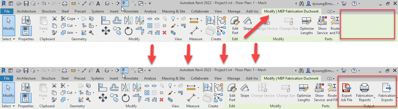
Fabrication Reports / Fabrication Exports
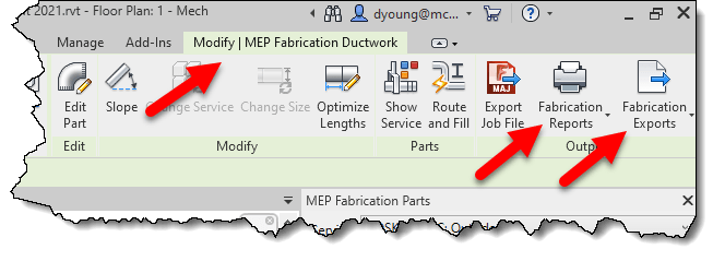
Your Fabrication Reports and Fabrication Exports will also show up in the context ribbon when you select Fabrication Parts.
Context Ribbon Doesn’t Show MAJ Export or Fabrication Reports/Exports?
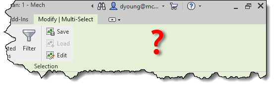
If you select parts in Revit and the context ribbon does not show the MAJ Export or Fabrication Reports/Exports drop-downs, take a look at the Ribbon’s title.
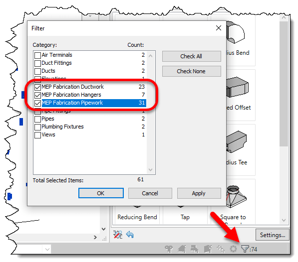
If the Title of the ribbon says Multi-Select, this means you have a more than just MEP Fabrication Parts selected. You can quickly filter your selection to just MEP Fabrication Parts using the Filter tool in the lower right of Revit.
Un-check all items except anything that begins with “MEP Fabrication …”. This will deselect any non-Fabrication Parts and your MAJ Export and Fabrication Reports/Exports tools will then show up.
Still Can’t Find These Tools?
Unlike prior years which required a separate install, Revit 2021 installs the Fabrication tools as part of the product install. However, if the tools somehow become uninstalled, and you don’t find them, you can reinstall them by downloading the Revit Extension for MEP Fabrication 2021 from your Autodesk Account. Alternatively, you should be able find it in the Autodesk Desktop App in the updates.
If you’re using Revit 2018 or 2019 with Fabrication Parts, you may notice that upon loading or reloading your configuration some (or many) of your parts become “Invalid”.
I’m not talking about Fabrication Parts whose CID/Pattern isn’t supported in Revit. I’m referring to perfectly valid Fabrication Parts. Parts that once worked. They may even be currently in your model but are no longer active in your Parts Browser. Here’s a couple examples…
You may even notice valid parts become invalid after unloading a service or that invalid parts become valid again after loading a new service.
What’s happening is that your Fabrication Configuration’s Image Cache has become corrupt. The issue is in Revit 2018 and 2019. Revit 2020 does not experience the issue. Whatever changed in Revit 2020 made it more resilient to a corrupt image cache.
The only known fix until recently was editing your service template. You would have to remove and re-add the part. Reloading the Fabrication Configuration in Revit and it would be fixed. Unfortunately, future database changes would often revert back to the invalid state.
Quick and Dirty Work-Around (Revit 2019 Only)
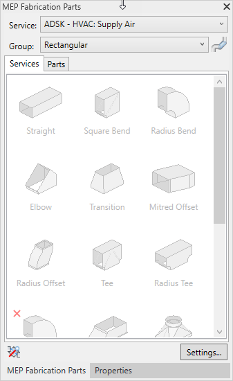
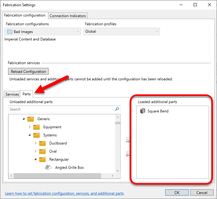
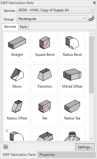
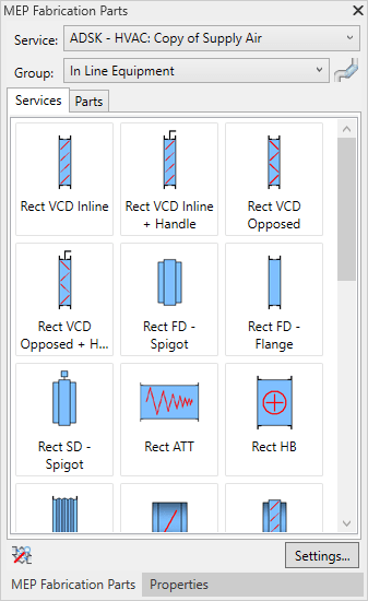
If you’re using Revit 2019, there is a quick and easy work-around. That’s assuming you only have a few parts that are invalid. To work around the issue, reload your Fabrication Configuration and individually load the invalid part in the Parts tab. The following image shows one invalid part added to the Parts tab.
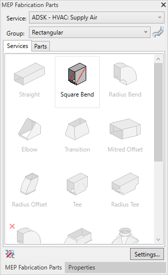
Once added, the Part then becomes valid in the Parts Browser.
A Permanent Fix (For both Revit 2018 & 2019)
The prior work-around was only available in Revit 2019. This didn’t help Revit 2018 projects which do not have the Parts tab in Fabrication Settings.
To properly fix the issue, you need CADmep. Load your Fabrication Configuration in CADmep. Once loaded, find an open area of your service and press CTRL+SHIFT+Right-Click and select Clear Cache.
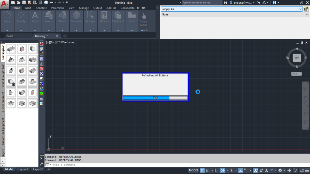
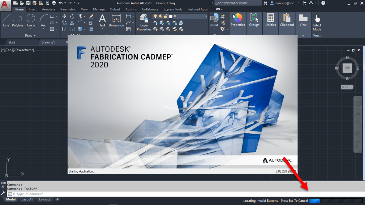
Next type the REFRESHALLBTNS command. You’ll see a progress bar while CADmep refreshes your button image cache.
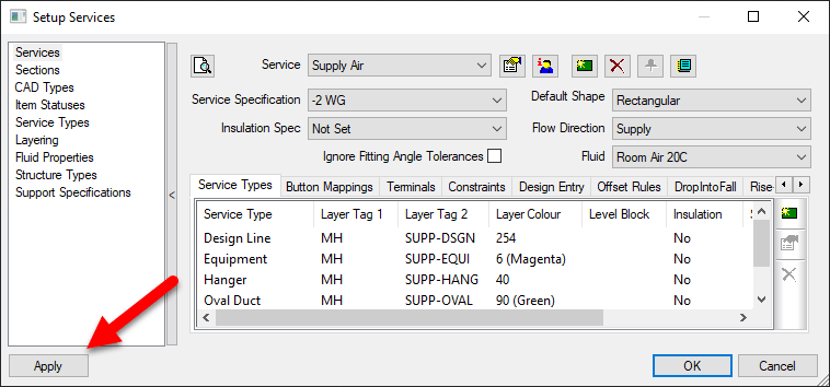
At this point, your button cache should be rebuilt. However I’ve seen instances where you have to “coerce” or otherwise persuade CADmep into saving it back to disk. To verify the changes are saved, go to the Service Editor and click the Apply button then close the dialog.
At this point, you should be all set. If you go back to the problem Revit file and reload your Fabrication Configuration, you should see the Fabrication Part become active again.
Preventing Future Corruption
To prevent future corruption, you first need to understand how it happens. When loading CADmep, you may have noticed the “Button Validation” as shown in the following image…
Because this can be a slow process, most users simply hit the Escape key to terminate the validation. This isn’t a big deal for a user. For a database administrator, this can leave your image cache partially built and corrupt it.
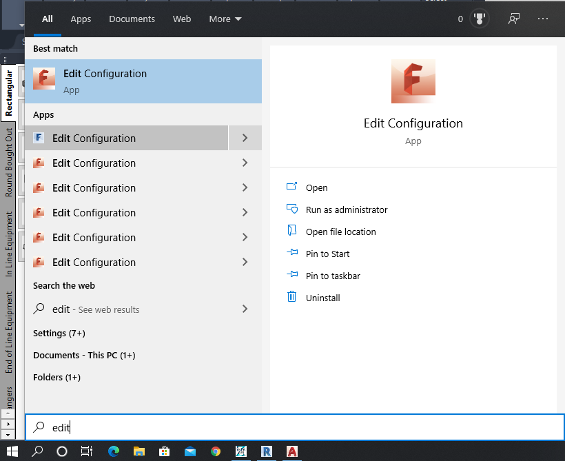
While you can simply stop canceling the process, the better option is to prevent it in the first place. By default, CADmep enables Button Validation. But you can turn it off. To do this, use the Edit Configuration utility that comes with CADmep.
Note that this utility is named the same between versions and between CADmep, ESTmep and CAMduct products. It may be tricky to pick the right one. You need to select the one that comes with CADmep.
You also need to perform this for each CADmep version that’s installed. To help, you may want to choose the Open file location option. This will bring you to the folder with the shortcuts. You can then easily navigate to the proper version of Edit Configuration that you’re looking for.
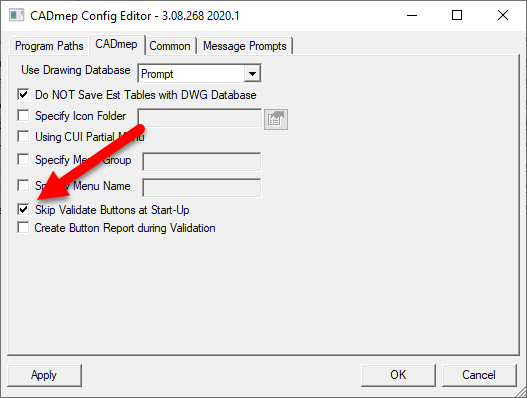
When you run the utility, it’ll prompt for a configuration. You can pick any, it doesn’t matter. The setting to change is not specific to the configuration, only the product and version for the currently logged in user. The following image shows the Skip Validate Buttons at Start-Up option.
Select this option and the next time you launch CADmep, you’ll no longer see the button validation. This prevents you from canceling out of the validation as well as speeds loading of CADmep.
Credit Goes To…
Special thanks to Martin Schmid and Craig Farish of Autodesk for helping with this issue. We’d been experiencing this issue on and off for over 1/2 a year. Autodesk Support had indicated that nobody else had reported the issue and provided the 2019 work-around. They repeatedly assured me it was fixed in 2020 and not a problem with my data. They had no fix for 2018 which is used by several projects.
After experienced a large volume of invalid buttons, our database administrator spent 6 hours before users arrived rebuilding service templates. The the issue resurfaced within hours of a simple database update. With $5k-10k of lost productivity over 2 weeks with several detailers unable to model certain services, I called in a favor with Martin and Craig. They quickly had their team analyse our data and identify the fix.
I’ve since run into 4 other companies experiencing the same issue and this fix has worked flawlessly for them as well. Hopefully you’ll not need it but if you do, it’ll save you load of time, frustration and money.