I’m occasionally asked how one would add one of every size in a product list to their job. This very easy using ESTmep or CAMduct. CADmep however does not have this capability.
Here are the steps….
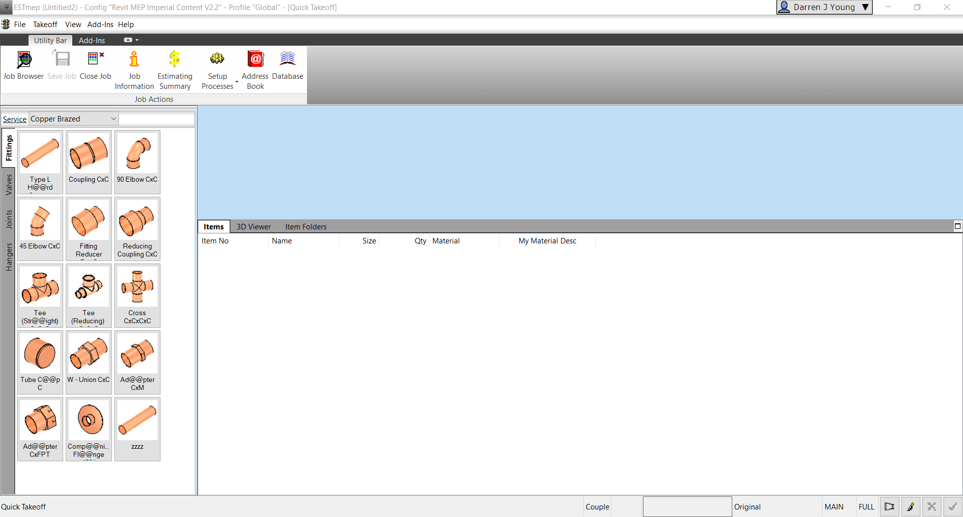
Step 1: Start ESTmep / CAMduct with a blank job.
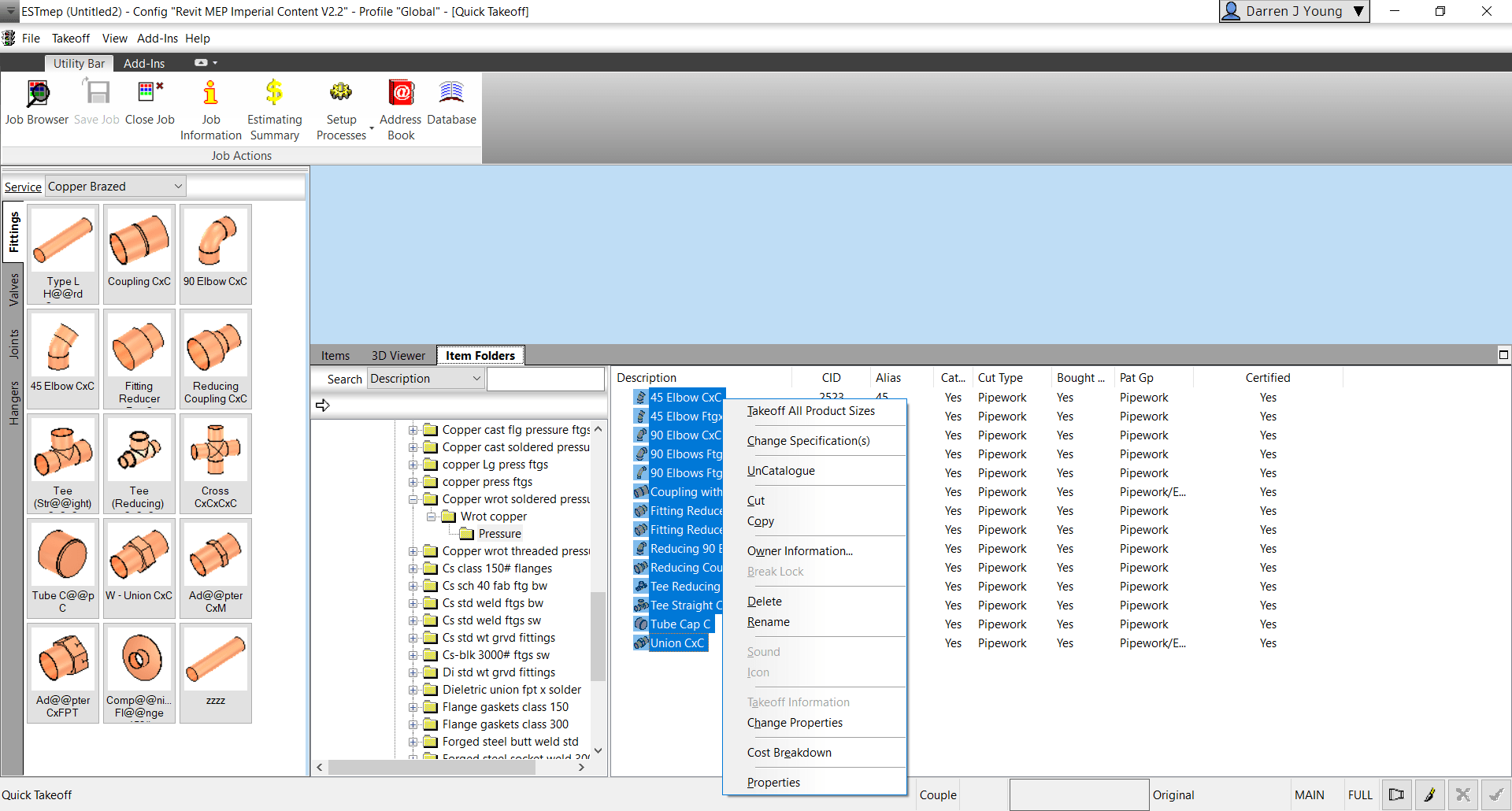
Step 2: Go to Item Folders and navigate to the folder with the ITM(s) you wish to takeoff all sizes for. Select all the ITM’s and press CTRL+SHIFT+Right-Click and select Takeoff All Product Sizes.
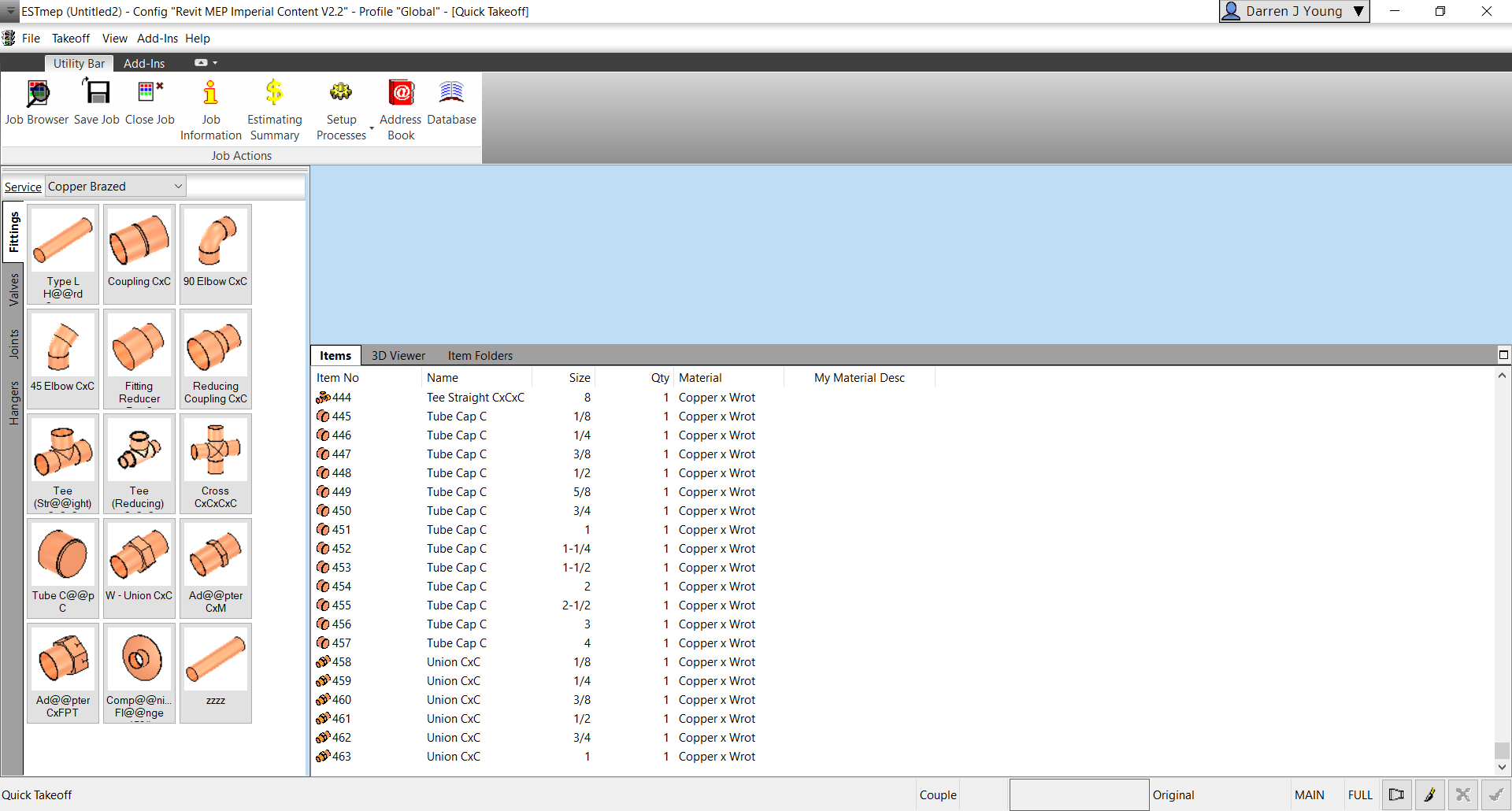
Step 3: Go back to the Items tab and review all the sizes of each item you selected.
Why Would You Do This?
There’s several reasons this may be helpful to you.
Any Size with dimensional errors is quickly found
A simple report shows you where you may have holes in your data (Price, Labor, Product Info, etc.)
Produce a quick MAJ that can be opened in CADmep (OpenJob) to measure each size to ensure dimensional accuracy.
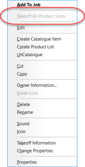
If the option is grayed out/disabled, you’re one or more of the ITM’s in your selection is NOT Product Listed. For this to work, all items you’ve selected must be Product Listed.
Seems obvious once you see it but sometimes the easy things are the most ellusive.
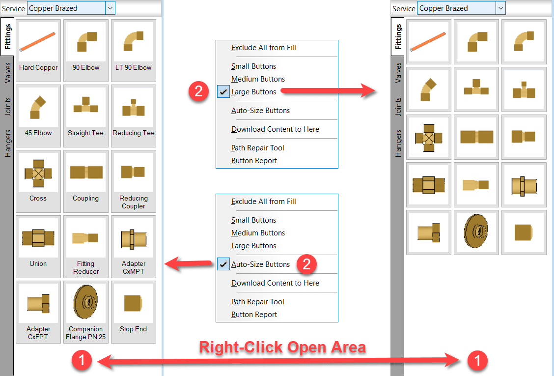
If you’re noticed descriptions on some of your computer’s fabrication palettes and not others, it’s likely the “AutoSize” option you’re looking for.
Right-Click on an open area of the service palette and select the option you prefer. This applies to CADmep, CAMduct and ESTmep. Revit…not so much. Revit likes to do it’s own thing.
One of the things that can make machine setup difficult in CAMduct is setting up the coordinate system. This coordinate system must reflect the actual configuration of the machine. Some machines can be reconfigured to swap the axes or set the origin to any corner. This lets you configure the machine to match the software. Others can’t be reconfigured and require you to configure the software to the machine.
It doesn’t really matter where the origin is on the machine, just as long as the configuration in CAMduct matches. Matching the machine isn’t difficult, just as long as you understand what’s happening.
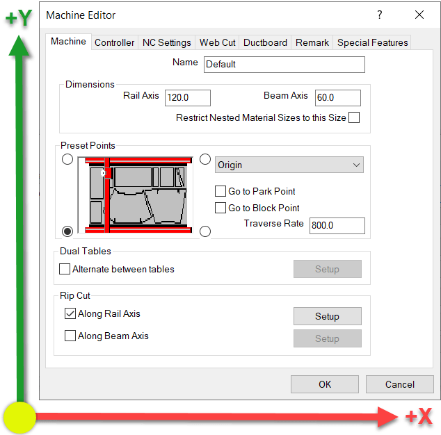
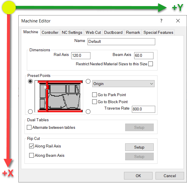
Default Origin and Axis Orientation
In the Machine Setup Dialog, the default Origin is in the lower left. Take a look at the settings and note the X-Axis and Y-Axis directions.
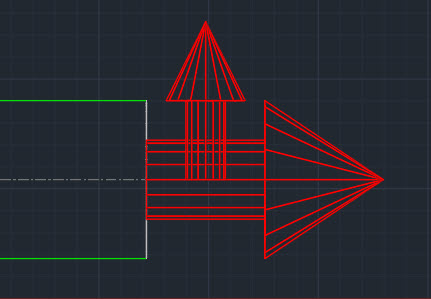
From this configuration, here’s a simulation of the code that’s generated.
If this configuration doesn’t work for your machine, it typically means the machine has a different origin and/or Axis configuration.
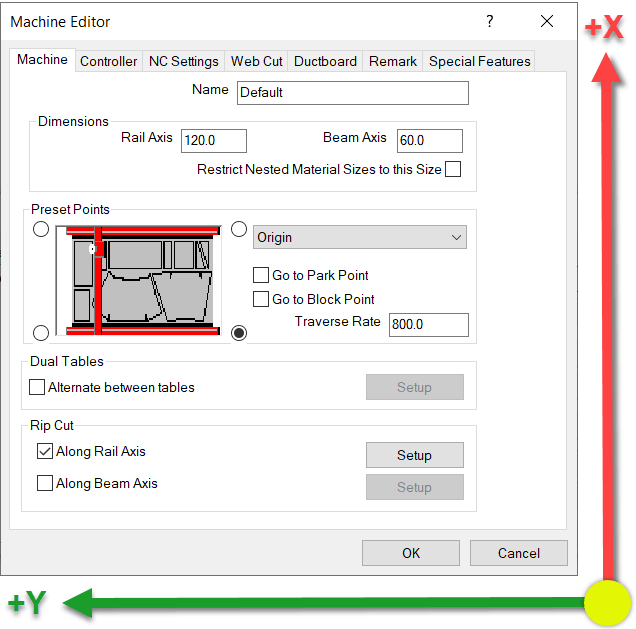
This next configuration rotates the coordinates which results of the X-Axis and Y-Axis being swapped. It also looks like the Origin location changes given the picture, but that’s not the case. This is why Machine Setup can be confusing. This picture does NOT change the origin location. This will become clear shortly.
With this configuration, you’ve now rotated the Coordinate System. When you look at the Simulation below, you’ll that the origin doesn’t actually move. The sheet is still oriented the same way. Long direction is the Rail and the Short direction is the Beam.
What you’ll notice here when looking at the code, is that the Part is Still oriented in the Lower Left Corner of the sheet. However, the X-Axis and Y-Axis are swapped. Additionally, looking at the code on the right, you’ll see how the Y-Axis goes into Negative coordinates. This also isn’t what most machines want, they typically work in positive coordinates but this is easily fixed which we’ll show a little later.
This next configuration sets the X-Axis and Y-Axis so that both are mirrored…or rotated 180 degrees.
Looking at the simulation of this configuration, you’ll see both X & Y Axes are using negative coordinates.
Here the both Axes are in negative coordinates and the Part is still located in the lower left of the sheet. Again, not what a machine wants typically, but easily fixed and covered in a little bit.
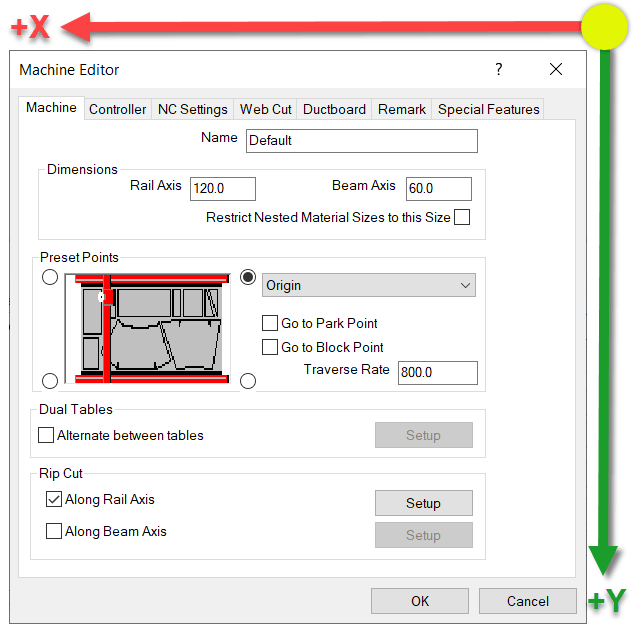
Here’s the last configuration. Again notice which way the Axes are oriented.
In this next configuration, the X-Axis and Y-Axis are reversed like before. But this time, the X-Axis is in negative coordinates where as the Y-Axis is in positive coordinates.
Fixing Negative Coordinates
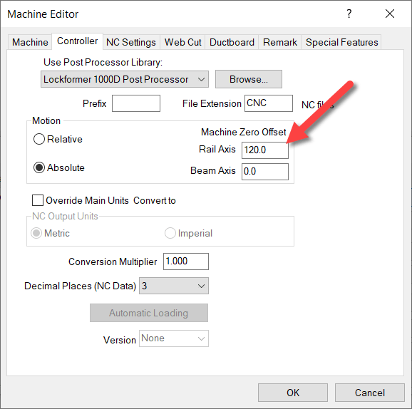
What makes this hard, is that the setting in the dialog makes you think you’re moving the origin of the code. You are not. You’re merely rotating the coordinate system. This is critical when using a machine tool like a Lockformer or Vulcan that uses Trimble’s TookShop controller (formerly called Vulcan). Those are a couple of the most common machines where the X & Y Axis are reversed.
When you look at the simulations, the sheet is still oriented in the same location and the part starts in the same location on the sheet.
You can look at the configuration and see that the Rail is set to the long direction and the Beam is set to the Short setting. Remember this….it’ll be important in just a bit.
For this example, we’ll again use the 90 Degree rotated configuration (our second example) where the X & Y are reversed and the Y-Axis coordinates are negative. You can see in the code, that the Y-Axis is the LONG sheet dimension due to the rip cut along the Rail that’s cut at the end of the program.
Because the Rail Rip Cut starts at Y=0.0 and goes to Y-120.0, you can see that the Origin is still on the left side of the sheet not the right as the configuration screen suggests. Here’s a reminder of the Axis directions…
So if cutting the Rip Cut on the sheet from Left to Right for 120 units means the coordinates go negative, it’s clear the Origin is on the left. To make those coordinates go positive, you need to shift the Origin to the right on the Beam (Y-Axis). You can do this on the Controller tab and entering the shift amount for the Rail.
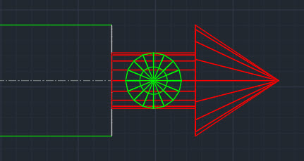
How, when you run a simulation on this setup, you’ll see the Y-Axis is still the long sheet direction, but they’re all positive coordinates.
Notice on the simulation that the part is STILL on the left side of the sheet and because we shifted the Origin to the right side the Rip cut along the Rail (long side) goes from Y=120.0 to Y=0.0.
You’ve now successfully swapped the X&Y Axis and corrected the coordinates to they’re all in positive units. From here, you can go back and finish configuring all your other preferences like where the parts get nested on the sheet, starting cut location, etc.
CADmep, ESTmep and CAMduct all use the concept of an Attacher. This is what tells Fabrication which way to route elbows and branches.
Most people know how to place and rotate the Attacher. There are a few other tricks to working with the Attacher that you may not know about.
Up or Down, How to Get Around
Depending on your view orientation, you may notice part of the Attacher turns from Red to Blue or Green. As you rotate the Attacher it’s color will change to indicate the direction the arrow is pointing.
Green = Grass (Attacher is pointing away from you)
Blue = Sky (Attacher is pointing toward you)
Rotation Tricks
Depending oh which program you’re in (CADmep, ESTmep or CAMduct) and the keys you press, the Attacher rotates differently. Here’s a chart explaining those nuances.
Rotation
Method
CADmep
ESTmep
CAMduct
90 Degrees CCW
Click
Yes
Yes
Yes
90 Degrees CW
Shift+Click
No
Yes
Yes
180 Degrees (Flip)
Ctrl+Click
Yes
Yes
Yes
15 Degrees CCW
Alt+Click
Yes
No
No
CADmep – Click Attacher to Rotate Counter Clockwise 90 DegreesCADmep – Ctrl+Click Attacher to Rotate 180 Degrees (Flip)CADmep – Alt+Click Attacher yo Rotate Counter Clockwise 15 DegreesESTmep / CAMduct – Click Attacher to Rotate Counter Clockwise 90 DegreesESTmep / CAMduct – Shift+Click Attacher to Rotate Clockwise 90 DegreesESTmep / CAMduct – Ctrl+Click to Rotate Attacher 180 Degrees (Flip)
Any sheet metal shop that CNC cuts their liner has likely configured their database to make seam adjustments in the liner developments. These settings are typically global and tell CAMduct to remove the Liner thickness from the Male or Female part of the development.
Another common setting is the compression adjustment in the Insulation Materials. These are all fairly common and self explanatory for most people looking to configure these settings.
Length Adjustments on Radius Elbows
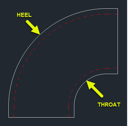
What’s a little less obvious is how to adjust the throat and heel lengths on a radius elbow. If the liner is developed based on metal size, the throat is typically too short and the heel a little long. This is due to the bending allowance of thicker materials. While acoustic liner has a little give but when using something like armorflex for liner, it’s a little more rigid and these lengths can cause issues.
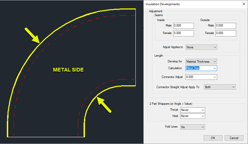
To better understand the Throat and Heel of a radius elbow, we can look at the Top view (cheek). The following image shows the Throat and Heel pointed to with arrows. You’re looking at these parts on their edge.
Prepare Your Fittings
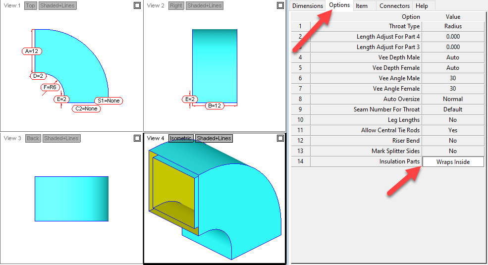
To configure the calculation used for the liner on these parts, you first need to change an option on your ITM. The following image is for a radius elbow (CID 4). Here you’ll want to change the “Insulation Parts” Option to “Wraps Inside“. If you leave this set to the default “Same”, the adjustments made later will have no effect.
Configure Material Adjustments
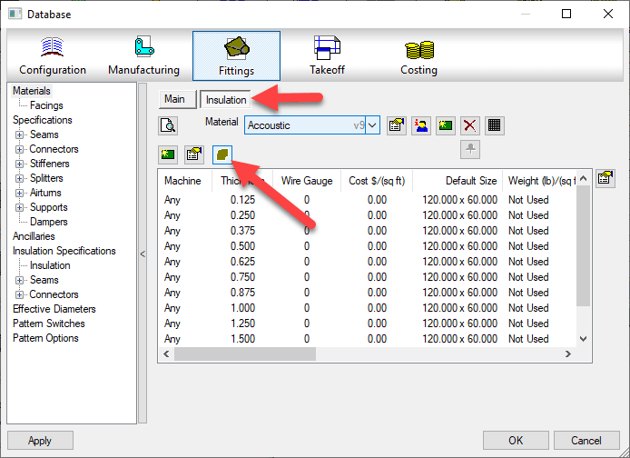
To make adjustments to the liner calculation, you’ll go to the Insulation Materials and click the “Insulation Developments” button.
This will bring up a dialog where you can make changes to how the liner gets developed on the throats and heels. The various settings are as follows…
Metal Side
Throat & Heel Liner Developed to the same length as the metal fitting.
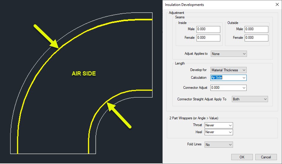
Air Side
Throat & Heel Lengths Developed Based on the AIR side of the liner thickness.
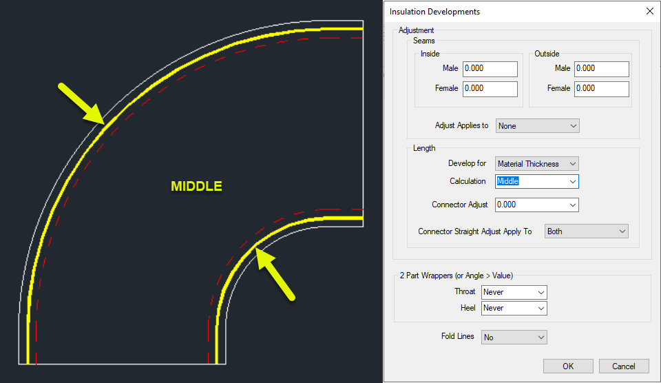
Middle
Throat & Heel length developed based on the middle of the liner thickness.
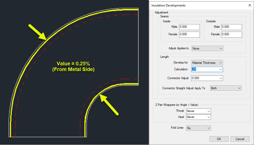
Value (Between 0.0 and 1.0)
Value is between 0 and 1 as a percentage of the liner thickness calculated from the metal side.
0 = Same as “Metal Side” 0.5 = Same as “Middle” 1.0 = Same as “Air Side”
Not All Fittings Supported
Not all fittings support the “Insulation Parts” option. You can run one of the Library export scripts that dumps all the OPTIONS to a CSV file and sort in Excel to look for the CID’s in your library that support “Insulation Parts”. Scripts can be found here.
If you use network licenses or create network deployments of CADmep, CAMduct or ESTmep you may encounter errors. Autodesk incorrectly pathed the Network License Manager files in the SETUP.INI files.
Even if you are using Stand Alone or User Based Subscription licenses but build Network Deployments, if you configure the deployment to include all components in the deployment (recommended if you plan on modifying the deployment later) you can encounter errors.
To correct the errors, you can replace the SETUP.INI files that are part of the installation with the ones provided in the following ZIP file…
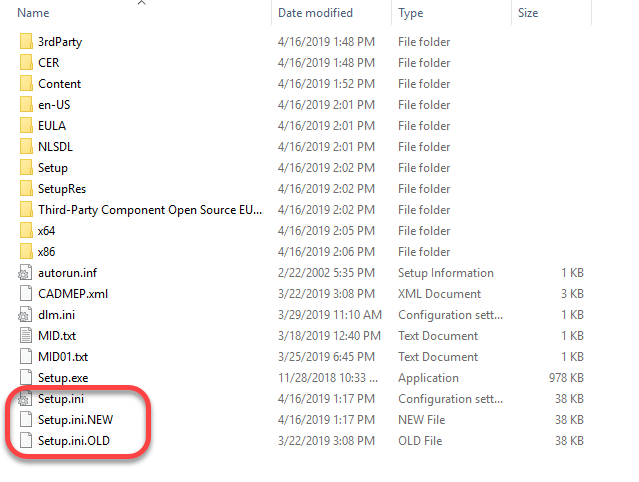
Before you overwrite your installation’s SETUP.INI file, it’s a good idea to backup the original. The root of my installation folder looks like this…
At some point, I would expect Autodesk will update their download data and provide the proper files. Because of this, I would highly recommend NOT replacing the SETUP.INI files unless you encounter issues.
What’s Different?
If you’re curious what’s different between the two, you can open the INI files in Notepad or other text editor and view them there.
The original file contains this at the end of one of the entries…
Third-Party Component Open Source EULAs:x64\en-US\Tools\NLM.msi
The new SETUP.INI files have updated it to this…
Third-Party Component Open Source EULAs:x86\AdskLicensing\NLM\x64\NLM.msi
Here’s another simple Attacher tip for Fabrication products. If you hold down the Shift key while clicking on the Attacher arrow in CADmep, ESTmep or CAMduct,. the arrow rotates the opposite direction.
Clickingthe Attacher – Notice it Rotates in the “Clockwise” Direction Clickingthe Attacher – Notice it Rotates in the “Counter-Clockwise” Direction
Sometimes the best tips are the simplest. They can often be forgotten about or never learned because of that. Here’s a reminder for those that may not know or have forgotten…
In CADmep, or the 3d viewer of ESTmep or CAMduct, you can hold the Control key while clicking the attacher arrow to rotate the arrow 180 degrees. The below screen recordings are both done from CAMduct but ESTmep or CADmep work just the same.
Clickingthe Attacher – Notice it Rotates in 90-Degree IncrementsCtrl-Clicking the Attacher – Notice it Rotates in 180-Degree Increments
Over the years, I’ve written a number of scripts helpful for managing an Autodesk Fabrication configuration. I’ve given them away in my Autodesk University session I’ve taught so they’ve circulated around a bit.
I’ve rewritten most, streamlined them, made enhancements, added others, etc, etc. Because I’m always updating and changing them, I thought I’d host them here too. I can then just post when I update them.
There’s are 2 sets of scripts covering the following topics…
Debugging Properties Scripts
Job Item Scripts
Library Item Scripts
One set is for use in 2019.0 and earlier versions (but work in any version), the others are designed for 2019.1 and later when Autodesk added support for the Pattern Number property.
You can get to the scripts from the menu or click here. The scripts are free to use for all except employees of ENGworks or anyone working on the behalf of ENGworks. (contractors, consultants, etc.) who are prohibited from use.
When you build content, it’s often desirable to have certain dimensions or options locked. This even applies to connectors, seams and dampers but to a lesser degree.
If you have a lot of Dimensions and/or Options to Lock or Unlock, you don’t have to individually pick each one. You can lock or unlock many very quickly provided they’re in a row.
The trick is simple….pick the button to lock/unlock the first field you want to change, and then while still holding the pick button drag your mouse up or down. This is a fast an efficient way to lock large groups of properties without picking each one.
The following recording shows this process. We’re using Pattern Number (CID) 910 as our example.