If you’d like to move you AutoCAD workflow to BIM360, you can now easily accomplish this. It’s really quite simple and requires a couple things….
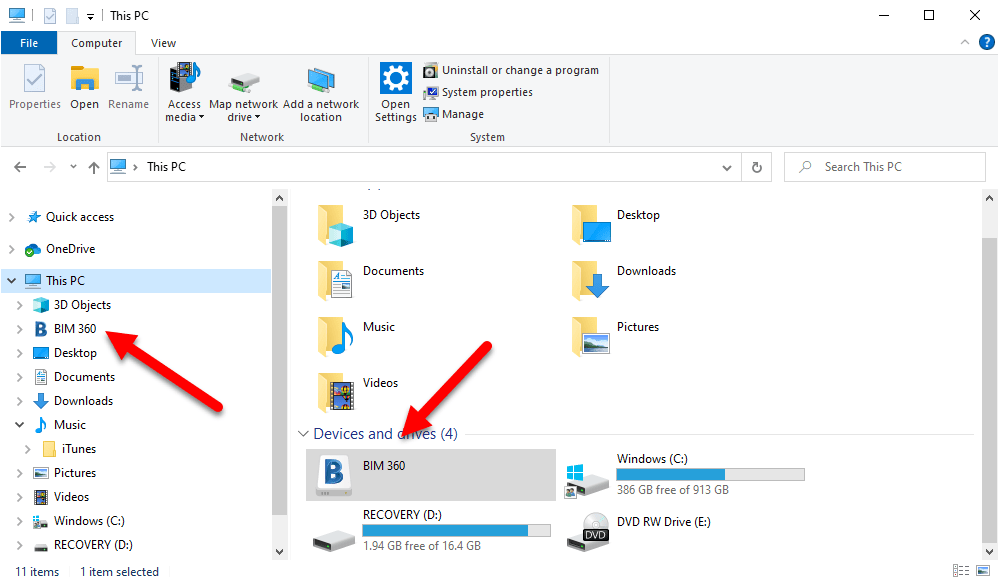
First, you nee to install the Autodesk Desktop Connector. This adds a BIM360 “Drive” to your computer much like OneDrive, Google Drive, Dropbox, etc. This BIM360 drive provides access to your BIM360 Projects that you’ve been granted access to from your BIM360 Administrator.
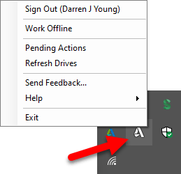
Once the Autodesk Desktop Connector is installed, you can access your BIM360 projects from this drive. You may need to login first to see your projects. You can do this by right-clicking on icon in the System Tray.
You can get the Autodesk Desktop Connector using this link.
Second, there’s a new utility called File Locking for Autodesk BIM360. This utility allows AutoCAD to “lock” the drawings you open on BIM360 so that no others can edit them at the same time.
You can download and install the File Locking for Autodesk BIM360 from the Autodesk App Store using this link.
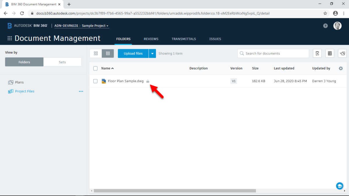
When you now open a DWG from the BIM360 drive, BIM360 will lock the DWG and prevent others from editing it at the same time.
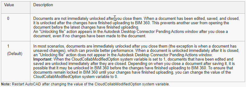
A final word….Once the File Locking utility is loaded, you can use the CloudCollabModifiedOption system variable to control how file locking is handled when you close the DWG in AutoCAD. Details here…
The following is an overview of the changes made to the AutoCAD 2020 release.
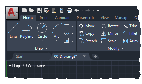
New Dark Theme
Improvements to the clarity and crispness of the dark theme. Similar sharpening was also applied to the light theme as well.
Background colors were optimized the with the icon colors to provide the optimum contrast without distracting from the workspace, where the focus should be.
Ribbon Access
Application button > Options > Display tab > Window Elements > Color Scheme
New Commands
None.
New System Variables
None.
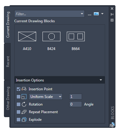
Blocks Palette
Redesigning the Insert dialog box was to provide better visual previews of blocks in the workflow for inserting blocks. The palette increases efficiency for finding and inserting multiple blocks-including the new Repeat Placement option, which can save you a step in some cases.
Key features in the new blocks palette facilitate your specifying and inserting blocks efficiently from a most recently used list or from specified drawings. Three tabs are available to provide the following:
The Current Drawing tab displays all the block definitions in the current drawing either as icons or as a list.
The Recent Blocks tab displays all the most recently inserted blocks either as icons or a list regardless of the current drawing. These persist between drawings and sessions. You can remove a block from this tab by right clicking it and choosing Remove from Recent List.
The Other Drawing tab provides a way of navigating to folders from which you can choose drawings either to insert as blocks or to choose from the blocks defined in those drawings. These drawings and blocks also persist between drawings and sessions.
The top of the palette includes several controls, including a field for applying wildcard filters to the block names, and several options for different thumbnail sizes and list styles.
Ribbon Access
Home tab > Block panel > Insert.
Access from the ribbon provides a gallery of the blocks available in the current drawing together with two new options, Recent Blocks and Blocks from other Drawings.
These two options open the Blocks palette either to the Recent tab or the Other Drawing tab. The gallery displays the same content as the Current Drawing tab.
Placing blocks from the palette can be accomplished by dragging and dropping or clicking and placing.
New and Changed Commands
BLOCKSPALETTE – Opens the Blocks palette.
BLOCKSPALETTECLOSE – Closes the Blocks Palette.
CLASSICINSERT – Opens the classic Insert dialog box.
INSERT – Starts the BLOCKSPALETTE command except in scripts, which open the legacy INSERT command for script compatibility.
-INSERT – Starts the command line version of the classic INSERT command.
New System Variables
BLOCKMRULIST – Controls the number of blocks displayed in the Recent tab of the Blocks palette.
BLOCKNAVIGATE – Controls the file and blocks that are displayed in the Other Drawing tab of the Blocks palette. Valid values include: Path/filename and extension to an existing file, and “.” (None), in which case the last-used file is remembered the next time the palette is opened and persisted across sessions.
BLOCKREDEFINEMODE – Controls whether the “Block- Redefine Block” task dialog box is displayed when inserting a block from the Blocks palette with the same name as a block inside the current drawing. 0= Don’t prompt to redefine-always use the local block definition. 1= Display the “Block – Redefine Block” warning dialog box when appropriate (Default).
BLOCKSTATE (Read only) – Reports whether the Blocks palette is open or closed.
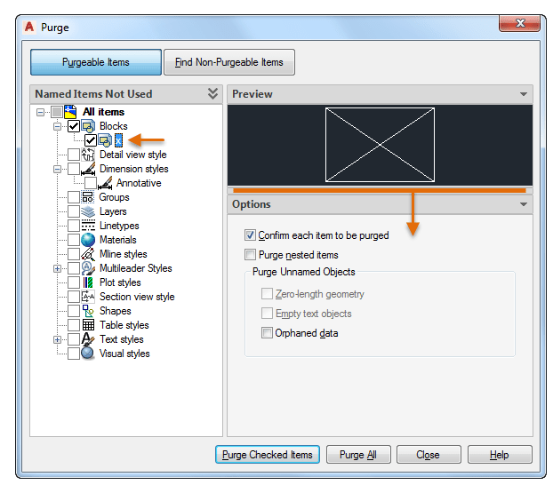
Purge Redesign
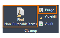
The Purge feature has been revised for easier drawing cleanup and organization. The control options are nearly the same, but the orientation is more efficient and a resizable preview area is now available.
You can now purge zero-length geometry without purging empty text objects.
Check boxes in the Named Items Not Used panel provide a way to select purgeable items by category as well as individual items.
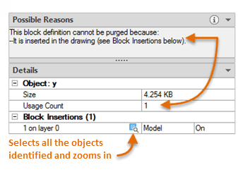
With one click, the Find Non-Purgeable Items button displays additional information specific to why the checked item cannot be purged, which will be helpful in many cases.
For objects that can’t be purged, the new design provides enhanced information as shown below, including the number of objects on which layers, and their impact on file size. The Select Objects button in the illustration below, zooms in on the specified objects that can’t be purged.
These options control whether Purgeable Items or Find Non-Purgeable Items is currently displayed in the Purge dialog box.
New Commands
None.
New System Variables
None.
DWG Compare Enhancements
The primary enhancement to the DWG Compare feature is that you can now directly compare and edit the current drawing together with a specified drawing while in the compare state. The changes you make in the current drawing are closely tied to the compared drawing and changes between the drawings are dynamically compared and highlighted.
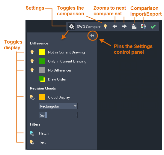
To facilitate direct editing in the compare state, the COMPARE command was moved from the ribbon to a docked toolbar at the top of the drawing area. Most of the options were combined into the Settings control and enhanced as shown. You can easily toggle the comparison from the toolbar and the display of the types of differences from the Settings control.
Also, the default colors can easily be changed by clicking on a color, red to yellow in this illustration, for your preferences or for colorblind-friendly colors.
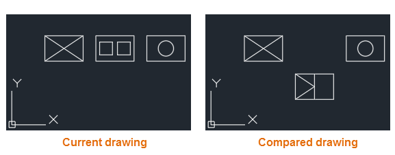
For example, let’s say you need to compare the differences between two highly complex drawings that have been simplified to look like the following:
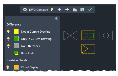
The result of comparing the current drawing with the compared drawing looks like this:
The change sets are each surrounded by orange revision clouds, which are more clearly visible when you’re zoomed in.
You can import the highlighted differences (yellow) from the compared drawing into the current drawing. If you do so, these objects will now exist in both drawings and will automatically turn gray. Only the objects in the specified area that are not in the current drawing can be imported.
You can also export both drawings into a new “snapshot drawing” that combines the similarities and changes between both drawings. The result of this operation is the same as a drawing comparison in AutoCAD 2019.
The arrow buttons provide a way to step through each change set, automatically zooming in to each successive or previous change set.
Ribbon Access
Collaborate tab > Compare panel > DWG Compare.
New Commands
COMPARECLOSE – Closes the Compare toolbar and exits the comparison.
COMPAREEXPORT – Exports the comparison results into a new drawing, called a snapshot drawing, and opens the drawing.
COMPAREIMPORT – Imports objects from the compared file into the current drawing. Only the selected objects that exist in the compared file and not in the current file are imported.
New System Variables
None.
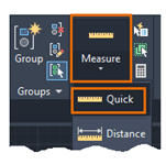
Measure Geometry Option-Quick Measure
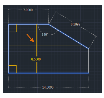
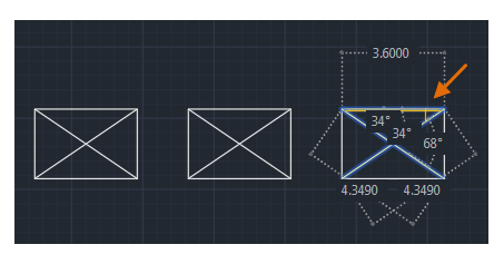
Measuring has become much faster with the new Quick option of the MEASUREGEOM command. With this option, you can quickly review the dimensions, distances, and angles within a 2D drawing.
When this option is active, the cursor displays all nearby measurements, both inside and outside the nearest parts of a drawing. The squares displayed at the left side of the illustration represent 90 degree angles.
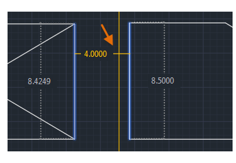
The distance between the two objects is measured in the illustration below because they’re parallel.
Tip: To avoid quick dimension clutter and to improve performance, it’s best to zoom into complicated areas.
Ribbon Access
Home tab > Utilities panel > Measure/Quick.
Changed Commands
MEASUREGEOM – Adds the Quick option for real-time measurements.
New System Variables
None.
Save to Web & Mobile Enhancements
AutoCAD 2020 includes additional support for AutoCAD Web and AutoCAD Mobile. The enhancements are as follows:
Support cloud connectivity and storage. Depending on what you have installed, the Places list in AutoCAD file selection dialog boxes can include Box, Dropbox, and several similar services.
Xrefs are now included with the drawing files that you save for web and mobile access.
The CAD Manager Control Utility includes a new checkbox on the Online Content tab to disable the SAVETOWEBMOBILE and OPENWEBMOBILE commands. This control has been added for sites that require their drawings to remain within their organization’s network.
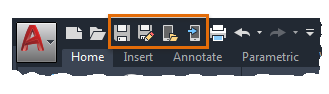
Access
Quick Access toolbar save and open commands:
New Commands
None.
New System Variables
None.
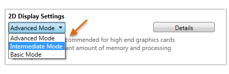
Graphics Configuration
AutoCAD now launches correctly with different DirectX drivers (Dx9, Dx11, or no driver), high resolution (4K) monitors, and dual monitors. In addition, the graphics display settings are consolidated into three modes, which includes gradient hatches and images. The graphics performance setting, Intermediate Mode, is updated to reset several display parameters automatically to optimize your display.
Access
Enter GRAPHICSCONFIG at the Command prompt.
The Graphics Performance dialog box displays, shown in part below.
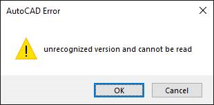
If AutoCAD has ever given you an error “unrecognized version and cannot be read” error, it’s likely a corrupt CTB/STB file. An image of the error can be seen below…
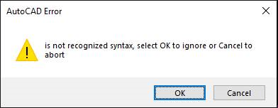
You can also see this followed by another error dialog, “is not recognized syntax, select OK to ignore or Cancel to abort“. This error also shown below, is likely related to the same corrupt CTB/STB file.
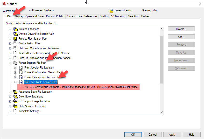
Where Are CTB/STB Files Located?
To find where your plot style tables are located, type “OPTIONS” in AutoCAD”s command line. In the “FILES” tab, expand the “PRINTER SUPPORT FILE PATH” node as shown below.
A few things to note and the plot style tables support path….
Support paths are specific to the AutoCAD profile that’s loaded. Load a different AutoCAD profile and the path may be different.
AutoCAD profiles are user specific, if other users log into the system, they may also be pointed to a different path.
Support paths for the plot style tables will follow nested folders. That is, if you have folders under the configured path, AutoCAD will look in all those sub-folders for additional CTB/STB files too.
Shortcuts are followed. IF you have shortcut placed in the support path, AutoCAD will also follow and look for CTB/STB files in the location the shortcut points to as well as any sub folders there too.
ActiveX is a framework developed by Microsoft in 1996 which adapts earlier concepts of COM (Component Object Model) and OLE (Object Linking and Embedding). Most people may think of this as Visual Basic (pre .Net era) programming.
This was supposed to fade away as Microsoft moved to the .Net based languages so Autodesk pulled support in the shipping versions of AutoCAD years ago. It was however still available as a separate download for a limited time but that time never arrived. Microsoft kept it around and still today, Autodesk supports VBA, a version of Visual Basic embedded within the Application over half a decade later.
If you’e not interested in programming AutoCAD in VB or VBA but do use AutoLISP, I’d encourage you to keep reading, this article is still for you.
Enabling VBA in AutoCAD
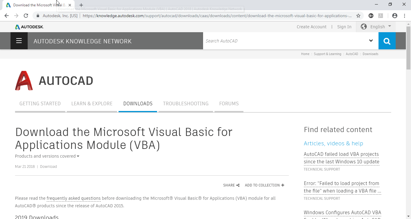
If you want to take a stab at VBA programming in AutoCAD, you’ll need to install the Visual Basic Extension. The extension can be downloaded for 2016 – 2019 versions of AutoCAD from this link….https://tinyurl.com/AcadVBAInstaller
Download the VBA Enabler for AutoCAD from Autodesk’s web site.
VBA Help for the AutoLISP Programmer
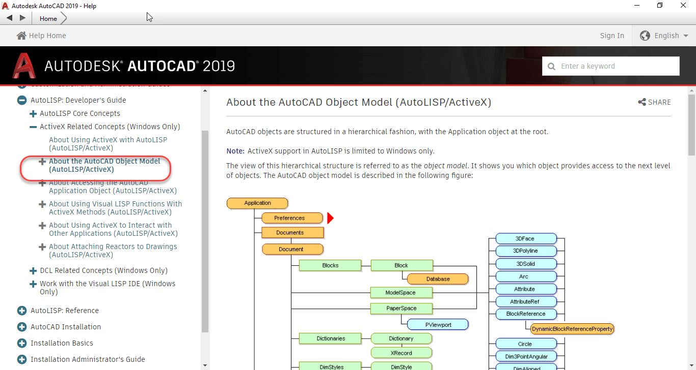
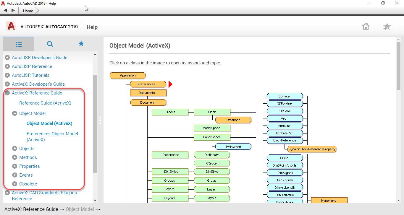
Now, with AutoCAD’s help now Online, you might be tempted to think that it’s the most robust help you can get from Autodesk. Simply typing “F1” will bring up AutoCAD’s help and browsing through the developer documentation, you can find documentation of AutoCAD’s ActiveX Object Model like seen in the following image.
AutoCAD’s ActiveX Object Model is buried in the AutoLISP documentation Online.
Looking at the above image, the graphic of the Object Model contains no hyperlinks. And there’s no documentation on the Methods, Properties and Events typically available for this type of programming.
If you’re programming in VBA, the VBA Editor has tools for helping navigate this model or provides a lot of Auto Complete functionality when typing code. This doesn’t help anyone trying to program ActiveX from AutoLISP.
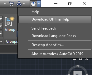
This is where the Offline Help comes in. You can access the OffLine Help download page from within AutoCAD by clicking the down arrow next to the question mark in the upper right corner of AutoCAD and then selecting Download Offline Help to download and install the help system.
Got to the Offline Help Download page from this menu.
You can also click the following link….https://tinyurl.com/Acad2019-OfflineHelp to go to the AutoCAD 2019 Offline Help download page as shown in the following image.
Download and Install Offline Help from this page.
Configuring Offline Help
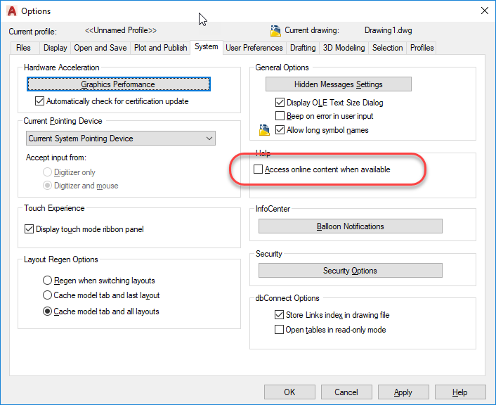
Once installed, you can configure AutoCAD to use the Offline version of Help by typing Options at the command line and clearing the toggle in the following image.
Clear this Toggle to Default AutoCAD to Offline Help
Once configured, typing “F1” will access the Offline help. One of several added pieces of Documentation which includes the ActiveX Developer’s Guide, is the ActiveX Reference Guide. You can see the graphic of the same Object Model documentation as before, but this one is hyperlinked to documentation of the Objects as well as lists all of the Methods, Properties and Events.
The ActiveX Reference Guide contain all the documentation you need for ActiveX programming.
While all of documentation is written with the Visual Basic programmer in mind, the organization of the ActiveX object model and everything else is where you can get all the documentation you need to help translate the function calls to their AutoLISP syntax. When you make a call to (vl-load-com) in AutoLISP, you have access to over 2000 additional AutoLISP functions with a VLR- prefix. These functions are all documented here in the ActiveX Reference Guide in Visual Basic syntax.
In a future post, I’ll explain how to translate the Visual Basic documentation to AutoLISP syntax. If you don’t want to wait, review the ActiveX documentation found in the AutoLISP developer guides…it’s all in there!
One Final Note: You do NOT need to install the VBA Extensions in order to program w/ActiveX from AutoLISP. Just install with Offline Help and you’ll have everything you need.
If you’re an AutoLISP programmer and use Autodesk Fabrication CADmep, you most likely know that there’s a COD Scripting language in Autodesk Fabrication that provides read and/or write access to CADmep properties. The problem with COD Scripts, is that sometimes they’re not powerful enough to do all of the other things you’d like to do and you may want to use AutoLISP.
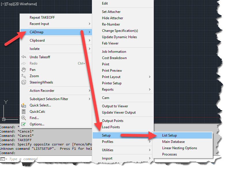
What you may not know is that you can access the vast majority of CADmep properties from AutoLISP. To so this, you need to configure CADmep’s List Setup dialog which will provide a light weight but similar interface to what you see when you build reports in Autodesk Fabrication.
To access List Setup, right-click in an open area or the drawing editor and then select “CADmep” -> “Setup” -> “List Setup” from the menu.
ListSetup will Provide access to CADmep Properties
Configuring List Setup will provide access to the configured properties via DXF codes which are one of the most common ways of accessing object properties in AutoLISP. (You can also access these same DXF based properties via VBA, ARX or .Net)
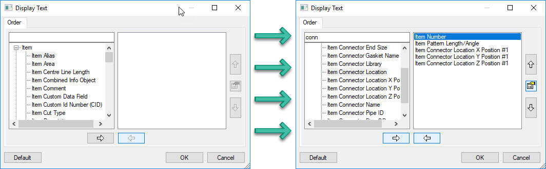
The following image shows the List Setup dialog before (left) and after (right) being configured. Simply add the properties you want to extract in the order you want them.
Before and After Configuration of List Setup
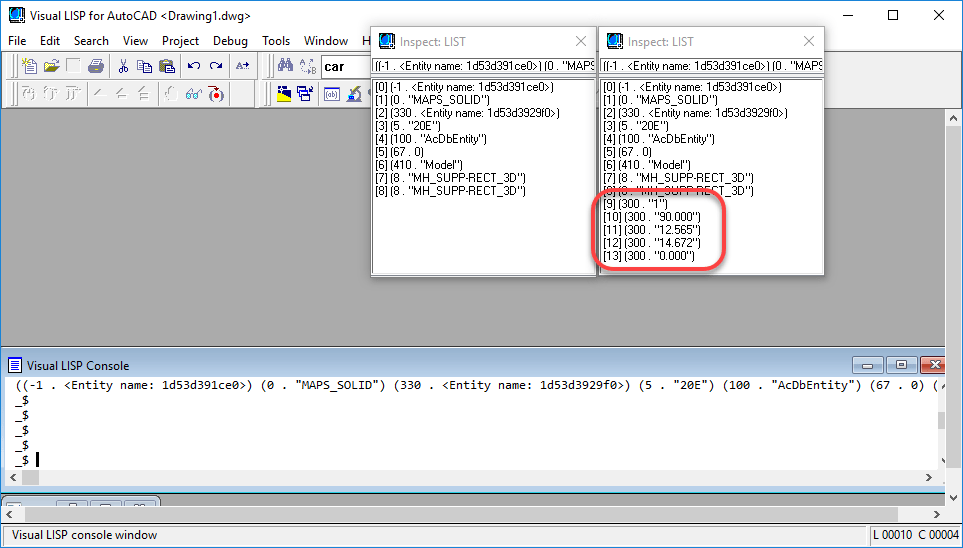
Once you’ve configured the properties you want, a simple call to the (ENTGET) function in AutoLISP will return the data you’re looking for. You can see in the following image, that we’ve saved the DXF data to two different variables in the VisualLISP editor. The listsetup-blank variable (left) was done before configuration and the listsetup-config variable (right) was done after the configuration of List Setup.
CADmep Properties can be Found in the 300 DXF Group Codes
The code used to extract the data is the following….
Because the VisualLISP editor does not word wrap it’s results, you can use the Inspect
Now, there are a few things to know about this method….
All CADmep properties show up in DXF Group Code 300. If you are returning multiple properties, you’ll have multiple 300 codes to parse through.
The order the properties are configured in List Setup is the order the properties will appear when returned in AutoLISP. There really is no other foolproof way of knowing which codes are which properties (unless obvious by their value) without knowing the order List Setup was configured.
If you later change the properties or their order, you’ll likely break your existing code. Think carefully about what you may want later and add it from the start even if you don’t want it at this time. If you need to add properties later, simply add them to the end of the list.
This method works well for reading Fabrication properties. It doesn’t allow you to set them using functions like “(ENTMOD)” or “(ENTUPD)“
Have you ever received a list of coordinates in a CSV file and wanted to place those in AutoCAD? Were you aware this can take as little as 2 minutes?
For a very long time, AutoCAD has supported SCRIPT files. A script file is nothing more than a text file (using only Notepad) that lists the everything that you’d typically type to AutoCAD’s command line.
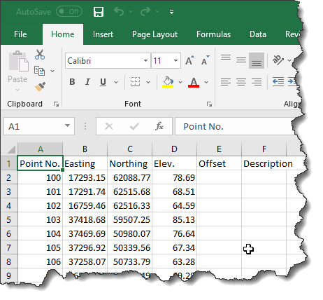
Take for example the following CSV file. How would we get this into AutoCAD?
Points List in CSVFormat Opened in Excel
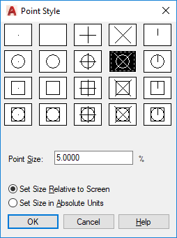
To figure out what we need to type in AutoCAD, let’s first start by making sure our Point style is something other than a single dot so it’s more easily visible on your screen. To do this, type “PTYPE” at AutoCAD’s command line. If you don’t get the following dialog, Escape out of the command and type “DDPTYPE” and try again. Select a point style that suites you.
Point Style Dialog
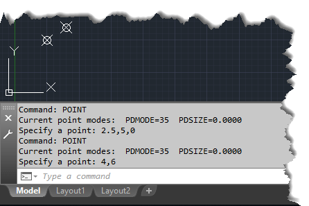
Now that you have a point style that’s more visible on the screen, lets type the Point command and see what input it takes.
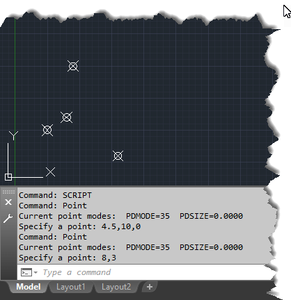
You can see from the below image of the command line that once we type “POINT” and press ENTER or SPACEBAR, there’s a little text that displays the current point style and size. You’re then prompted for the coordinates. The points in this example were entered by typing X,Y,Z coordinates for one point and X,Y coordinates for the other. After typing the coordinates and pressing ENTER, the command completes.
X,Y or X,Y,Z Formats Can Be Used For Points
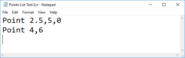
To test this theory, we can use Notepad to manually create a Script file. Type the contents you in the below image and name your file with an “SCR” File extension. You’ll want to make sure Notepad’s “Save as type” drop down list is set to “All Files (*.*)” or else Notepad will append a TXT to the end of the file.
One other thing to also note is that the cursor is after the last line, just below it. This is because there’s an “Enter” after the last point…this is just like hitting Enter on the keyboard to complete a command in AutoCAD.
Use Notepad to Create a Script File
After you’ve created your text file, type the “SCRIPT” command at AutoCAD’s command line and select the Script file you just created. When complete, AutoCAD should have added 2 more points to the drawing.
The Script File’s Input Looks The Same As Manually Typing.
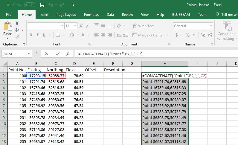
So, now you know how the basis for a script file (same as you’d type manually) and how to create one (using Notepad), the next thing you need to do is convert the CSV file in Excel to a Script file. That’s actually quite simple.
You’ll use Excel’s “CONCATENATE” function which takes several pieces of text and puts them together. In this example, this is the formula we’re using…
=CONCATENATE("Point ",B2,",",C2)
The first piece of text is the Point command. Remember, we can use the SPACEBAR after a command and it’s the same as if we’re pressing the ENTER key. That’s why you see the space after the “POINT“. Each piece of typed text is also contained in double quotes.
=CONCATENATE("Point "
Each piece of text that is concatenated is separated by a comma. After the command, you start typing the X-Coordinate which is the Easting column in the CSV file. Because we’re not explicitly typing text, we can simply use a cell reference like so…
=CONCATENATE("Point ",B2
When typing coordinates in AutoCAD, we separate them with a comma, so we use another comma for Excel’s Concatenate function, then a comma explicitly typed in double quotes.
=CONCATENATE("Point ",B2,","
Finally, we add the Y-Coordinate which is in the Northing column using a cell reference, again, remembering to separate all the pieces of data with a comma and close the Excel function with a closing parenthesis.
=CONCATENATE("Point ",B2,",",C2)
When you’re done, copy the formula to the other cells. You can see in the image, that we have a line of text similar to what we typed in Notepad manually the first time. The below image, I’ve used the F2 key to edit the first cell so you can see the formula and the cell references.
Excel Used to Build a Script File
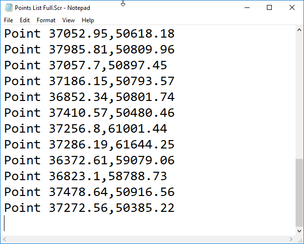
Now that you’re text in Excel is in a Script File format, you can guess the next step. Copy/Paste the text into Notepad, Save with a TXT extension on the file name.
Make Sure the Cursor is on the Last/Empty Line
The last step is to run the script file in AutoCAD using the Script command. Zoom Extents in AutoCAD to see your points. The CVS file, Excel File and Script files can be downloaded for examination from this link.
Here’s a screen recording of making and running the script file. As you can see, it takes a CSV file, gets converted into a Script file and places the points in AutoCAD in less than 2 minutes.
CSV Points List to AutoCAD Points in Less Than 2 Minutes
Script files are quite easy. You could easily add more text, and use different commands to do the same thing like Insert an attributed block into the drawing and use the point number as the attribute value. You just need to make sure all your system variables are set to prompt you upon insertion for the attribute value.
The only real downside to Script files is they’re not intelligent. They don’t like extra characters or spaces, the don’t work well with commands that prompt for user input or display dialog boxes and they don’t perform conditional logic to do different things depending what they find. They will however call AutoLISP routines so when I have more advanced work I want to do in a script file, I just have the Script call and run my Lisp as well.
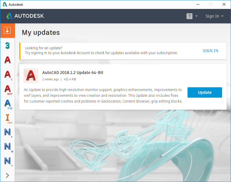
In case you missed it, Autodesk released update 2018.1.2 for AutoCAD a couple weeks ago. Click here to see a listing of the issues fixed in this and previous updates for AutoCAD 2018,
To download and install the update, refresh your Autodesk Desktop App and updates should appear if you have an active subscription (maintenance plan or annual subscription). The Autodesk Desktop App icon is located in your Windows System Tray if it was installed.
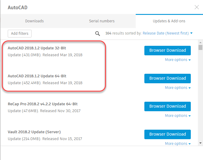
You can also access them from the Product Downloads section of the Autodesk Accounts portal if you are a contract manager or software coordinator in your account.
A Fabrication Database that’s well managed should have changes being made. This can mean things like materials, specifications, services, connectors and such may be occasionally deleted and removed. If there are proxy items in your database that have {brackets} around them, they should be made permanent or removed as well.
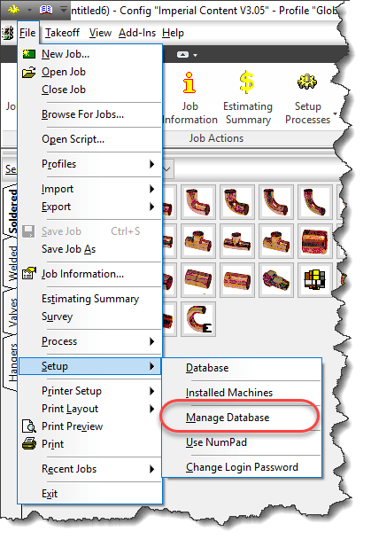
The way to do this is to PURGE and/or COMPACT your database, You can do this by typing PURGEDB on AutoCAD’s command line or by selecting File -> Setup -> Manage Database from ESTmep or CAMduct as sown in the following image.
When you initiate this process, you’ll be presented with a standard “Backup Your Database…” warning which you can click OK to.
From there, you are then presented with the following dialog.
Items that show up here are the ones that show up with {Brackets} in your database, They should either be made permanent or removed in a well managed system.
The Make Permanent option is fairly safe. The items are in your database already there and already have indexes assigned.
On the other hand, the Purge Database option will remove them from your database. When you do this, the’s a chance that some of the database indexes will change as those indexes are how the various database tables relate to each other.
If you do this while others are using the database in CADmep, ESTmep or CAMduct, they already have the database tables loaded into memory. Depending what they are doing, some activities may cause parts of the database to be reloaded while others are not. When this happens, strange things can happen to your drawing…your systems might loose their service or change services or connectors change without notice. More times than not, unless you catch it right away,by the time you find the issue you’ll need to remodel your data or retrieve it from a backup.
In a Database, records are not actually deleted so while the Purge command appears to remove items from the database, it actually just flags them as being unused so those areas in the database can be overwritten with new data later. This is where Compacting the database comes into play. The Compact the Database Now option will rewrite and re-sequence all the database files and their indexes to recapture that unused space. Again, this causes issues for others who are currently referencing the database and doing work.
While there is danger in using these commands, they should be used to properly manage your database. The key here is to use them after hours when other users are not using the database. Another option would be to do your development work in a copy of the database so nobody is ever “using” the database you’re performing administration work in. When you’re done, you can “copy” this database to the production database but again, after hours when nobody is doing work or you could have all users log out temporarily (perhaps at lunch) and copy the database then.
To the best of my knowledge, this issue is NOT present for those of you using Revit with Fabrication parts. Revit loads in your services and content and caches it in the Revit model. It doesn’t reference the database configuration again while you work unless you manually “reload” the configuration, So unlike CADmep, ESTmep or CAMduct which may reload parts of your database just by using the software, Revit won’t do this unless you manually reload in which care it will reload everything and keep all those database sequences sin check.
If you’ve ever opened an AutoCAD drawing and your parts appeared orphaned from their services, connectors changed to things that don’t make sense or your Cast Iron NoHub Waste system suddenly reports as Rectangular Supply Air, this likely was the cause and this Best Practice is for you.
AutoCAD does a lot of things for you automatically. Unless you’re an old timer from back in the DOS days, you may not be familiar with all the options you can choose from when presented with the “Select Objects:” prompt in AutoCAD, In days of old, AutoCAD displayed all of the options on the command line when going into selection mode. There were less options back then and a lot of what happens automatically now, you had to type the options for,
Today, there’s a lot more options so AutoCAD no longer displays them unless you type an invalid entry. Even then not all the options are displayed. Many of the options now are default behavior making the options less critical in operating AutoCAD efficiently. None the less, they are often helpful. Here’s a chart of the options available. A description of each option follows. For more detailed information, you can refer to AutoCAD’s Online Help using the following link.
Alias
Option
Modal / Single Use
A
Add
Modal
ALL
Everything
Single Use
AU
Auto
Modal
C
Crossing
Single Use
CP
Crossing Polygon
Single Use
G
Group
Single Use
L
Last
Single Use
M
Multiple
Modal
O
Object
Modal
P
Previous
Single Use
R
Remove
Modal
Si
Single
Modal
SU
Sub-Object
Modal
U
Undo
Single Use
W
Window
Single Use
WP
Window Polygon
Single Use
Add (A) – Default mode for selection in AutoCAD. As you repeatedly pick items, they are ADDED to the selection set you are building. Stays in effect until switching to REMOVE mode.
All (AL) – Single use option that selects ALL objects in your AutoCAD drawing even if not displayed outside the current drawing area. Object on layers that are OFF and/or LOCKED will still be selected. Objects on layers that are FROZEN will not be selected.
Auto (AU) – Default mode for selection in AutoCAD. It’s combination of two other AutoCAD selection modes combined. SINGLE if you pick on an object, it will be selected. If you don’t pick on an object, BOX selection mode will be a CROSSING if the second point is to the left of the first selected point or a WINDOW selection if the second point is to the right.
Crossing (C) – Single use selection mode where you pick two points to form a rectangle. Anything completely within or crossing the rectangle, regardless of the order or direction the points are picked is selected.
Crossing Polygon (CP) – Single use selection mode where you picks a series of points to form a polygon. Any object completely within or crossing the polygon will be selected.
Group (G) – Single use selection mode that allows you to type the name of a group to add the objects in that group to your selection. When specifying the names of unnamed groups, you must include the asterisk (*) prefix in the automatically assigned anonymous name AutoCAD gives it.
Last (L) – Single use selection mode that allows you to select the most recently added object in the drawing that’s visible, in the current drawing space and who’s layer is not off or frozen.
Multiple (M) – Modal selection mode used to selects objects individually without highlighting them for performance when selecting complex objects. When finished selecting objects you don’t want to highlight, press Enter and you’ll be returned to the default AutoCAD selection mode and still in the select objects prompt.
Object (O) – Default selection mode in AutoCAD where you select objects. Use this option to exit the SUBOBJECT selection mode.
Previous (P) – Single use selection that selects everything that was in the previous selection set (assuming the previous selection set wasn’t erased).
Remove (R) – Modal selection mode that cancels the default ADD mode to remove objects from your selection set. Most useful when it’s faster to select everything (ALL) and remove what you don’t want selected than it is to select everything you do want selected.
Single (Si) – In addition to being a single use selection modem, you can only select one object and the select objects prompt is terminated. If you fail to select an object in SINGLE mode, you are switched to BOX mode.
SubObject (SO) – Model selection that allows you to select edges, faces, etc of complex objects. When in SubObject mode, you can no longer select Objects without using the OBJECT option to return to that selection mode.
Undo (U) – Single selection mode that removes the most recently added object (or objects if they were selected as a group) from the selection you’re building. Can be used repeatedly to keep removing object(s) in the reverse order they were added.
Window (W) – Single use selection mode where you pick two points to form a rectangle. Anything completely within the rectangle, regardless of the order or direction the points are picked is selected. Unlike CROSSING, anything that crosses the window will not be selected.
Window Polygon (WP) – Single use selection mode where you picks a series of points to form a polygon. Any object completely within the polygon will be selected. Unlike CROSSING POLYGON, anything that crosses the polygon will not be selected.
One of the powerful features of AutoCAD is the ability for applications to built on top of it. Unfortunately, these applications can often leave remnants of themselves inside your drawings and cause performance issues. One such side effect is the buildup of Registered Applications or RegAppsfor short. These RegApps are left in the drawing’s Symbol table after entities that contained the XDATA (Extended Entity Data) they used are deleted.
While this can affect any user, this can be very common in the AEC industry as collaboration with external parties and trade partners means you’re typically referencing a lot of files from many sources. I’ve seen cases where a drawing with 50,000 RegApps can take 10 minutes to load and after clearing RegApps, takes merely seconds.
What most people don’t realize is that even though “RegApp” is an option with the PURGE command, using PURGE ALL will NOT remove them. You need to call PURGE separately, with only the REGAPP option. Click the following ScreenCast recording link to see a demonstration of this…
The video shows PURGE ALL and doesn’t list that any RegApps were removed. Purge is then called again, and only the REGAPP option is used which then removes several RegApps. Try it yourself, the drawing used was in the Sample Civil Sheet Set drawings that shipped with AutoCAD 2018.
Problem Keeps Returning?
External References (XREFS) and/or blocks can make the problem difficult to eliminate. You may need to process all Xrefs and block libraries to verify these RegApps aren’t being introduced from those sources. If you’ve used WBLOCK to save a block to disk from a RegApp corrupt drawing, that DWG file also has the issue.
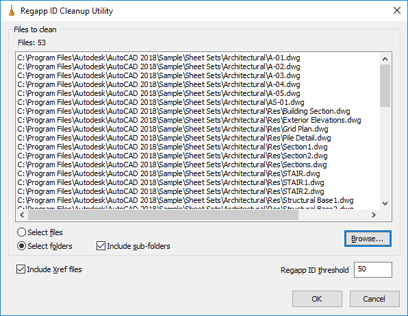
Luckily, Autodesk has a batch utility (free) that will process multiple file/folders, automatically look in sub-folders as well as automatically load any referenced drawings as well.
Click the following ScreenCast link to see the process in action…
One last benefit if this utility is that it can be called from a DOS window with command like syntax. In a collaborative environment where Xrefs are being updated frequently by others, RegApps can keep getting reintroduced requiring this process to be run frequently. Because you can call this process completely automated from the a DOS prompt, this means you can create a batch file that’s scheduled to be run on a regular basis, even nightly on your drawing library. The following Screen Cast link shows how to call the utility from a DOS command prompt…