Do you know what ‘Connector Matching’ is as it relates to Autodesk Fabrication? It’s been in the product since the 2020 release. Yet most people I run into have no clue what it is.
There’s a good reason for that. It’s hidden from view. That is to say, there’s a good reason you don’ know about it. There’s no good reason it’s hidden from you besides Autodesk is pretty slopping (lazy?) when it comes to product design in recent years.
What is Connector Matching?
Connector Matching only works in Revit w/Fabrication Parts. If you’re not using Revit, you need not worry about it but setting it up won’t cause any issues either. It’s designed to place a matching connector on pipe after you cut in a fitting when modeling in Revit. CADmep, ESTmep and CAMduct will simply ignore the settings.
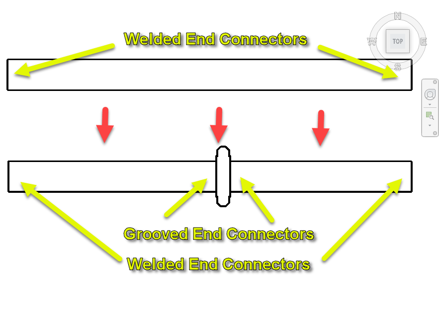
As an example, if you’re drawing a welded piping system and want to break it with a Grooved coupling, Connector Matching places the proper grooved connector on the end of the pipe when the Coupling is placed. This helps us build a system with Welded Pipe Spools that’s assembled in the field with Grooved Couplings…a very common activity in mechanical construction.
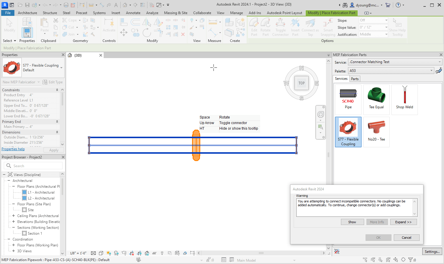
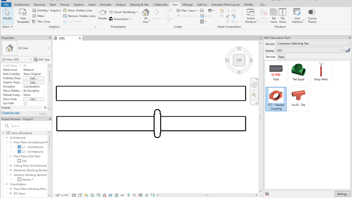
When Connector Matching isn’t configured, you’ll have issues cutting in things like a Grooved Coupling into a Pipe that’s part of a welded system.
Configuring Connector Matching
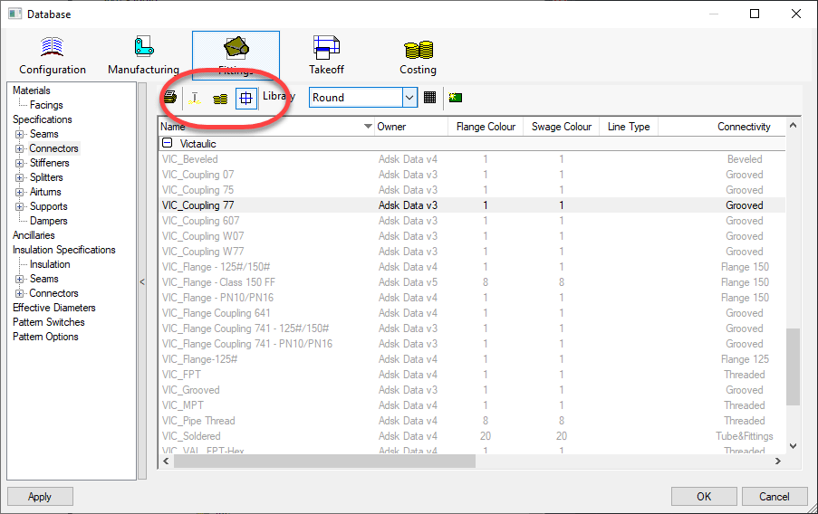
The reason many don’t know about connector matching is because it’s hidden. None of the 3 views (Manufacturing, Costing & Drawing) display this option.
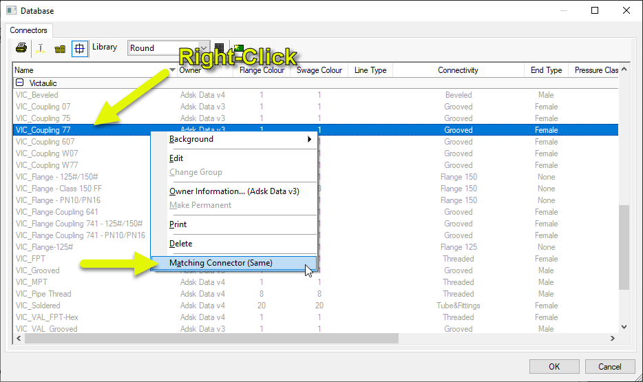
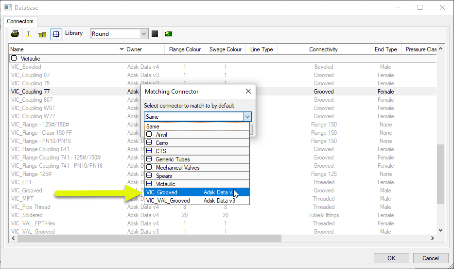
To set Connector Matching, you Right-Click on a connector that’s configured for the Item you need to match. In this case, it’s a Victaulic 77 Coupling.
You can see the Matching Connector is set to “Same” by default. That’s certainly not what we need so select that menu option.
You can see now the Matching Connector is set to a Grooved Connector. So every time an Item with the “VIC_Coupling 77” connector is cut into a piece of pipe, the pipe will get a “VIC_Groove” connector.
Added Configuration to Make it Work
Above, you set the matching connector. Unfortunately, that’s not enough. There’s some added configuration to verify to ensure that it works.
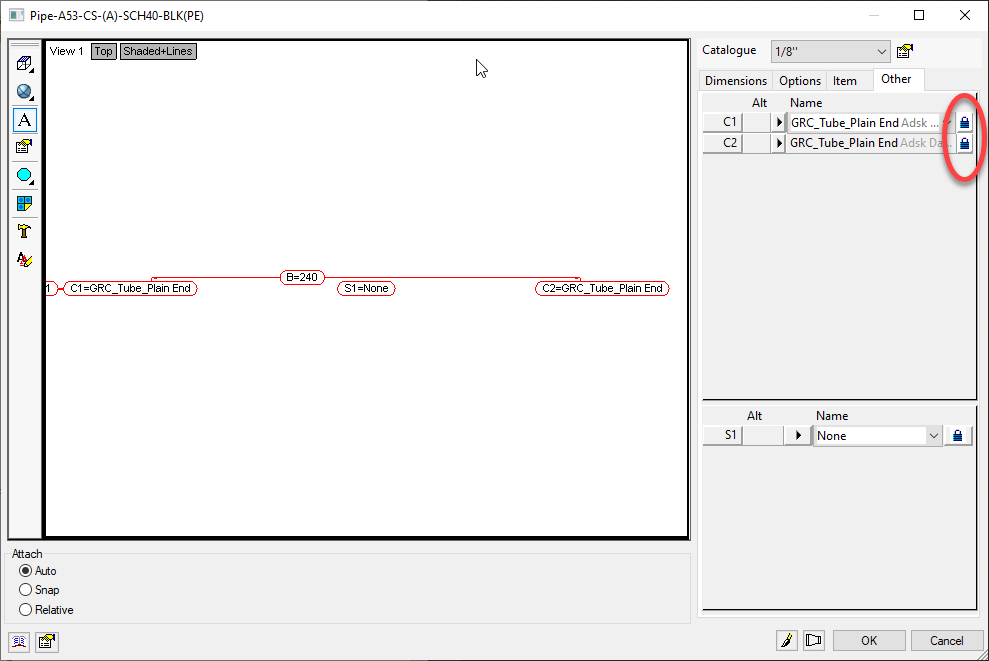
One of the requirements of Connector Matching is to make sure the Pipe’s Connectors are NOT locked and defaulted to the connectors they should use. In other words, ‘Set’ but not ‘Locked’.
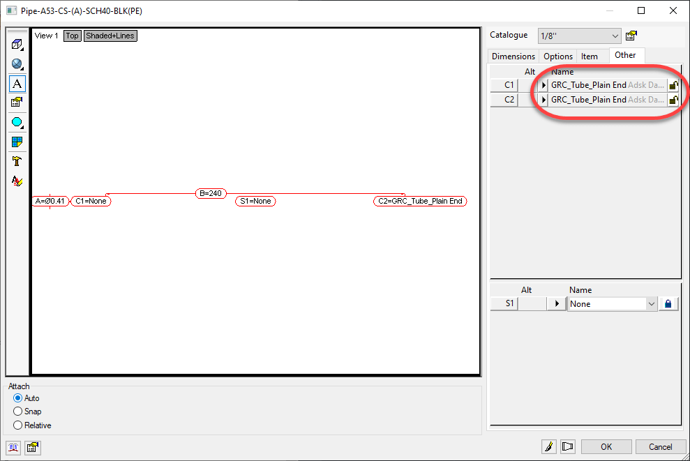
Here’s what your Pipe ITM most likely looks like…
What I recommend here is, Unlocking only 1 of the Connectors and Clicking OK. After you do that, go back and edit the ITM again and take a look at the Connectors.
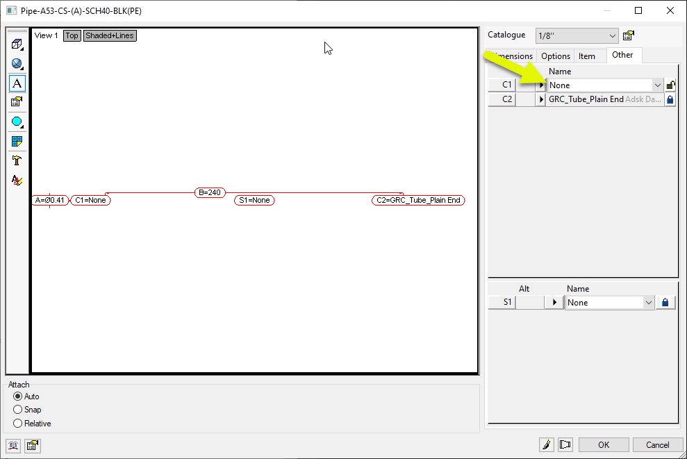
You can see here that after Unlocking one of the Connectors and Clicking OK, going back to edit the ITM the Connector changed to “None”. This is a tell tale sign that there’s yet another thing you have to change to make it work.
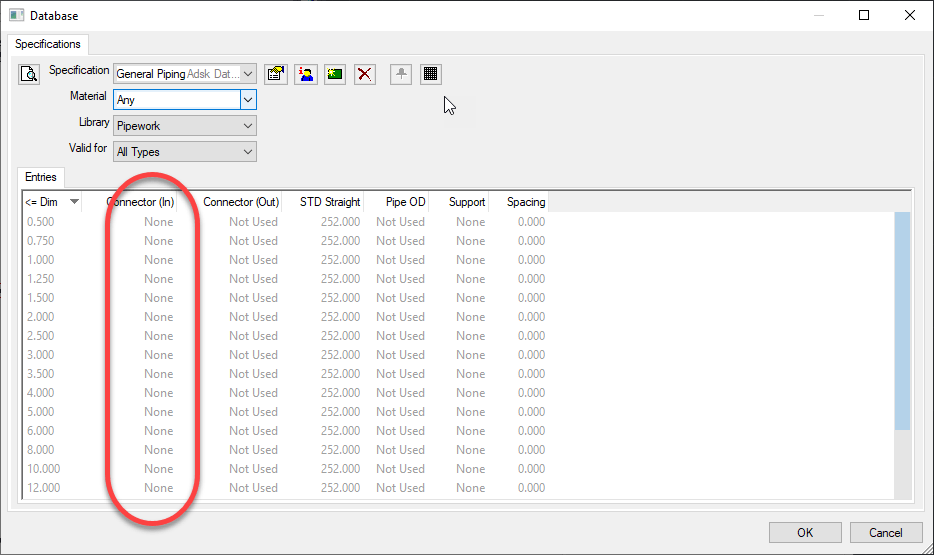
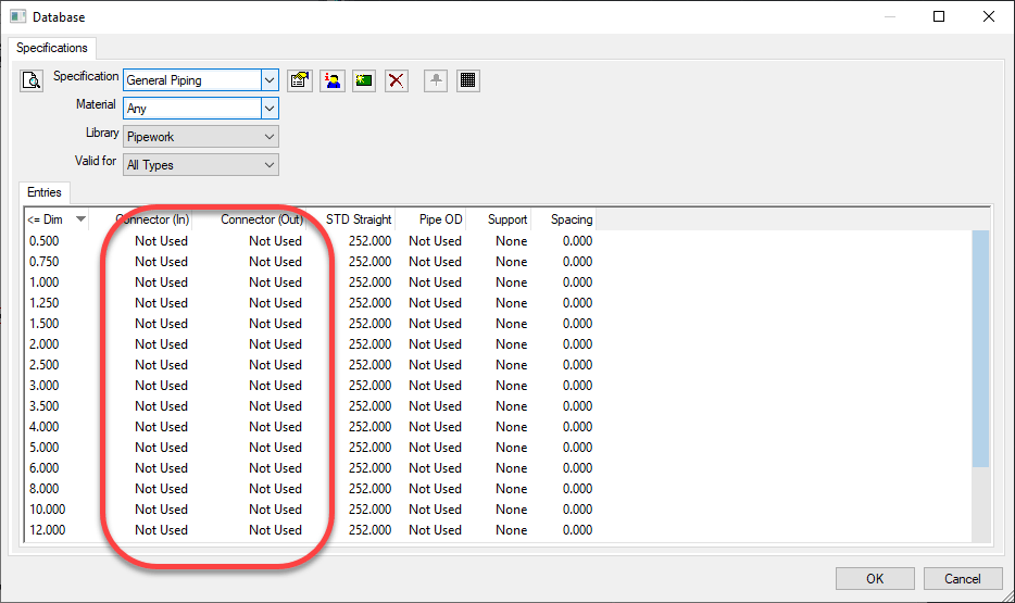
In some Configurations, people have the Specification set to drive the Connectors. This is most commonly done for Sheetmetal but you see it in Piping as well. In the following image, the Piping Specification is configured to set the Connector to “None”.
What we need to do here is set the Connectors in the Breakpoints to “Not Used”. Note, if the Connector you unlocked earlier didn’t change to something other that what it was, you most likely don’t have this issue but still could…it could just be configured to use the Connector the ITM was set to.
You might have to hunt around for which settings apply. It could be on the ‘Any’ material or a specific material the ITM is using. The ‘Valid For’ could have it in ‘All Types’ or ‘Straights Only’. It’s possible too that you don’t have any breakpoints in the Specification at all. If that’s the case, then your Specification is likely already good. But if it’s not, simply ensure the Connectors are all set to “Not Used”.
Once your Specification is setup correctly (if it was a problem in the first place) you can go back to your ITM for the pipe and unlock both connectors but leave them set to the Connector it typically uses.
Once everything is set properly, Revit will then let your Grooved Coupling be placed in the run of pipe.
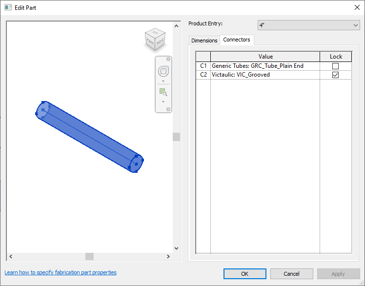
If you Double-Click on one of the pieces of pipe, you can see the Connectors are now set to a Groove for the end where the Coupling is.
A Final Word
Note that these settings were added in 2020. If you’ve had your Database configuration a long time, they’re likely not set. Even Autodesk’s ‘Out of the Box’ configurations that shipped with 2024 don’t have these set. So you’re pretty much on your own to make it work.
If you do ANY Administration of your Database Configuration in 2019 or earlier, these settings will be lost. As I’ve advised many times earlier, pick a version for Administration and stick to it. If you have Admin permissions and use 2019 or earlier, all those settings get lost and because they’re not displayed, you won’t really know.
You can use these settings for all kinds of things. They don’t have to be limited to Grooved Couplings. Changing the end of Steel pipe to Threaded when Cutting in a Threaded Coupling, Threaded Adaptor, Threated Tee, Threaded Valve, etc. All of these things should have their connectors looked at and Matching setup. Just about any of those types of fittings in all materials should have Matching set.
I’ve been seeing a recent trend in project teams. An increasing use of Autodesk Desktop Connector to link Revit Cloud Models. While it can and does work (sometimes), it’s a real bad idea and should be avoided unless absolutely needed. The reasons are subtle and nuanced. But those nuances are a make or break in terms of success.
I’ll try to explain as best I can. I’ll even give you steps you can do to reproduce this issue yourself. But first, let’s go over why Desktop Connector exists in the first place.
A Brief Desktop Connector History
Autodesk’s first attempt at a proper Cloud workflow for Revit was called Collaboration for Revit. It later became BIM360 Design and today is called BIM360 Collaborate Pro. Same idea…take a Revit model and manage it in the Cloud from Sync’d local data. Practically speaking, it’s a cloud version of Revit Server.
Back in those early days, you could link to other Revit cloud models. But Revit supports other types of links besides RVT files. So people would link to file servers. But in a collaborate environment, other teams didn’t have the same file servers or folder structures. Those other linked files linked DWG’s or IFC’s would break. So like the good technologist’s they are, BIM Managers started using services like Dropbox across the product team. Those non-Revit files were linked from there so the links would be common across of team members.
As a result, Autodesk later acknowledged the value in doing this and released it’s own ‘sync’d drive’ tool called Autodesk Desktop Connector. So that’s why it’s there. It’s intended to link non-Revit files or Revit files that are NOT cloud models.
One could argue that Autodesk should have just made Collaboration for Revit work with those other files types. I agree and it’s a nice thought. But it’s likely not the case because the Revit files you see on BIM360 Docs (now Autodesk Docs) are NOT the same files as are used by Revit’s Cloud collaboration tools. You can read more about that here (https://www.darrenjyoung.com/2022/03/29/the-2-sides-of-bim360-acc-docs/)
The False Alure of Desktop Connector
When I see Desktop Connector misused, the reason I’m given is usually the same. “We don’t want to Live Link models“. That’s to say, they don’t want to see daily changes from the other project teams in real time.
So that sounds reasonable. But if people would use BIM Collaborate Pro ‘properly’ this actually solves this problem and in a much more flexible way. BIM Collaborate Pro when setup and used properly allows 3 separate workflows or a combination of any of them….
Link to Live Models
Link to “Shared” copies of Models (only updates when the model owner chooses to share)
Link to “Consumed” copies of Models (only update when you consume a shared copy)
Yup. That’s it. Complete flexibility on how you link to other Revit Cloud Models. In short, if you’re linking to get away from updates you don’t control, it’s because you’re not using the BIM Collaborate Pro properly. More accurately, whoever is hosting the project did not set it up properly and you’re a mere casualty caught in the cross fire. Something most sub-contractors are very familiar with.
The True Appeal of Desktop Connector
There’s really another reason people use Desktop Connector for Revit Cloud models. A result of Autodesk’s flawed logic that everyone on the project should be on the same platform, same project and same account. While it makes sense at a high level, it also means all other project teams who aren’t the hosting company are limited to the willingness and/or capabilities of the hosting company.
Taking that into account, one aspect of Desktop Connector is that you can link ‘between’ BIM360 or ACC (Autodesk Construction Cloud) accounts. That is, you can link files in your account, to project files in another team’s account. This cross account linking is NOT available in BIM Collaborate Pro with Cloud models or Cloud Workshared models but it is in the Desktop Connector.
When you put this all together, this means companies can link to files from other companies but still control their own models on their own account. And they’re not live linked either. This is why we’re seeing a proliferation in Desktop Connector usage with Revit Cloud Models.
The new Autodesk Construction Cloud has some “Bridge” functionality designed to facilitate this. I tested the Bridge functionality when it first came out. It didn’t work as required, expected or as advertised IMO. It may or may not have improved since then but that’s not the point of this article. The point of this article is about linking to Revit Cloud models from Desktop Connector. Why it’s problematic, not a recommended best practice and why it should be avoided.
The Desktop Connector Problem
To demonstrate the problem, we’ll use two separate sets of 3 Revit files each linked to each other within the set like the following…
Set 1(problem set)
Test – 1.rvt(Link to Test – 2.rvt & Test – 3.rvt)
Test – 2.rvt(Link to Test – 1.rvt & Test – 3.rvt)
Test – 3.rvt(Link to Test – 1.rvt & Test – 2.rvt)
Set 2(working set)
Test – A.rvt(Link to Test – B.rvt & Test – C.rvt)
Test – B.rvt(Link to Test – A.rvt & Test – C.rvt)
Test – C.rvt(Link to Test – A.rvt & Test – B.rvt)
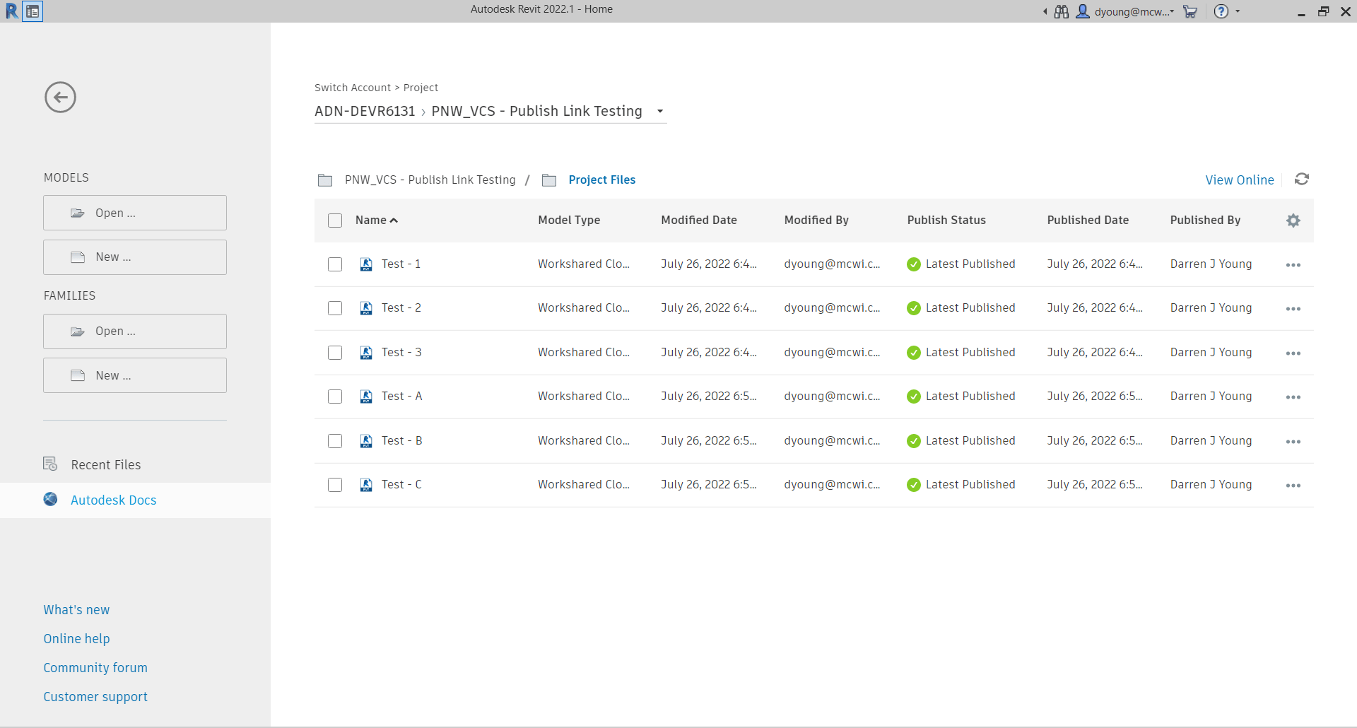
Each Revit model is a Cloud Workshared Model. (a standard Cloud Model would function the same for this issue). You can tell they’re Cloud Models be viewing them in Revit’s interface like shown in the following image…
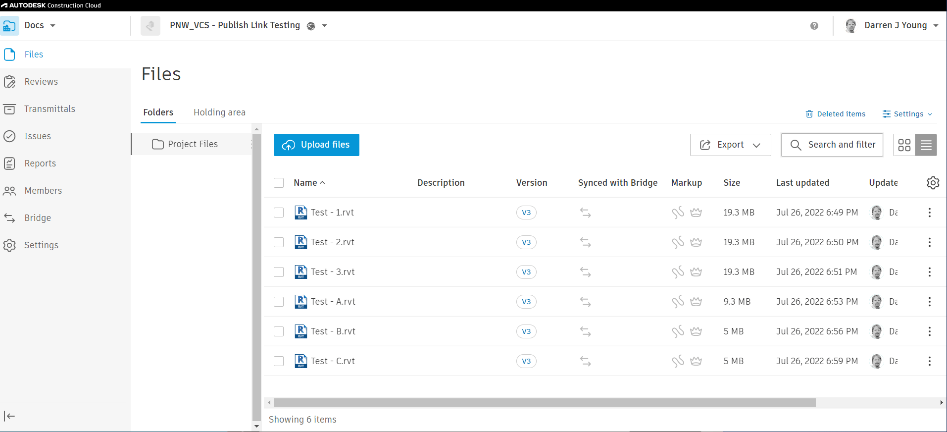
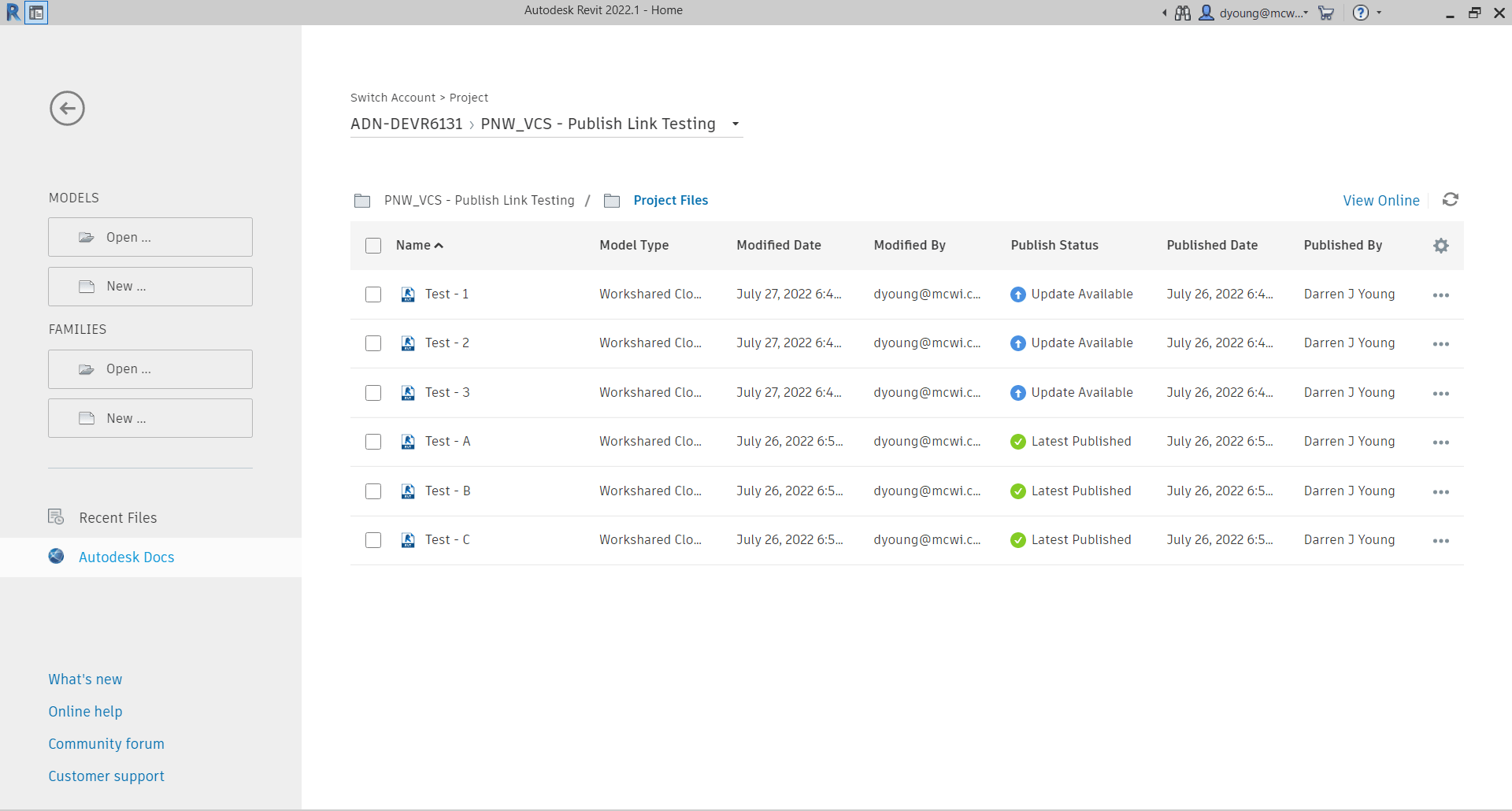
If any of the Revit files were not Cloud Models, they wouldn’t appear here in Revit but would appear from the BIM360 or ACC web interface. You can see in the following image, those same files are listed in the web interface. They were all published so the version in Autodesk Docs displays the same contents as is available in BIM Collaborate Pro.
So far, all seems fine. The files you see in the BIM360 or ACC interface are the same ones that are available in Desktop Connector. Now here’s where the issues starts to manifest itself.
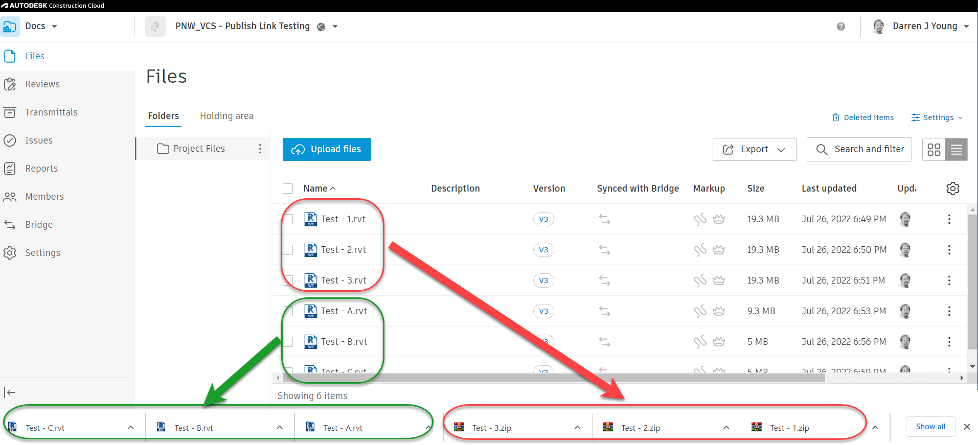
Take a look at what happens when we try to download the Revit Models from the web interface. Set 1, the numerical set download as ZIP files. Set 2 on the other hand, that alphabetic models download as Revit files.
Perhaps you’ve seen this before. I know many users who assume that the ZIP file downloads are there because the Revit files contain links. Because a non-linked model always downloads as an RVT. Other users think it’s part of the whole “Share/Consume” workflow of BIM Collaborate Pro. Both explanations are technically incorrect.
The following image shows the files and their downloaded names. Keep in mind that each set is a model collaborated in the Cloud the exact same way and linked the exact same way. In fact, they themselves are not linked from the Desktop Connector either. They’re linked properly through the “External Resources”. Aside from the files names, they are identical in every way.
Further Proof – RVT Doesn’t Mean RVT
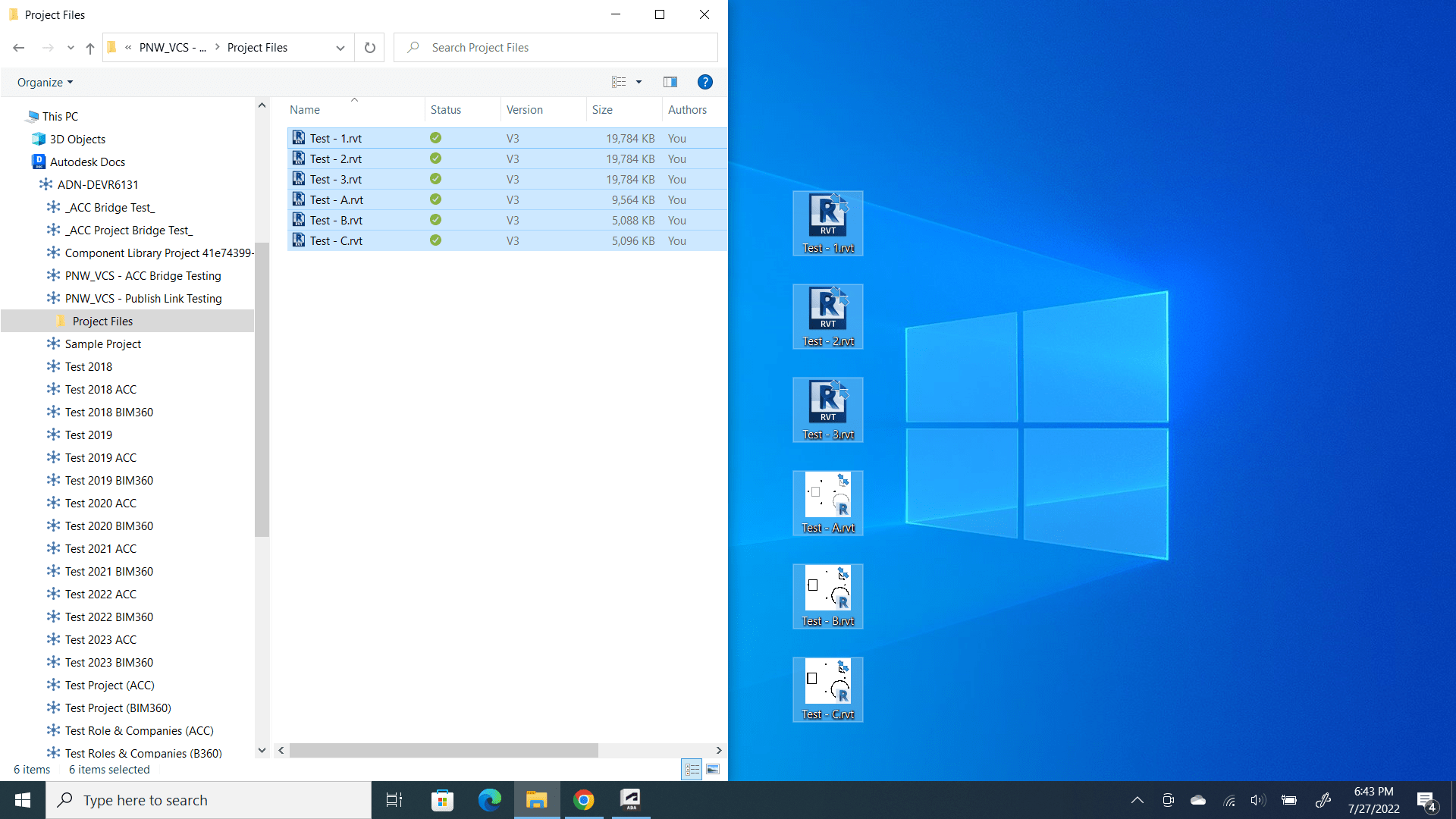
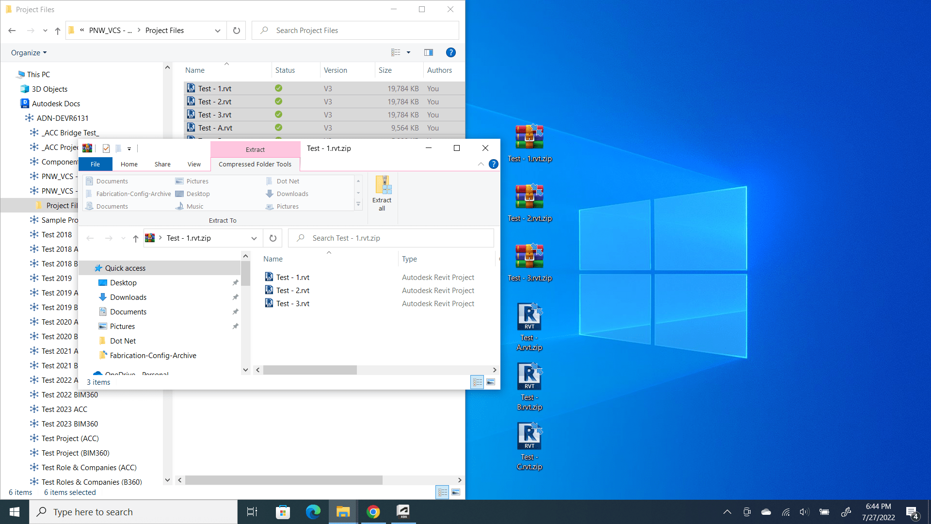
To further complicate matters, Desktop Connector displays all the files as RVT files even though some are ZIP files. Here’s how to test that out. First, we’ll use Windows File Explorer to select and copy all the files to the desktop. You can see the first hints of something being wrong in the following image…
Notice that all the files are named RVT just like was displayed in the Web Interface of BIM360 / ACC. However you can also see the icons are different between the two sets of files. The Revit files display their preview. The others display the icon because if the RVT extension because it can’t find a Revit preview. So let’s test our theory that some of these are actually ZIP files named wrong.
We’ll rename all the files to the ZIP extension and attempt to open them. The following images shows the renamed files. It also shows happens when you attempt to open the ZIP for one of files from Set 1 (Test – 1.rvt, Test – 2.rvt & Test – 3.rvt).
You can see when attempting to open the file TEST – 1.rvt.zip (remember we renamed to a ZIP) it shows the contents. It contains the Revit file and the links that Revit file uses.
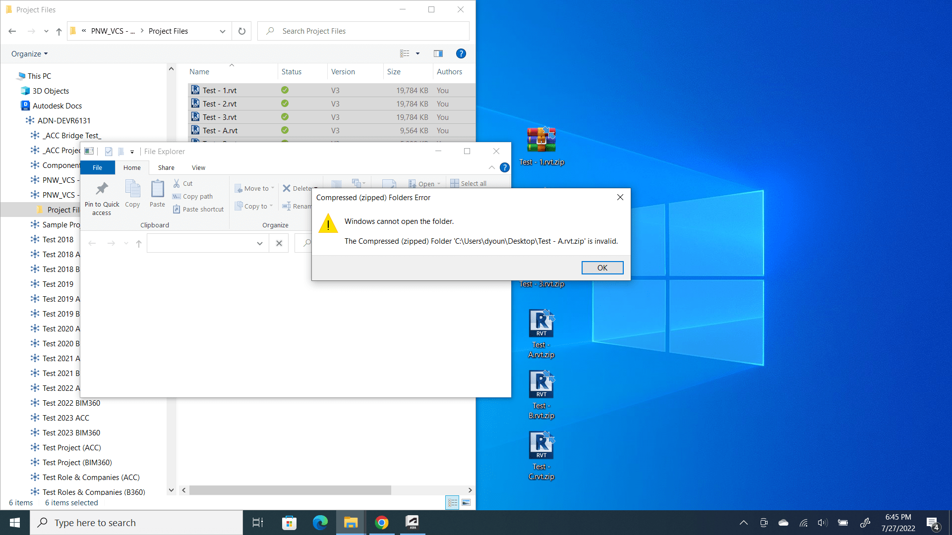
Now let’s try the same thing with another file. This time. we’ll use the file Test – A.rvt.zip from Set 2.
You can see that despite renaming the file as a ZIP file, Test – A.rv.zip will not open and displays no contents. That’s because it is indeed not a ZIP file.
Summary of the Desktop Conector Problem
To summarize what we just saw, the web interface to BIM360 / ACC as well as Desktop Connector showed that all the files were RVT files. But upon testing with 2 different methods (web download & copy/rename from Desktop Connector) we can see that the two sets of files are not the same.
Set 1 is comprised of ZIP files despite showing their name as RVT and Set 2 are actual RVT files.
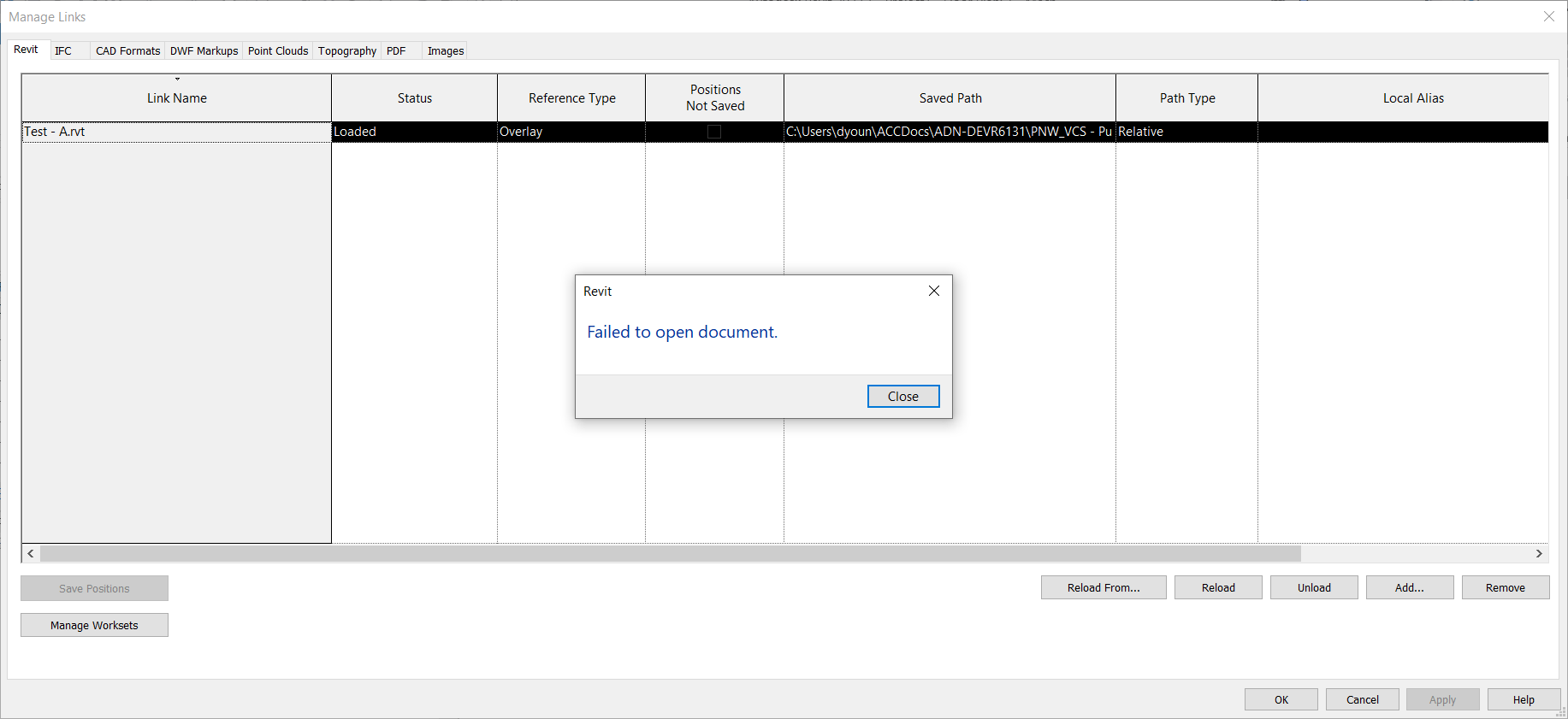
We can perform one further test to see if this is the case, We can start a new Revit file and try to link one of each set from the Desktop Connector. The following images shows just that…
You can see we were able to successfully link Test – A.rvt (from Set 2) using the Desktop Connector. But when we try to link Test – 1.rvt (from Set 1) we get an error, Failed to open document.
Again, this is because despite what you see (the RVT file extension), the file is actually a ZIP file. This is the root of the problem with using Desktop Connector to link Cloud Models. Linking non-cloud Revit models is not a problem. More in that in the next section when we cover “How” and “Why” this happens.
The How and Why
The issue of when BIM360 / ACC is using a ZIP file vs. a RVT file behind the scenes is actually quite predictable and a little controllable. So let’s take a look. It might be a little difficult to understand but we’ll try explain anyway. We’ll then follow-up with the steps to do it yourself.
At the root of the issue is that the Cloud model Revit uses is a separate file that the one you see in BIM360 / ACC Docs and Desktop Connector. You choose when to “publish” the one that shows up in BIM360 / ACC. And here’s where it starts to get complicated. We’ll use the names of the samples models to make it a little more clear.
If you have cloud model Test – 1.rvt open, and you link to cloud model Test – 2.rvt, if cloud model Test – 2.rvt has changes that are unpublished to BIM360 / ACC Docs when you publish Test – 1.rvt to BIM360 / ACC Docs, Test – 1.rvt will be a ZIP file.
On the other hand, if you link to cloud model Test – 2.rvt and it’s latest version is published to BIM360 / ACC Docs then when you publish Test – 1.rvt and download it, it will be a RVT file.
Did you catch that? Whether a Cloud model ends up as a ZIP vs. a RVT depends on the Publish Status of the Cloud models it links when you publish it.
Let’s look at that visually. The below image shows the 3 models from Set 1. Notice how none of them have the current version published. When you publish one of these, or even all three of these you’ll end up with a ZIP file.
Again, the issue is that you linked a cloud model in Revit when that cloud model had unpublished changes. Even if you published all of the models now, you’ll still get ZIP files with downloads and Desktop Connector. That’s because when they were published, there were unpublished changes which made them ZIP files. Further publishes will always make more ZIP files because they now reference Cloud models who’s Published versions are ZIP files not RVT. Yea…that’s a bit complicated. Just know that once you start getting ZIP Downloads, they’ll stay that way. From here on out, there’s only one way to fix it which we’ll get to momentarily.
How Not to get a ZIP
Now here’s where the process get’s slightly different if you want a RVT. The difference here is when you go to link the Cloud model, you need to make sure the file(s) you’re linking don’t have unpublish changes when you publish it. So when you have Test – A.rvt open, make sure Test – B.rvt doesn’t have unpublished changes, if it does, Test – B.rvt needs to be published beforeTest – A.rvt. Then when you then publish Test – A.rvt it will download as an RVT and Desktop Connector will be a ‘real’ RVT file.
So that sounds simple. Just make sure when you link the cloud model that’s it’s most recent version is published. But it’s not that simple. At any point in the future if one of the linked files is not published when you publish the model, you’re back to the ZIP file again and it stays that way. Until you fix it.
Unzipping the ZIP
If you ever link a cloud model that has unpublished changes you’ll end up with ZIP files. Further more, if at any point you publish you model, any one of the linked cloud models has unpublished changes, you’ll get a ZIP file again. And it won’t get fixed again easily.
This is why you should NOT link to cloud models from Desktop Connector. Because you’re relying on the author to understand this and know what to do. In fact, in the course of a real project, it’s damn near impossible to make sure you’re not going to get a ZIP. You can’t control when the project teams make changes and publish.
However, if you do want to fix the ZIP problem, here’s the process.
Open your Revit model and “unload” (not remove) and cloud model links. Save/Sync and publish the model.
Repeat Step 2 for all of the linked Cloud model. Make sure none have the links loaded.
Once all models have their links unloaded, republish them all.
Reopen one of the models and reload the links. Save/Sync the model. One model only.
Now Publish the model and wait for publish to complete before doing any more models.
Repeat steps 4 and 5 for the remaining models.
So that’s the process to “fix” the issue. Each model needs to be republished with none of the cloud model links loaded. You then open one, sync and publish each model. If you do save/sync more than one model before publishing again, you’re back to the ZIP files.
Try It Yourself
This issue is a bit nuanced…what makes a ZIP files vs a RVT. An even when its a ZIP, The web site and Desktop Connector misleadingly tell you it’s an RVT. And if you do have it working, it’s still fragile and breaks easily. Which is why it’s recommended to NOT use Desktop Connector to link to Revit Cloud Models.
If you really want to understand the issue, it’s best to try it yourself. You can do it with just 2 files. Here’s how. Follow these steps exactly.
Step 1 – Create file A in Revit and save as a Cloud model or Cloud Workshared model.
Step 2 – Close file A.
Step 3 – Create file B in Revit and save as a Cloud model or Cloud Workshared model.
Step 4 – Close file B.
Step 6 – Open file A and link file B using the “External Resources” (not Desktop Connector)
Step 7 – Save/Sync file A and close.
Step 8 – Open file B and link file A using the “External Resources” (not Desktop Connector)
Step 9 – Save/Sync file B and close.
Step 10 – Publish both files so their latest version appear in BIM360 / ACC Docs.
Step 11 – Try downloading with model from the web and you’ll see they’re zip files.
– – You’ve now recreated the process which makes the ZIP files – –
Step 12 – Open file A and unload the link to file B.
Step 13 – Save/Sync and Close file A
Step 14 – Open file B and unload the link to file A.
Step 15 – Save/Sync and Close file B.
Step 16 – Publish both models. (when you publish doesn’t matter with links unloaded)
– – Both models are now published with no Cloud model Links. This clears the ZIP issue. – –
Step 17 – Open file A and reload the links to file B.
Step 18 – Save/Sync and Close file A.
Step 19 – Publish file A and wait for it to complete before continuing. This is important. It’s linked to a file B. While file B has no links loaded, it has all it’s changes published (the critical step)
Step 20 – Open file B and reload the links to file A.
Step 21 – Save/Sync and Close file B.
Step 22 – Publish file B and wait for it to complete before continuing. This file is linked to file A which does have links, but it also has all of it’s changes published too.
Step 23 – Try downloading the models now. You should get a RVT file instead of a ZIP.
– – Both models are now published but are now accessible from Desktop Connector or downloadable as RVT files – –
It sounds like a lot of steps but it’s fairly quick to do. Perform these steps and you’ll get a better idea how the issue. Any time you have changes in multiple models before you publish, you’ll see the ZIP show up. If you change and publish a single model at a time, you’ll have RVT files. But also note, once you get the ZIP files, you’ll need to unload the links on all the files, republish and then open, reload and publish one at a time to clear the issue.
Summary
So that’s it. If you understand the issue, you’ll see how easy it is to have the ZIP issue show up. And that’s when linking from Desktop Connector breaks. And in the course of a project, it’s easy for others doing what I’ve explained above to break YOUR link to THEIR model when you use Desktop Connector.
So don’t use it to link Revit Cloud models if at all possible. If you’d like further reading on this, check out these Autodesk Knowledge Base articles…
Your services should not have broken links to ITM’s. Not only is it sloppy database management, it can slow performance of your database.
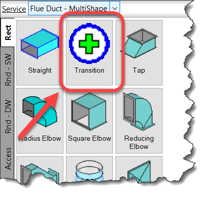
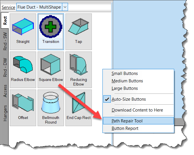
Use the Path Repair Tool to find (and fix) broken links in your services.
Right-Click and empty area of your Service Palette and select Path Repair Tool.
When you run the Path Repair Tool you’ll be asked to select a mapping file. You can click cancel and the tool will continue on. When it’s done, you’ll have a list of broken paths copied to the Windows Clipboard that you can paste into a file.
From this file, you can then create a mapping file. The mapping file is merely a text file in the format….
OLD PATH/NAME,NEW PATH/NAME
So the data you paste from the clipboard is good starting point, it lists all the broken paths. There may be duplicate paths listed if the path is used in multiple service templates. It’s ok to remove the duplicates.
Simply ass a comma after the broken path name and enter the new, corrected path. Once done, you can save the file and use it when you run Path Repair Tool again. It’ll then go and fix all those broken paths.
NOTE: This repair technique does NOT work if you have commas in your folder or file names. (See Best Practice #11)
Does your fabrication shop lack confidence in your drafting/detailing department?
Have you struggled to get buy-in when trying to roll out new processes, technology or deliverables?
Did you wonder why? More importantly, do you KNOW why?
Getting to the Root of Trust Issues
My entire career spanning manufacturing to construction, fabrication shops have had trouble trusting the information they’re given. And there’s good reason. It takes time to master a domain and learn the work. And production staff are busy building and fabricating. They don’t have time to run into the office every time something is wrong. As a result, office staff take longer to train and often persist with producing lower quality work.
But there’s also a lot of reasons that are not good. Downright bad in fact because they’re simple to resolve. Things you’re NOT doing wrong but are causing problems. These trust issues are easily corrected if they’re understood properly. One such issue is fabrication tolerances that I categorize as Shop Math.
The Dynamic Between Tolerance and Rounding
I’ve had trouble explaining this verbally so I figured a more graphic (yet generic) representation would be in order. In basic terms, you need to use a rounding factor 1/2 the amount of your fabrication tolerance to achieve the desired result. As the title of this post suggests, a value of 1/100″ of an inch, can result in a deviation of 1/4″. That’s real Shop Math in practice.
My example uses both fractional inch and decimal to more clearly illustrate the point. You don’t want to get me started in why everyone should use decimal, that’s another post. But decimal also has the same dynamic, it’s just less hidden and more easily fixed. You get a lot less pushback in a shop by adding an extra decimal than by changing the denominator of a fraction to a number the shop says they don’t fabricate to.
Let’s take the following example..,
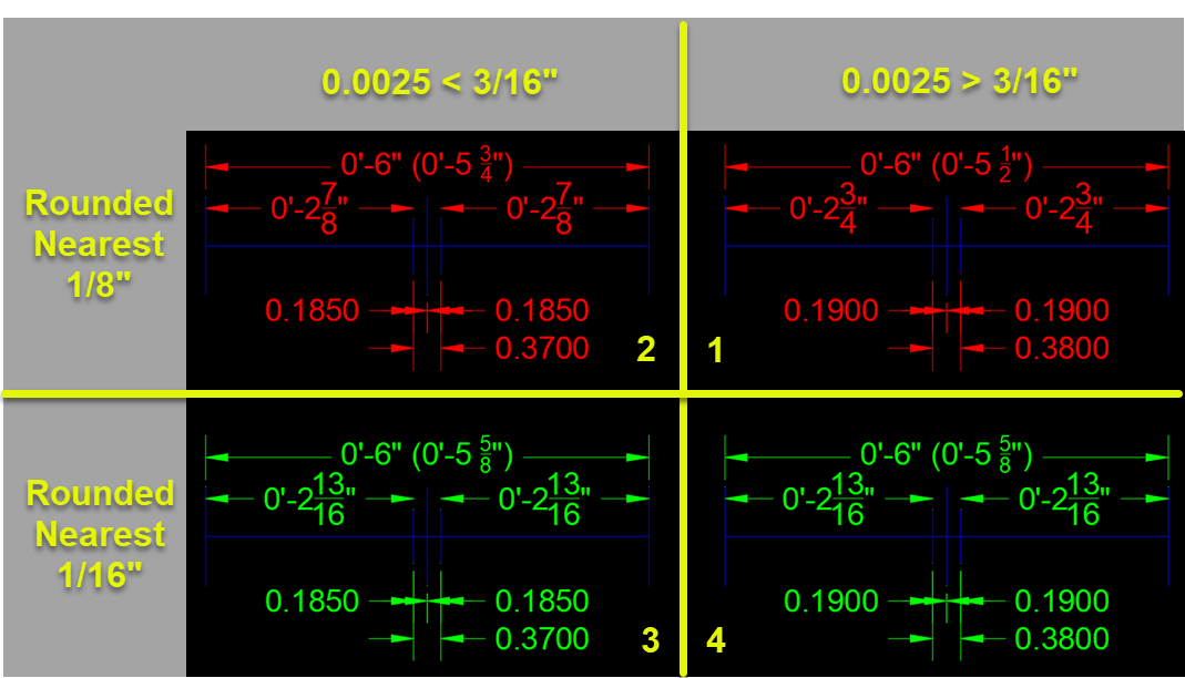
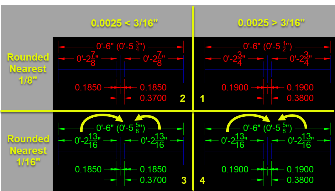
In this example, lets assume our tolerance is 1/8″ (construction field tolerances, that’s fairly common).
The TOP RED dimensions are all ROUNDED to the nearest 1/8″ to match our target Tolerance. A fairly common practice. The BOTTOM GREEN dimensions are all ROUNDED to the nearest 1/16″ which is half our target Tolerance.
Each graphic shows a line 6″ long. Half that is 3″. We’re going to make a gap and dimension from each end to that gap. Maybe it’s a weld joint in pipe or perhaps a mortar joint in concrete block. Doesn’t matter what to illustrate the problem.
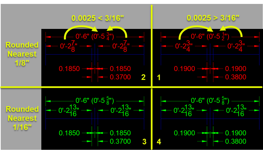
For the graphics on the LEFT (Quadrants 2 & 3), the gap is just shy of 3/16″ of each side of middle to forced the dimension to round UP. For the graphics on the RIGHT (Quadrants 1 & 4), our gap just heavy of 3/16″ of middle to force the dimensions to round DOWN.
Rounding = Tolerance = Confusion = Mistrust
Let’s focus on the TOP RED in the following illustration…
If you take the two parts and add them, they vary by 1/4″. Adding 3/8″ (our rounded gap size) to either of them does not equal 6″ either.
Between these 2 examples, a mere 1/100″ difference in our gap results in a 1/4″ difference and neither adds up to the 6″ of the total length. This is a 1/4″ TOLERANCE because we set ROUNDING to 1/8″ to match our fabrication accuracy.
If you ever wondered why your shop doesn’t trust your drafting/detailing, this is one reason. The Shop Math just doesn’t add up. They see the sum doesn’t add up to the whole and leads them to question the accuracy of your drawing and your staff.
Rounding = 1/2 Tolerance = Trust
Now lets focus on the BOTTOM GREEN portion of our illustration…
Between the left and right (Quadrants 3 & 4) we’re still making the gap just shy and just heavy of 3/16″ from the center. As you recall, we said our fabrication tolerance target was 1/8″ but here, the dimensions are ROUNDED to 1/16″. This is HALF of our target fabrication Tolerance.
Here, it doesn’t matter of the dimensions round UP or DOWN due to the slight variation in the gap, the dimension are the same. Furthermore, if you add the parts, you get 6″.
As you can see, we had different results between rounding UP and DOWN when our ROUNDING value equals the Tolerance we’re trying to achieve. When we round to HALF the Tolerance, those small variations are masked and all our numbers add up.
So if you’re dimensioning for the shop, it’s important to realize this little change can mean questioning or trusting your data and staff. Additionally, if you take the time on the shop floor to explain WHY they see these differences, they quickly realize that the information that leads them to question the data (and your people), is also the very same data that’s most likely to be wrong. What IS accurate and didn’t change, is the geometry itself. This is an extremely critical point to highlight if you’re trying to get your shop to use automation and drive machine tools from CAD/BIM geometry.
The model/geometry, is the MOST right data we have. It’s just not human readable and what we provide as human readable is prone to errors such as these. This is one reason you’re seeing terms like “Model Based Enterprise” starting to float around in the Manufacturing space. It’s also a reason you’re seeing more shop go paperless, eliminating dimensions when possible by leveraging automation.
These efforts can be challenging and often require a leap of faith. But if everybody understands dynamics like this, it can be extremely helpful in moving all of your staff to more digital workflows. Because they trust the geometry and you eliminate what’s confusing them.
This is my 4th and last article on Digital Transformation for the average contractor. The whole point of this series was to help companies understand that they don’t need to know what the future holds to prepare for it. If you missed them, the other 3 articles can be found here…
In this article, we’ll look at an action plan. By using this plan, you can help focus your efforts.
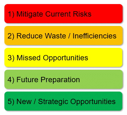
A 5 Step Action Plan
It can help to prioritize with any effort. Because there’s a lot to do, it’s easy to get lost in all the work. Your action plan may look different and it should be if your needs are different. However, these 5 steps are a good starting point.
Step 1 – Mitigate Current Risks
You might have existing risks because of prior actions. You can only mitigating these risks if you identify them. Review what you’re currently doing because that’s likely where they are. However some risks may be due to what you’re not doing. Here’s some ideas to get you thinking….
Is your data backed up? Not just server data but cloud systems, machine tools, etc.
Are you managing user accounts in all your technology systems?
Do your advanced or complex configurations have documentation?
Is your data accurate (BIM Content, Models, Standards, etc.)?
Are users trained in proper processes and technology usage?
Do all your technologies have an “owner” or responsible party?
Is Staff cross trained or does your technology and processes rely on only one person?
Who is maintaining your standards? Is there even governance around them?
Are there things critical to your organization controlled by others outside your organization?
What things have “Single points of failure”?
Step 2 – Reduce Waste and Inefficiencies (Create Value)
Your next step is really something you likely do already. Reducing waste and inefficiency. However it’s a good idea to revisit occasionally. After you’ve documented your workflow, developed a new workflow or changed your technology. It’s good to revisit how these things impact your efficiency and drive value. Some general thoughts that can apply to most company…
Are users aware of how your technology should be used (training)?
Do you have under utilized or misused technology or processes?
Duplicate technology for the same purpose?
Are there things you do that are easily outsourced?
What can be automated but isn’t?
Do new cloud workflows represent what should happen or did you simply move your existing processes into the cloud?
Are your computers or hardware setup consistently, maintained proactively or built with automated processes?
Step 3 – Missed Opportunities
One area people don’t think about enough is missed opportunities. You’re always watching costs vs benefits. Results of doing things. But what’s the cost of not doing something? What’s the cost of missed opportunities? These could come in many forms. It’s best to build your own list but here’s a few examples…
Leverage knowledge from existing staff
Free or joint marketing from vendors or customers
Missed value you could sell if you were leading edge with technology
R&D opportunities with technology vendors
Existing competencies not marketed properly
Step 4 – Prepare for the Future
This step is really what Part 2 and Part 3 of my series was about. These are things you can do now, despite an unknown future. There’s a lot you can do right now that sets you up for success down the road. However you don’t need to wait until the first three steps are done. You can start chipping away at these now. They just shouldn’t be your primary focus until Steps 1 through 3 are well underway. Here’s a few ideas, feel free to add your own…
Document existing processes
Develop ideal workflows
Start building missing competencies in staff and departments
Restructuring existing technology stacks
Capture wisdom of staff nearing retirement
Reverse mentor older staff by tech savvy younger generation
Step 5 – New Strategic Opportunities
This step is the hardest to provide guidance on. It really depends where your company sees itself going. The skills they have can help differentiate itself in the market place from others.
Here’s were an ear to the ground can be helpful. Trying to anticipate what trends in construction may be fads vs long lasting or even transformational. How can you leverage them? How can you change your business to remain relevant? Regardless of the future, if you’ve followed all the other guidance, you should be able to easily adapt when these trends emerge.
Will you be a manufacturer in an “Industrialized Construction” economy?
Do you have staff capable of developing prefabrication or modularization strategies?
Are you able to be an efficient supply chain provider?
Can you help your customers with smart building technology?
Will Machine Learning or Artificial Intelligence render you obsolete or is it simply a tool you use?
Who are the new players in the construction economy and is there value you can bring to them?
How can you capitalize on the struggles of your competition?
Summary
Aside from here in Step 5, everything in this series of posts are things you can start doing right now. They’re things that don’t require a prognosticator’s view of the future. Yet they’re all things that will help you be more agile and able to adapt when trends or disruption comes knocking.
You don’t have to worry about the future to prepare for it. There’s enough to do right now that you can stop worrying. More than likely, at some point you’ll take notice and see you’re living the future. The actions and choices you’ve used to prepare you allowed you to tackle the future without even realizing it.
Make smart choices. Stay busy. Stay Relevant. You can eat the future one small bite at a time.
I discussed the problem and overall objective of digital transformation in construction in Part 1. In Part 2 I outlined four activities you could take right now. Activities that cost nothing more than time. These activities can really help inform you. Guiding where you should start working when aligning your technology stack.
There’s a lot of things you can do to better align your technology. While there’s no magic formula there are a few categories these activities fall under.
In many cases, you might be removing technology from your portfolio. Maybe it’s obsolete or ineffective. Whether your processes have changed or the technology didn’t stay mature it’s best to remove things that are no longer needed or don’t provide the value you were looking for.
It could also be that there’s overlap in solutions. Does more than one product serve the same purpose? You typically don’t want more than one solution for the same problem. There can always be exceptions. But you should have a very good reason if you have duplicate technology.
In many cases, you already have good tech in place. However you may not be using it correctly or to it’s potential. This is often a result of someone solving a specific problem and buying a product to address it. This can result in technology you haven’t fully implemented or is implemented poorly.
This doesn’t mean the solution is bad or that the effort was bad. But it can be helpful to revisit. Is there more value you can leverage? More of your processes and workflows covered? Can you use the product differently to achieve a greater purpose?
When you realign existing tech, it often just takes time. Time to relook at the factors that led to it’s use. Relook at how things have changed. Changes in your process as well as how the product may have matured since first selected.
Can you change your process to better accommodate the product’s value proposition? Can you change how you use the product to better serve your needs? Here’s another case where it only takes time if you have a good tech savvy person in house.
It might also be wise to leverage a vendor or consultant to help. You might also consider leveraging vendors for training. They have experience with other firms using their tools. With their knowledge, they can often can point out use cases you might not have thought of.
The other cost during realignment of technology is licensing. If you’ve under or miss utilized technology, fixing this problem may result in additional use. This translates to additional licensing costs for you. This isn’t bad. It’s good. The whole point is to gain value and productivity. Both of those things should be worth paying for. If not, it’s a sign you’re using the wrong tool.
When it comes to new technology, the number of choices can be overwhelming. You may not know what the future holds. And every vendor claims they’ll lead you there.
The fact is, you don’t need to be a prognosticator to choose good technology. There’s a number of basic concepts and criteria you can use when evaluating technology. Concepts that help you make better choices regardless of what the future holds.
When I look at technology, there’s a number of questions I ask myself about a potential solution. Here’s a partial list of things take into consideration. There is no right or wrong answer. They won’t all be true. But you can get an idea if you have a good solution or not based on these and other factors. When using these criteria, your choice will likely be better suited to the future even if it is unknow. Make your own list or add to this one….
Is it cloud based or enabled? Most things are migrating to the cloud. If it’s an on premises only solution, it’s not aligned with the future as well as a Cloud based solution.
Does it reduce or eliminate paper? Anything that reduces or eliminates paper will help reduce static obsolete data.
Will it reduce or eliminate data files? Much like paper, data files are typically copies of the real data in a system. Think of a PDF, it’s really electronic paper. Give preference to anything that gives you real time access to data without needing “files”.
Is duplication of data reduced or eliminated? Data duplication is never good. It requires extra effort to keep in sync or find out why it’s different. Find solutions that reduce data duplication in your environment.
Will it simplify or eliminate processes? If it makes things simpler, there’s less waste. Less training. Less things to go wrong.
Does it simplify IT infrastructure? Your IT infrastructure can often be impacted by technology. Solutions that simplify your infrastructure can often be an added benefit.
Is it Model based? Can the solution leverage your BIM or CAD models? Not just export data from them or convert them but use them directly to provide value? A Model Based enterprise is what you should be striving for.
Can you integrate it with other solutions? If you can’t integrate with anything else, you’re boxed in. Even if you don’t have anything currently to integrate with, you typically want that ability later should you need it.
Does it have an API (Application Programming Interface) Without an API, you can’t automate anything like data mining or integrating with other solutions. Even if you don’t have a programmer, you may want to use one later. Don’t limit your future options without a good reason.
If it doesn’t meet some of your criteria, does it get you closer? Sometimes we just can’t get everything we want. It might be too much of a change or maybe it’s just not available. But can you get closer? Don’t over look incremental improvements.
Digital twin? Does the solution get you closer to having a digital replica of your product, facility and/or process?
Has manufacturing used a similar solution? Manufacturing has led trends seen in construction by two or three decades. BIM in AEC is similar to PLM (Product Lifecycle Management) in Manufacturing. 3d Parametric Modeling? LEAN? Model Based Enterprise? Prefabrication and Modular construction use similar concepts as DfM, DfA or DfMA in manufacturing that helped re-shore a lot of work that was once offshored.
Have other industries used similar solutions or concepts? Shipbuilding has transformed to use modular. Healthcare leveraged a lot of Toyota’s Lean concepts. GIS uses CAD data linked to external data sets. A lot can be learned from watching others.
Is time eliminated from your process? Any solution should put time back in someone’s day or reduce lead times.
Does it build in quality? If using the solution, will it help mistake proof your processes?
Will the solution require a dedicated administrator? Many solutions sound good on the surface but require a lot of administrative overhead. Verify the cost of administration when looking at any technology.
Is data better organized? Will using the solution help better organize your data and information? Data is of no value if others can’t find what they need.
Can it leverage or use existing data? You have a lot of data already. Can it leverage or use what you already have and provide more value to an existing data asset?
Does it turn data into information? Data is worthless. Information is priceless. Make sure any solution provides information, not just data.
What % of existing data/systems is being used? How much of what the solution offers is actually going to be used or helpful? Features don’t provide value if they’re not going to be used or helpful.
Is the data in system(s) or file(s)? Data that resides in a “system” or database is typically more flexible than in a “file”. File based data typically requires additional management and processes. This makes them prone to user errors.
Can data be captured as a natural byproduct of using the product or does it require a separate work activity? If it takes you a lot of time to log, capture or report on data, that’s a separate work activity. Any system that makes you feel like you need a separate cost code to account for your time just to use it, is likely not a good solution.
Does using the system help standardize data? Standardized data typically yields more value with higher reliability and often eliminates a lot of human error.
Will it help with “Aggregation of marginal gains”? Sometimes a solution’s value isn’t the “one big thing” it does rather that it does or helps facilitate a lot of small incremental improvements.
Can you get a return in 1-2 years? Don’t worry about predicting the future. Tech moves fast. Be cautious of any solution claiming they’re the “Future”.
Is it the lesser of 2 evils? Never a decision anyone likes to make but sometimes a problem is big enough and the benefits in other areas are significant enough that what you do compromise on is the lesser of two evils.
Does it get you closer to your vision? Sometimes you can’t implement the solution you want. It may not exist or it’s just too big a change for your organization to swallow. Don’t dismiss smaller changes over time. Nobody said it’s a permanent solution.
Are Licensing terms flexible? Paying the same licensing cost for part time users as full time is wasteful. Likewise, solutions that want a percentage of revenue can be costly. You can’t always choose licensing terms but they’re often negotiable to a point. Verify the percentage of revenue is revenue from processes the solution addresses. Try to limit licensing costs early on in the implementation…you’re not using the full solution on day one.
Can you replace the solution easily in the future? Nothing is forever. How easily will you be able to swap the solution for another should your needs change?
Your list of things to consider when choosing technology solutions can and should vary. The point is, we don’t have to be able to predict the future with laser accuracy to select good technology. Use common sense concepts and principals and you’ll be well positioned for an unknown future.
In Part 4 (my last in the series), I’ll cover some aspects and approaches to prioritization.
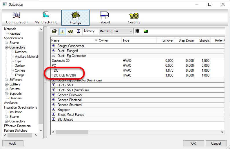
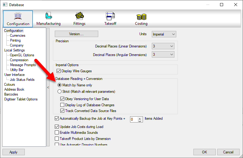
Do you have issues with duplicate entries in your Fabrication Database? These could be proxy entries…those followed by text enclosed within {brackets}. Or they could be identical..if someone made the proxy item permanent,
This can be caused by using the Strict matching setting in your database setting. It’s recommended to use Match by Name only.
When you use Strict naming, when you open drawings or MAJ files, the database settings within those files are compared to those in your configuration. If the data is deemed relevant and it varies, even something as small as a number 3 decimals vs. 4 decimals can add another entry into your configuration.
When using Match by Name only, as long as the name (and group) matches, the entry is considered the same and you don’t end up with duplicate entries.
When I wrote the below article, it was my understanding that Autodesk did not move users to the new user management system when moving your licenses. I’ve since found with the help of another licensing outage for users that this is not the case.
I arrived at work one morning at 6am, I find random users unable to work. Yet another licensing outage. This time, Autodesk moved our AEC Collection licenses to the new management system but a few things were different…
As licenses were moved to the new management system, they were also removed from the “Classic User Management”. No more licenses existing in both places at the same time. This means no grace period which results in NOT being able to preemptively preventing an outage.
Users were copied to the new system system from “Classic User Management” however it was done incorrectly. All network/multi-user license users were assigned single-user licenses. This left a shortage of single user licenses so not all users assigned this license type could be assigned. This is why users were “hit and miss” in their ability to work.
The lesson here is Autodesk clearly doesn’t know what they’re doing and/or is very poor on execution. Once again, they had all the information they need. They knew all the users assigned a single user license and chose not assign different users when transferring licenses.
In short, this means you’re users are prone to a license outage at anytime and there’s nothing you can do about it. All you can really do is be aware and resolve the issue when you arrive in the morning and see idle users.
Original Article Follows…
If you’re a BIM360 Design user, your licenses may be at risk of leaving your team without access. Other license types may be at risk as well depending on your contract, when they were purchased, the type of license purchased and/or when your renewal occurs.
First – The Bad
The BAD news is this is completely preventable by Autodesk but they choose not to do anything. This is why I’m a harsh critic of Autodesk. In October of 2017 when they “Fixed” licensing enforcement for C4R (Collaboration for Revit), teams everywhere couldn’t work due to a confusing license model that was broken and a poor notification process. You can read about that here.
But that wasn’t the only time. In 2019, CEO Andrew Anagnost issued an apology after the 2019 rollout killed prior versions of subscription software. Steve Johnson‘s CAD Nauseum blog has some commentary here.
This time, in an attempt to “Improve” the experience of software managers, Autodesk rolled out new User management. This was previously only available for New Subscription accounts. Now, its slowly being rolled out to existing accounts and can rear it’s ugly head at different times depending what happens with your contract.
In this case, if you had a BIM360 Design account with multiple types (1-pack, 10-pack, etc.) and changed it to a new “Pack” (like a 25-pack), you’ll notice the new license group in the NEW User management section. New products added during renewal or mid-year may show up as well. Nobody really knows what causes a product to migrate to the new setup. Rumor on the street is eventually ALL Autodesk products for all users will be here.
The problem is this…Autodesk does NOT migrate your users to the new Management tools. Your users all have licenses assigned in the “Classic User Management” (the old way to manage users and assign products) but they are not in the “New” User or Product Management. When your old expired contract gets removed by Autodesk, so does your BIM360 Design licenses and your team looses access. Pretty cut and dry. They have all the information they need to make this a non-issue but choose not to. They’re busy taking away your multi-user licenses to provide a “better user experience”.
Now – The GOOD News
While Autodesk knows who your users are, and which licenses they have, they do NOT migrate them into the new system. That’s on you to do. That IS the good news is…that’s on you to do. It’s totally preventable by you.
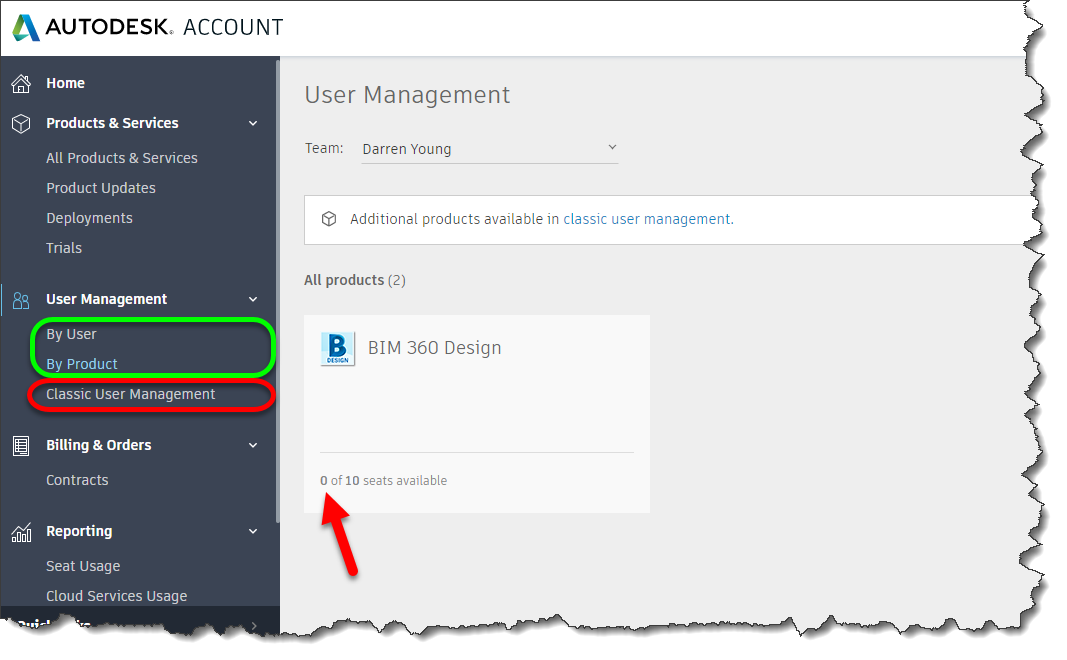
When you renew your contract, review your Accounts Portal. If you see both user management types listed (RED and GREEN in the above image), you need to re-setup your users. First, you’ll go to the By Users section and re-add ALL your users. You can then go to the By Products section and reassign your products to the users that need them. A month or so after your expired contract is cleaned up by Autodesk and removed from your account, your users will still be able to access BIM360 Design services. Failure to do so will result in users being unable to access BIM360 Design from Revit. They won’t work again until you remedy the situation.
Stay On Line – Don’t Trust Autodesk
If you really want to maintain your licenses staying available, you need to be vigilant. You can’t assume Autodesk will provide proactive management. Check your Autodesk portal regularly, especially before and after renewals. Call on your reseller to assist you with questions you have.
This may seem like an isolated instance but I can assure you it’s not. Or else I’m the unluckiest Autodesk customer ever. I have a Developer BIM360 account as well. When renewing that contract, Autodesk didn’t bother to renew the licenses under the contract. No warning. The account just disappeared. Took a day to have them restore it.
As I check my Account Portal regularly, I can’t tell you how many times I’ve been greeted with a warning that not all my products may be displayed or that user management may be unavailable. I’ve checked with industry colleagues who tell me they’ve never seen this of Microsoft and Adobe.
Be skeptical, be vigilant, be Proactive and Stay Online.
Autodesk Fabrication configurations can Compress their data files. It’s a good idea to have this enabled. Not only does this make the files smaller and take up less space, it makes them faster to load. This increases your performance as the data is expanded in memory as opposed to read more data from disk.
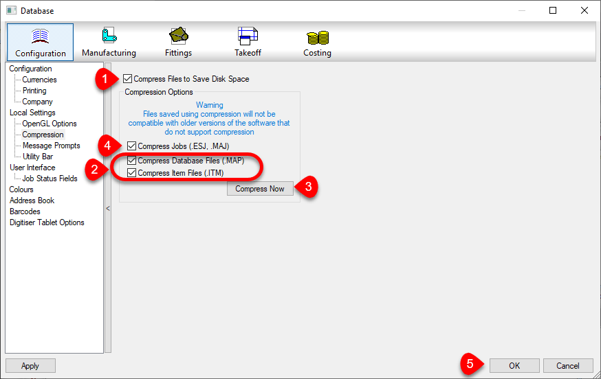
You can enable this option in your database settings. Doing this does not automatically compress existing data that’s not already compressed. The following image shows a suggested sequence of operations. This would both enable compression and compress the existing data.
First Enable Compression by selecting the Compress File to Save Disk Space toggle. Future writes to data tables will be compressed when if they are configured to.
Next, enable the toggles for Compress Database Files (.MAP) and Compress Item Files (.ITM) options. This will tell Fabrication to Compress the existing Database and Item files. Also, “unselect” the Compress Jobs (.ESJ .MAJ) option.
Click the Compress Now button. This compresses the Database and ITM files but will not scan your ESTmep and CAMduct job files.
Once compressed, select the Compress Jobs (.ESJ .MAJ) option. This will compress all Future ESJ and MAJ files but not existing ones. If you wanted, you could have left that option selected in Step 2. However it would significantly increase the time it takes to perform the compression process. Because most of your ESJ and MAJ files are likely past jobs, there’s really no value in processing them now….but you could.
Press the OK Button to save these settings.
Check Settings for Each Product, Version and User of Each Computer
You should also know that these settings are NOT saved in your configuration. The file that stores these settings is located here…
You can tell by the folders, that this setting is stored separately for each user on a computer. Because each product and each version is part of the path, those variations need to be set too.
Because Best Practice #9 tells you to use only one version for database administration, version may seem unimportant. But it IS important to know when you upgrade to a newer version for administration. Those versions should also have these settings reviewed.
Every user who does work in your database, should check each product and version for those settings. If they don’t, your work may compress files while their work may decompressed them.
Because clicking this just once makes it do it’s magic in your database, you don’t need to click the Compress Now button for each version, user, product or computer. The options merely need to be Set., telling those products what they should/should compressed or decompressed.
If you’re a BIM360 Design user, your licenses may be at risk of leaving your team without access. Other license types may be at risk as well depending on your contract, when they were purchased, the type of license purchased and/or when your renewal occurs.
First – The Bad
The BAD news is this is completely preventable by Autodesk but they choose not to do anything. This is why I’m a harsh critic of Autodesk. In October of 2017 when they “Fixed” licensing enforcement for C4R (Collaboration for Revit), teams everywhere couldn’t work due to a confusing license model that was broken and a poor notification process. You can read about that here.
But that wasn’t the only time. In 2019, CEO Andrew Anagnost issued an apology after the 2019 rollout killed prior versions of subscription software. Steve Johnson‘s CAD Nauseum blog has some commentary here.
This time, in an attempt to “Improve” the experience of software managers, Autodesk rolled out new User management. This was previously only available for New Subscription accounts. Now, its slowly being rolled out to existing accounts and can rear it’s ugly head at different times depending what happens with your contract.
In this case, if you had a BIM360 Design account with multiple types (1-pack, 10-pack, etc.) and changed it to a new “Pack” (like a 25-pack), you’ll notice the new license group in the NEW User management section. New products added during renewal or mid-year may show up as well. Nobody really knows what causes a product to migrate to the new setup. Rumor on the street is eventually ALL Autodesk products for all users will be here.
The problem is this…Autodesk does NOT migrate your users to the new Management tools. Your users all have licenses assigned in the “Classic User Management” (the old way to manage users and assign products) but they are not in the “New” User or Product Management. When your old expired contract gets removed by Autodesk, so does your BIM360 Design licenses and your team looses access. Pretty cut and dry. They have all the information they need to make this a non-issue but choose not to. They’re busy taking away your multi-user licenses to provide a “better user experience”.
Now – The GOOD News
While Autodesk knows who your users are, and which licenses they have, they do NOT migrate them into the new system. That’s on you to do. That IS the good news is…that’s on you to do. It’s totally preventable by you.
When you renew your contract, review your Accounts Portal. If you see both user management types listed (RED and GREEN in the above image), you need to re-setup your users. First, you’ll go to the By Users section and re-add ALL your users. You can then go to the By Products section and reassign your products to the users that need them. A month or so after your expired contract is cleaned up by Autodesk and removed from your account, your users will still be able to access BIM360 Design services. Failure to do so will result in users being unable to access BIM360 Design from Revit. They won’t work again until you remedy the situation.
Stay On Line – Don’t Trust Autodesk
If you really want to maintain your licenses staying available, you need to be vigilant. You can’t assume Autodesk will provide proactive management. Check your Autodesk portal regularly, especially before and after renewals. Call on your reseller to assist you with questions you have.
This may seem like an isolated instance but I can assure you it’s not. Or else I’m the unluckiest Autodesk customer ever. I have a Developer BIM360 account as well. When renewing that contract, Autodesk didn’t bother to renew the licenses under the contract. No warning. The account just disappeared. Took a day to have them restore it.
As I check my Account Portal regularly, I can’t tell you how many times I’ve been greeted with a warning that not all my products may be displayed or that user management may be unavailable. I’ve checked with industry colleagues who tell me they’ve never seen this of Microsoft and Adobe.
Be skeptical, be vigilant, be Proactive and Stay Online.