Fabrication Reports – All One Folder

Those of you who used CADmep, CAMduct or ESTmep prior to it’s acquisition by Autodesk remember when all the reports were in one folder. Once Autodesk took over, they moved to a system where each product used a separate subfolder for their reports. After all, ESTmep is likely using different reports than CADmep and yet different than CAMduct. Here’s what your configured reports folders now look like (you may not have all products/folders). Notice how each product has it’s own older.

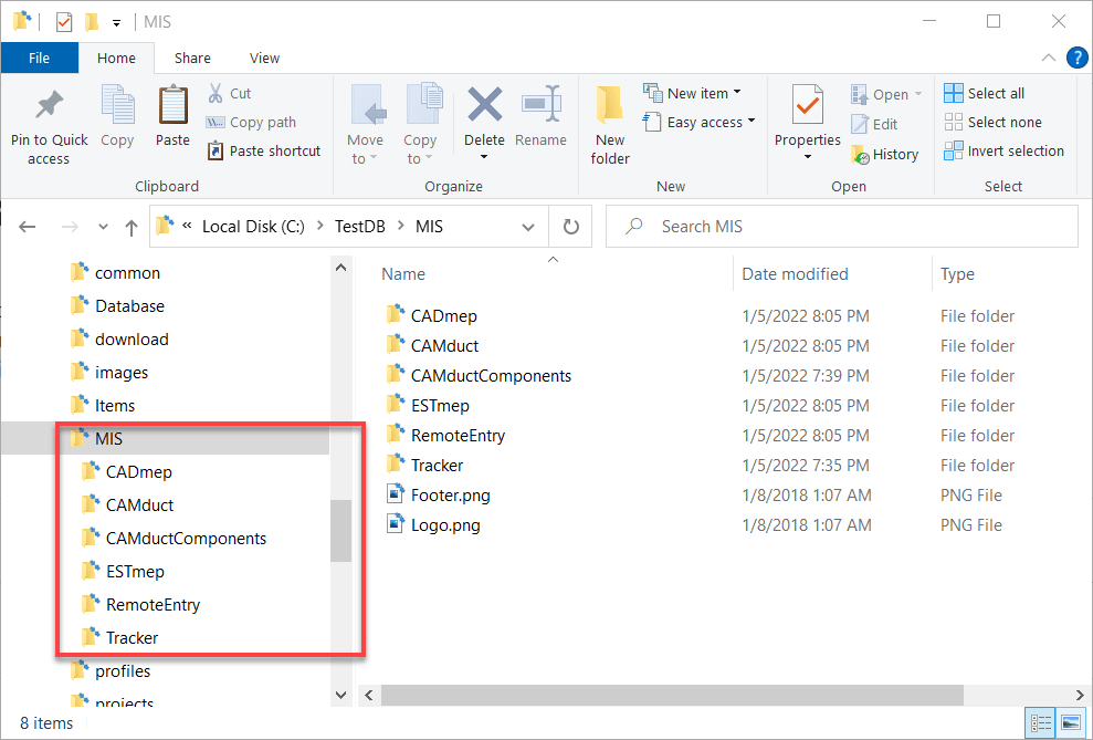
The reality is, many reports are helpful across products. This means you need to make the same report multiple times or copy it from one folder to the others. This leads to duplication of data and a chance than one of the copies gets changed different from the others.


Consolidating All Report to a Single Folder

It’s commonly asked if it’s possible to configure the different Fabrication product to use the same folder. The answer you always hear is No. Technically that’s correct. You can’t configure Fabrication products to look at the same folder. However….

You CAN configure Windows to make multiple folders look at the same folder. It’s just done at the Windows level with a feature called Junction Links.

So lets walk through how to configure CADmep, CAMDuct and ESTmep to all look at the same reports.


Step 1: Find Where Your Reports Are Located

Using CAMduct or ESTmep you can pick Help -> About or type AppInfo at the command line in CADmep. You can then scroll through the window to see where the Reports are located. Alternatively, you could use the Edit Configuration utility to find this folder as well.

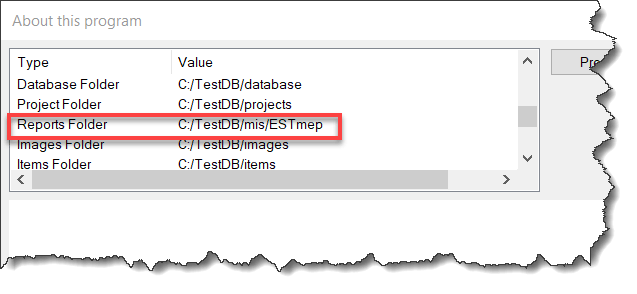
Note that this screencap was done in ESTmep so you see the ESTmep subfolder. The mis folder is actually the root where all your reports are.


Step 2: Copy All Report Folders to a New Folder

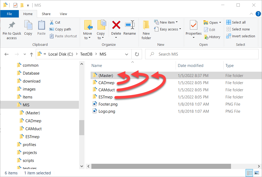
The next step is to copy all the reports from the various product specific folders to a new master folder location to store the reports. In this case, we’ll call it (Master) just to make it super obvious. Notice we also deleted the folders for CAMductComponents, Tracker and RemoteEntry because I’m not using them. You can choose to include them if you need them,


Step 3: Backup and Delete the Original Reports Folders

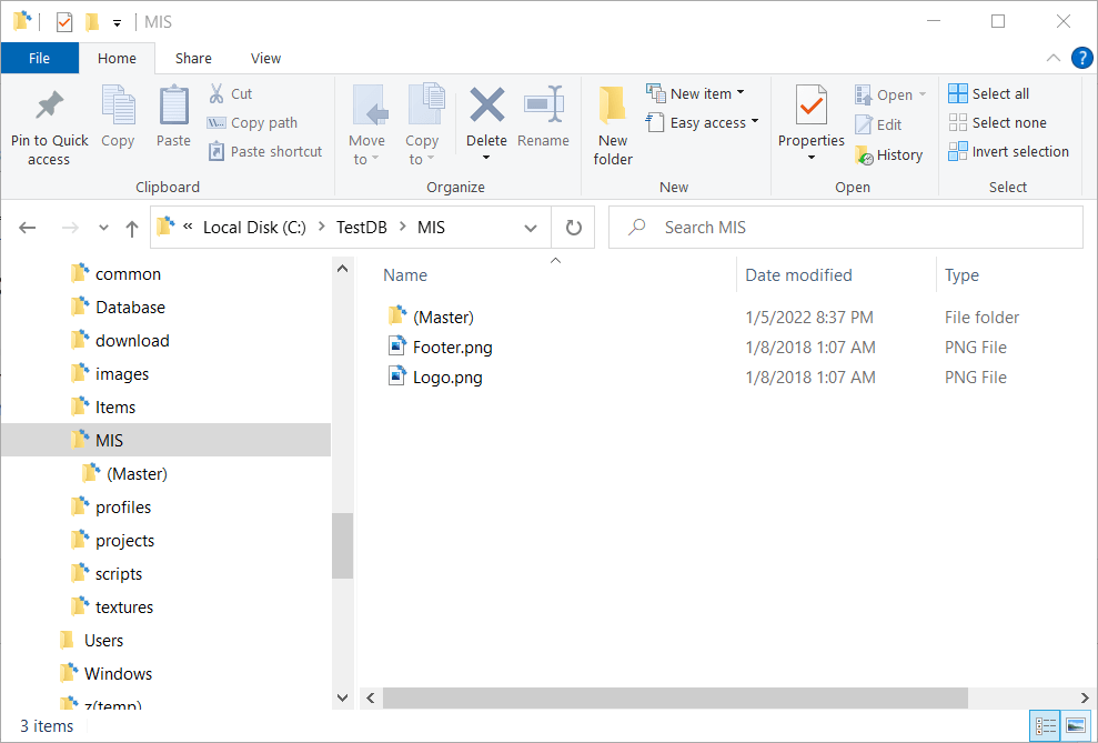
When you’re done, you should back a backup of the product specific reports folders elsewhere incase you want to go back to the original config. Once backed up, you need to delete the original product specific reports folders. When you’re done, your reports folders will look like this…


Step 4: Create Junction Links for the Product Folders

Here’s where we do the magic. Windows allows you to create what’s called a Junction to other folders. A Junction is just another virtual folder that looks at the contents of another. Junctions are how Windows has a “My Documents” folder that really points to “C:\Users\<Username>\Documents“.

To create a Junction you need to open a Command Prompt with Administrative permissions. One that’s done, you use the MKLINK command to make a Junction Link to a Junction Target. The syntax looks something like this….

MKLINK /J "link folder" "target folder"

Here’s a screencap of my DOS Command Window where I make Junction Links to the (Master) reports folder…

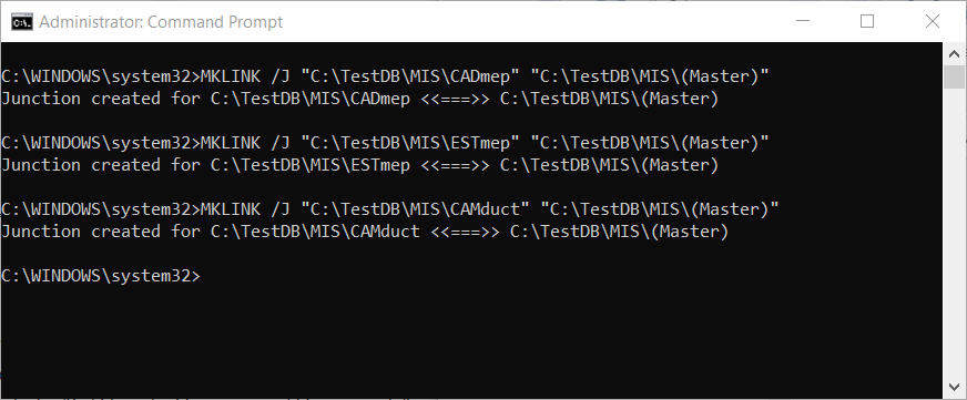
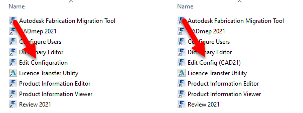
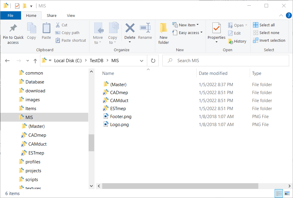
When done (if Successful) you’ll see those product specific folders again for CADmep, ESTmep and CAMduct. But this time, you’ll notice the icons are slightly different and look like a shortcut icon even though the folder acts like a regular folder.

Here you can see a side by side recording of the process happening in real time…


Step 5: Use Fabrication As Normal

Once you have the junctions created, you can use your products as normal. Each fabrication product looks to the folder specific to it, which Windows redirects to the file in the (Master) folder.

One thing to note, is that when browsing the (Master) and product specific folders, the only clue that these are Junction Links is the Shortcut looking arrow on the icon. If you don’t know what’s going on, it would appear that you have 4 folders each with the same files. But if you try to delete the files in one, they will indeed disappear from the other folders too. After all, these folders are Links back to the Target.

Here’s a recording of all 4 folders show at the same time. You’ll see that changes to any one also happen to the others. You may need to Refresh the views to see the changes but they indeed are seen from the Target and all Junction Links. This means that while there’s 4 folders showing the same files, they only take up the size on disk in one folder.


Summary

Junction Links work well for letting all (or some) of your Fabrication products use the same list of Reports. But there are a few noteworthy items to be aware of….

  • Junctions Links and Point to Targets on a different DRIVE or FOLDER as long as it’s on the SAME machine. You can’t make a link to a target from a computer to a server for example.
  • If you access your database from a network location, you need to make make the links from the server so your IT Department may need to get involved. Your local software when accessing the server share will honor the junctions it sees on the server.
  • If you don’t know what’s going on or look closely, it appears you have duplicate data. Make sure you don’t delete things from one folder thinking they’ll still be in the others.
  • If you want to undo this setup, you should delete the Junction Links FIRST just like any other folder before deleting the Target folder. If you delete the Target first, the you’ll have trouble deleting the links.
  • IF you Sync your database from a master source location like Dropbox or using a utility like Robocopy, the Junctions are NOT copied, but are instead copied like regular folders. There may be some special utilities that copy the junctions but I’ve not found them. So what is 4 views of 1 copy of a file on a network, when synced to your local system becomes 4 copies of the files in 4 folders. For the most part, it’s not an issue as you manage from the master source location. None the less, this nuance is worth mentioning. Most Sync utilities do NOT recognize the special nature of a junction and treat them just like a folder.
  • If you want to read more about Junction Links check out this article…https://www.addictivetips.com/windows-tips/create-delete-a-junction-link-on-windows-10/

Windows Quick Assist

Are you familiar with Windows Quick Assist? Windows already had Remote Assistance which can typically require special permissions or setup to work. Windows Quick Assist is more like TeamViewer or GoToAssist and very ease to use.

Quick Assist is a Windows 10 feature that lets you give assistance to other users or receive assistance from other users. No special permissions or setup required other than the person giving assistance needs a Windows account. The person receiving assistance is not required to authenticate.


To start Quick Assistance press the CTRL+WINDOWS+Q keys on your keyboard.

From here, a dialog is displayed giving you a choice to GET or to GIVE assistance.

  • If you intend to GIVE assistance, you’ll be given another window with a code to give to the person you want to help.
  • If you’re going to GET assistance, enter the code given to you and share your screen.

That’s pretty much it. The rest if pretty self explanatory.

If you’d like more details into how Quick Assist works, check out this post on Microsoft’s web page…

https://docs.microsoft.com/en-us/windows/client-management/quick-assist

Fabrication Button Descriptions

Seems obvious once you see it but sometimes the easy things are the most ellusive.

If you’re noticed descriptions on some of your computer’s fabrication palettes and not others, it’s likely the “AutoSize” option you’re looking for.

Right-Click on an open area of the service palette and select the option you prefer. This applies to CADmep, CAMduct and ESTmep. Revit…not so much. Revit likes to do it’s own thing.

Autodesk Fabrication – Determining C1/C2 Connectors in Revit

Fabrication Parts in Revit allow you to edit their connectors just like in CADmep. However, unlike CADmep, you can’t simply hover over a connector to determine if it’s C1 or C2.

So if you need to change a connector, you’re essentially guessing which one to change. Trial and error is at best 50% unless you’re lucky.

So how can you improve this “guessing” based workflow?

Thankfully I have a great network of people smarter than myself. I often get the credit for sharing the information but really, the credit belongs to those who show me. In this case, two of my industry friends showed me ways to improve the odds.


Method 1 – Slope

For this first method, credit goes to Liz Fong from MacDonald Miller. When you place a piece of straight pipe or duct, when you select it you’ll see a Slope indicator (< or >). This by default points to the C1 connector.

Duct/Pipe placed defaults the Slope symbol pointing to C1
Duct/Pipe mirrored also defaults the Slope symbol pointing to C1

There’s a couple downsides to this approach that may apply in some scenarios….

  1. This doesn’t work for fittings. Only Straight Pipe/Duct.
  2. If you click the Slope Symbol, it changes direction and is no longer accurate.
    • This should really only affect Plumbing or sloped Grease Duct systems. Otherwise there’s not a lot of reason to change direction on a non-sloped system.
    • Symbol could still be accidentally clicked and reversed anyway and then be wrong.
  3. Once changed, Slope symbol direction is remembered and there’s no good way to “reset” it.

Still, despite the downsides of this approach, I’m going to go out on a limb and suggest that even on a plumbing system, less that 50% of the slope symbols will be changed from their default. This alone makes this method better than a 50/50 guess like before.


Method 2 – View Cube/Viewing Direction

This next method takes slightly more work, but is almost 100% accurate. Credit for this method goes to Alina Y. from JH Kelly.

In short, from a 3d view, if you make sure the View Cube in the Part Editor window is aligned to the Revit View you’re in, the fittings is oriented in the same direction in the editor as in Revit. You can then select the connector in the Part Editor window and it highlights the connector end associated with it.

Duct/Pipe placed in Revit matches the editor when View Cubes are aligned. Selected Connector highlights.
Duct/Pipe mirrored in Revit matches the editor when View Cubes are aligned. Selected Connector highlights.

This method is almost fool proof and has a few benefits over the sloped method we showed earlier.

  1. Works on Fittings in addition to Straight Duct/Pipe.
  2. Slope direction doesn’t matter.

But we did say Almost. Where this method fails, is if the View in Revit is redefined.

When you set a new Front View, the view in Revit no longer matches the orientation in the Part Editor window as seen in the following image…

Luckily, this is easily remedied by simply resetting the Front View in Revit.

This method also works in Plan and Elevation Views with a slight twist. There’s no View Cube in the Revit window so it’s up to you to understand which viewing angle Revit is in. Next, you can make the View in the Item Editor match but when you look at a connector straight at the edge, you don’t see it highlight. You can then hold the SHIFT key and use the Middle-Mouse Button to slightly rotate the view so that you can see the connector that’s highlighted.

Here you can see what that looks like…


Summary

While not as quick and efficient as hovering over a connector in CADmep, either of these methods or even used in combination can increase your odds of changing the Correct connector on the first try.

While method #2 is more fool proof than method #1, there’s a reason I explain both and here’s how I’d use them both.

For non-sloped systems, the chances the slope symbol is reversed is very low. Because you’re likely selecting the part anyway to edit a connector, a quick glance is all you need to know which connector to change. Quick and easy for straight part on non-sloped fittings. No fuss. No muss. In this scenario, Method #1 is super quick.

For fittings and sloped systems, I would then shift to Method #2. Take a little more time, but it’s certainly quicker than being wrong 1/2 the time and then undoing the connector you just changed and then changing the other. That “trial and error” method results in 3 connector changes when you guess wrong. This is where Method #2 really shines…you get it right every time. If you’re Front View happens to be redefined, it’s easily rest.

Thanks again to Liz Fong (MacDonald-Miller) and Alina Y (JH Kelly) for their great input in coming up with these methods. They’re two of my favorite “Go To” people when I get stumped or need a little help orienting my thoughts.

CAMduct Machine Setup – Axis & Orgin

One of the things that can make machine setup difficult in CAMduct is setting up the coordinate system. This coordinate system must reflect the actual configuration of the machine. Some machines can be reconfigured to swap the axes or set the origin to any corner. This lets you configure the machine to match the software. Others can’t be reconfigured and require you to configure the software to the machine.

It doesn’t really matter where the origin is on the machine, just as long as the configuration in CAMduct matches. Matching the machine isn’t difficult, just as long as you understand what’s happening.

Default Origin and Axis Orientation

In the Machine Setup Dialog, the default Origin is in the lower left. Take a look at the settings and note the X-Axis and Y-Axis directions.

From this configuration, here’s a simulation of the code that’s generated.

If this configuration doesn’t work for your machine, it typically means the machine has a different origin and/or Axis configuration.

Coordinates Rotated 90 Degrees / X-Axis & Y-Axis Swapped

This next configuration rotates the coordinates which results of the X-Axis and Y-Axis being swapped. It also looks like the Origin location changes given the picture, but that’s not the case. This is why Machine Setup can be confusing. This picture does NOT change the origin location. This will become clear shortly.

With this configuration, you’ve now rotated the Coordinate System. When you look at the Simulation below, you’ll that the origin doesn’t actually move. The sheet is still oriented the same way. Long direction is the Rail and the Short direction is the Beam.

What you’ll notice here when looking at the code, is that the Part is Still oriented in the Lower Left Corner of the sheet. However, the X-Axis and Y-Axis are swapped. Additionally, looking at the code on the right, you’ll see how the Y-Axis goes into Negative coordinates. This also isn’t what most machines want, they typically work in positive coordinates but this is easily fixed which we’ll show a little later.

Coordinates Rotated 180 Degrees / X-Axis & Y-Axis Mirrored

This next configuration sets the X-Axis and Y-Axis so that both are mirrored…or rotated 180 degrees.

Looking at the simulation of this configuration, you’ll see both X & Y Axes are using negative coordinates.

Here the both Axes are in negative coordinates and the Part is still located in the lower left of the sheet. Again, not what a machine wants typically, but easily fixed and covered in a little bit.

Coordinates Rotated 270 Degrees / X-Axis & Y-Axis Reversed

Here’s the last configuration. Again notice which way the Axes are oriented.

In this next configuration, the X-Axis and Y-Axis are reversed like before. But this time, the X-Axis is in negative coordinates where as the Y-Axis is in positive coordinates.

Fixing Negative Coordinates

What makes this hard, is that the setting in the dialog makes you think you’re moving the origin of the code. You are not. You’re merely rotating the coordinate system. This is critical when using a machine tool like a Lockformer or Vulcan that uses Trimble’s TookShop controller (formerly called Vulcan). Those are a couple of the most common machines where the X & Y Axis are reversed.

When you look at the simulations, the sheet is still oriented in the same location and the part starts in the same location on the sheet.

You can look at the configuration and see that the Rail is set to the long direction and the Beam is set to the Short setting. Remember this….it’ll be important in just a bit.

For this example, we’ll again use the 90 Degree rotated configuration (our second example) where the X & Y are reversed and the Y-Axis coordinates are negative. You can see in the code, that the Y-Axis is the LONG sheet dimension due to the rip cut along the Rail that’s cut at the end of the program.

Because the Rail Rip Cut starts at Y=0.0 and goes to Y-120.0, you can see that the Origin is still on the left side of the sheet not the right as the configuration screen suggests. Here’s a reminder of the Axis directions…

So if cutting the Rip Cut on the sheet from Left to Right for 120 units means the coordinates go negative, it’s clear the Origin is on the left. To make those coordinates go positive, you need to shift the Origin to the right on the Beam (Y-Axis). You can do this on the Controller tab and entering the shift amount for the Rail.

How, when you run a simulation on this setup, you’ll see the Y-Axis is still the long sheet direction, but they’re all positive coordinates.

Notice on the simulation that the part is STILL on the left side of the sheet and because we shifted the Origin to the right side the Rip cut along the Rail (long side) goes from Y=120.0 to Y=0.0.

You’ve now successfully swapped the X&Y Axis and corrected the coordinates to they’re all in positive units. From here, you can go back and finish configuring all your other preferences like where the parts get nested on the sheet, starting cut location, etc.

Fabrication Job Contains No Parts – Possible Fix?

Have you ever tried importing an MAJ into Revit and received the following error….Fabrication Job Contains No Parts.

There’s a lot of reasons this can occur and it’s NEVER because there are no parts. So much for Autodesk’s QA/QC and Error checking.

You may see this most commonly because parts used in the model contain data that’s no longer in your database. You’ve likely noticed from time to time database entries with curly braces around parts of the name like the following…

This happens when an entry in the database is used by an ITM but the database entry itself later gets deleted. Information is cached within the ITM so when it’s accessed, it creates a Proxy entry in your database if it was missing. Within the {Curley Braces} is the name of the object that created the entry.

While CADmep, ESTmep and CAMduct handle this fairly gracefully, Revit on the other hand does not. When it attempts to load an MAJ, it sees these entries and notices they’re missing from your database and prohibits you from importing the MAJ file. Revit thinks the database doesn’t match the MAJ and stops you cold!

A Possible Fix

If this is cause for the import error, you can use the following COD script to potentially work around the issue….

Take the following script and run in in CADmep, ESTmep or CAMduct. You should be logged in with Administrative Permissions while doing this. This script isn’t fixing Revit or the MAJ. What it’s doing is loading ALL the ITM’s from your Database Library into memory.

The process of loading all these ITM’s into memory creates all these proxy entries in your database. This way, when Revit attempts to import the MAJ, the data associated with those ITM’s are most likely present in your Database configuration. In many cases then results in a successful import of the MAJ.

If the Revit file you are importing the MAJ into already points to a Fabrication Configuration, you should reloaded the configuration FIRST before attempting to import the MAJ.

If for some reason this process still doesn’t work, verify that Revit is reading from the same database location as the version of CADmep, ESTmep or CAMduct where you ran the COD script.

In the event it still doesn’t work, there may be other reasons for the failure but this is often the most common, especially with MAJ’s created recently.

If it does work, you’ll want to use the other scripts I provide on this site to help analyze your database. You likely deleted those database entries in the first place for a reason. You either didn’t realize they were needed, or you didn’t know where they were used to repoint those ITM’s to a proper substitute. Those scripts can help you find which ITM’s use which database entries.

Hope this helps.

Fabrication “Edit Configuration” Utility Documentation

I’ve added documentation for thee Autodesk Fabrication Edit Configuration utility to the site. You can find it here or in the Fabrication menu.

This utility is fairly misleading. Because it prompts for a Database Configuration, most people think the settings apply to the selected configuration. While some of the settings are saved in the MAP.INI and therefor specific to a database configuration, not all are. Many are saved in the Windows Registry.

How Settings Work

Settings stored in the registry need to be made for each program, program version and user. That is, if you make changes to settings stored in the registry using CADmep, they only apply for CADmep. If you’re using ESTmep, you need to make the changes there too. Additionally, if you use the utility that ships with the 2020 version of CADmep, they won’t apply in the 2021 version of CADmep without making the changes there too. Lastly, the only apply for the user who is currently logged in. Log in as another user and all those settings needs to be changed again.

This is the reason I typically make the changes directly using registry edits or automation that imports the registry changes. This allows me to ensure I’ve not missed anything and that they get set no matter the user.

Edit Configuration Utility Tricks

The Edit Configuration utility itself is confusing. The utility ships with each Fabrication Program (CADmep, ESTmep, CAMduct, CAMduct Components, Remote Entry and Tracker). The same utility will present slightly different options depending which folder it is run from. And to add to the confusion, the shortcuts are all named identically.

To make it easier, I go to the folder with the shortcuts and rename them. From “Edit Configuration” to “Edit Config (CAD21)” and similar. This helps me know which program I’m calling the utility for.

Even if you don’t edit the MAP.INI file or Windows Registry directly and instead use the utility the documentation is helpful for letting you know where the settings are stored. This helps you know how to edit them to your needs.

Updated From Prior Documentation

If you’ve attended any of my prior Autodesk University or MEP Force conference presentation, you may already have a copy of this documentation. However, I’d encourage you to use the version I’ve posted no this site. Not only did I add information for the CAMduct Components, Remote Entry, Tracker and Fab Review applications, I’ve also fixed some errors and typos in the prior existing data.

Stratus Dashboard Header Trick

Quick little Stratus tip. This on for headers on your Dashboards. A normal dashboard doesn’t have the ability to customize the header. However, being Stratus is a web based application, you can inject some simple HTML tags to perform some limited modifications.

Take a look at the following headers….

These headers are a result of inserting some very simple HTML tags. Here’s a look at the Report configuration for these header modifications…

Here’s an explanation of these HTML Tags…

HTML Tag(s)DescriptionUsage
<br>Break Line / Carriage ReturnPlace between text to create a
new line
<i> </i>Italics Text placed between these tags will be italic
<u> </u>UnderlineText placed between these tags will be underlined

A few things to note…

  • You can nest <i>Italics</i> and <u>underline</u> to transform text to <i><u>both</u></i>.
  • More complex HTML tags don’t work, there’s just too many special characters.
  • HTML tags may (will) show in other places like in the output of CSV files and/or other types of reports.

The usage of HTML tags in your Dashboard headers is likely not supported. If you find any errors within Stratus on pages that you’ve used these, you may want to remove them to verify the special characters aren’t the cause of your issues.

Merging Autodesk Fabrication Databases (Method 4 of 4)

Warning: This is last part (4 of a 4) in a series on merging Autodesk Fabrication Databases. Autodesk Fabrication software is extremely powerful and flexible but that also makes it very fragile. Use the below guidance with caution. I highly recommend backing up your configuration before attempting anything I’ve recommended. It never hurts to have a firm grasp of how Autodesk Fabrication functions from an administrative perspective. Consider yourself warned!

Method 4: MERGEDB (CAMduct only)

This last method is very quick and powerful but only available in CAMduct. If you’re not a CAMduct user, simply download and install to perform this process while in the 30-day trail period.

This method doesn’t let you pick and choose individual database entries but you can pick certain database types and quickly merge all of them into a new configuration. Unlike prior methods were you typically started in the old Database to export an *.IOX / *.IEZ file or create a Proxy ITM first, in this process, you start with the database you want the items to be imported into.

In addition to make of the database entries Method 1 supported, this method also supports these additional entries.

CutoutsLeadsRates
FacingsMaterialsSilencers
Hanger SpecificationsNotchesVanes

To use this method, start CAMduct and type CTRL-SHIFT-C to display the command window as shown below.

From the command window, type MERGEDB and press <Enter>. This doesn’t do anything other than tell you the data the command needs as shown below. The Strict/Unstrict options tell the merge process if it should only look at the name or the data to determine if it’s duplicate. If you choose strict and the items are already in your database, something as simple as 3 vs 4 digits after a decimal will cause a duplicate entry. In most cases, unstrict is all that’s required.

For this example, we’ll type MERGEDB UNSTRICT NOTCHES to import all the notches from one database to another as shown below.

When you press enter, you’re prompted to select a folder. You should select the Database folder of the old database you want to merge into your current database.

If new items are found, you’ll be notified and prompted if you want to save the changes or not.

Upon completion of the merge, you’ll need to go to those items in your database and make permanent any you intend to keep and remove those you didn’t want.

Pros:
> Only way to import some database entry type.
> Easiest way to merge the bulk of 2 database together.
> Extremely fast and efficient.
Cons:
> Requires CAMduct.
> Can not pick and choose database entries, only database types.
> Requires post merge cleanup of deletion or making entries permanent

Merging Autodesk Fabrication Databases (Method 3 of 4)

Warning: This is Part 3 of a 4 part series on merging Autodesk Fabrication Databases. Autodesk Fabrication software is extremely powerful and flexible but that also makes it very fragile. Use the below guidance with caution. I highly recommend backing up your configuration before attempting anything I’ve recommended. It never hurts to have a firm grasp of how Autodesk Fabrication functions from an administrative perspective. Consider yourself warned!

Method 3: Service Export/Import

This method is very similar to Method 2 above except that it works on a full service and all the items within it’s service template. If you have an existing service you want to post from one Database to another, this is a great method. Even if you just have a library of multiple ITM’s, it’s very common to create a transport service. That service holds those ITM’s and can be used as a means to get ITM’s from one database to another. Here are the steps.

From CADmep, type EXPORTSYS at the command line or in ESTmep or CAMduct, while in the Takeoff screen, select Takeoff -> Services -> Export as shown below…

This displays the Export Systems dialog. Use the Browse button to select the location and name of the *.IEZ export file. Select the service(s) you wish to export and click the Export button.

Importing is a similar process. Type IMPORTSYS from CADmep or from the Takeoff screen in ESTmep or CAMduct, select Takeoff -> Services -> Import as shown below…

You are prompted to select an *.IEZ file for import. The file will be read and display all the services that were exported. Select those you want to import and click Import.

Because IEZ imports can contain a lot of data, it’s likely you may have a lot of duplicates. Upon import, you are prompted if you’d like to Import ALL or NEWER item. Select as appropriate for your situation as shown below.

If Estimating data is found, you are also prompted to Replace or Keep existing tables. Because the database you are importing to is likely your current desired database, I’d recommend to Keep existing tables and only Replace if you intend to bring over labor and cost data in the Import. Once again, choose the option that best suits your needs as shown below.

Like in Method 1 earlier, if the import finds a service or template it thinks is the same, it’ll prompt you how to proceed. I highly recommend NOT selecting the “….To All” options as it’s common for the database index to cause false matches and mislead you.

You are prompted once the import is complete. As with Method 2, if ITM’s imported through this process contain new database entries, you’ll need to find those and make them permanent in a similar way.

Pros:
> Easiest way to import large numbers if ITM’s and their related database entries.
> Easy way to import Services and Service Templates
Cons:
> Slowest of all process do to all the verification the Import process needs to do.
> Can Import a lot more data than you intend.
> Can not pick and choose individual database entries to import

Stay tuned for Method 4 in my next and last post in this series.