Beware! – Revit & Desktop Connector
If you use BIM360 Design (formerly “Collaboration for Revit” a.k.a. C4R) along with the Autodesk Desktop Connector, you should be aware of a common mistake that can lead to data loss.
BIM360 Design or C4R as the older version is called, is used to store Revit models in the cloud on Autodesk’s BIM360 platform. BIM360 Design using the BIM360 Docs platform as storage platform. C4R on the other hand uses the older BIM360 Team for storage of the Revit models.
While you could (can) upload your Revit models via the web interface to either storage platform, Revit would not see these files. They needed to be enabled for Collaboration and uploaded through Revit. This process made changes to the Revit files which enabled collaboration from BIM360 Design/C4R.
while Revit models need to be uploaded this way, there was no other way to upload other files types besides the web interface. Even if you did upload AutoCAD, IFC, Navis or other files types that Revit can link, there was no way to link these files into Revit from the BIM360 platforms. If you linked them from your server, the other members of your team without access to your server would not have access.
Autodesk Desktop Connector was created for this purpose. While you can’t link a non Revit file type into Revit directly from BIM360, you can use the Autodesk Desktop Connector to sync those other files types locally to your computer. Any other team members also using the Autodesk Desktop Connector would then also have access to those same files and the links would be identical.
What’s the problem?
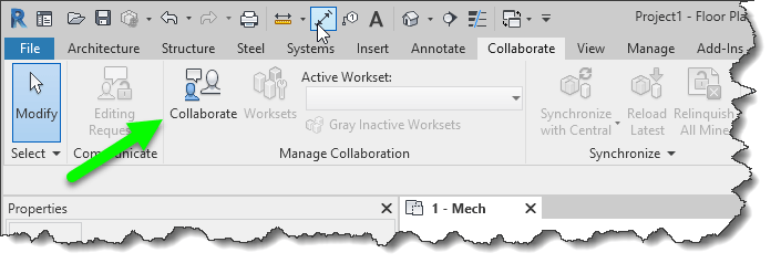
The common problem that comes up when using BIM360 Design/C4R along with the desktop connector is Autodesk’s unfortunate choice in using the same icon for both products.
Depending where you see the icon, you get different results. If you click the one that references BIM360 collaboration services you’re good. If you click the one that references the Autodesk Desktop Connector, bad things can happen.
When a file is enabled for Collaboration and you open it through the Autodesk Desktop Connector, Collaboration is disabled and the file is configured as a local file or central file like you’d typically use of a file server. When this happens, the file is seen as being different and will not sync back to the BIM360 platform.
What this means then if that you have two different version of the file. One stored locally from the Autodesk Desktop Connector and another cached locally when opened from BIM360 Collaboration service (BIM360 Design / C4R) When you look at BIM360 Docs or BIM360 Team portals, you only see one version.
How do I know I’m using the correct Icon to open my Revit file?
Depending on the particular versions of Revit and their update versions, your install of Revit may appear different but the underlying concepts are the same. For these images, Revit 2018.3.2 and 2019.1 were used.
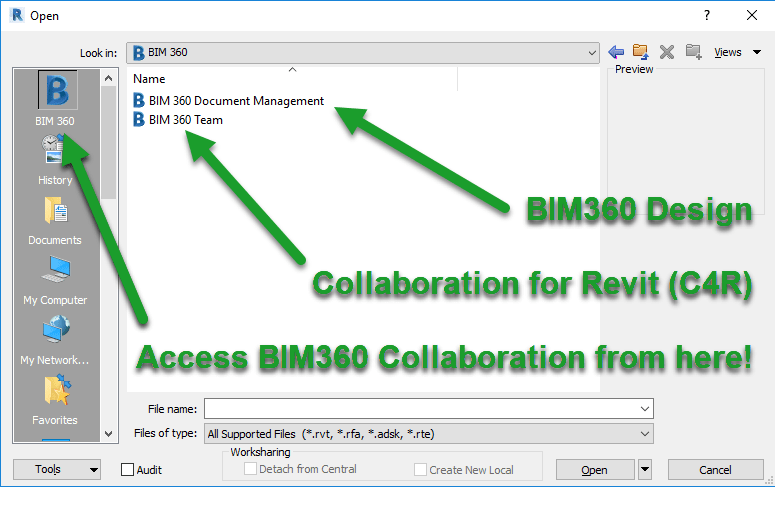
When opening a Revit model from 2018, you’ll see the “B” shortcut in the left. This is the proper way to open BIM360 Design/C4R enabled files. BIM360 Design and/or C4R sites will be listed depending if you have been given access to projects within those sites that use 2018 version of Revit.
When opening a Revit model from 2019, you’ll also see the “B” shortcut in the left. The same as with 2018 versions, this is the proper way to open BIM360 Design enabled files. BIM360 Design only will be listed because 2019 doesn’t use BIM360 Team/C4R. If nothing is displayed here, you may not have been given access to projects within those sites that use the 2019 version of Revit.
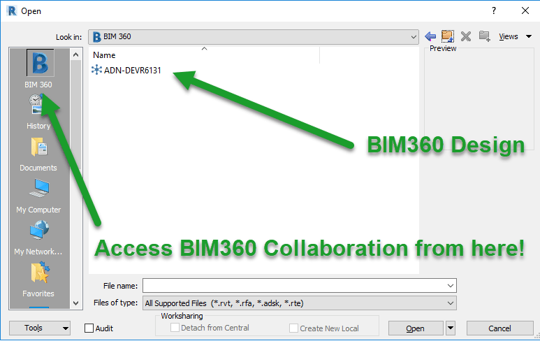
The other place you may see the BIM360 icon is from My Computer or other shortcuts that look at your local system. The following image shows 2018 when using the incorrect shortcut because it instead points to the Autodesk Desktop Connector drive on your computer.
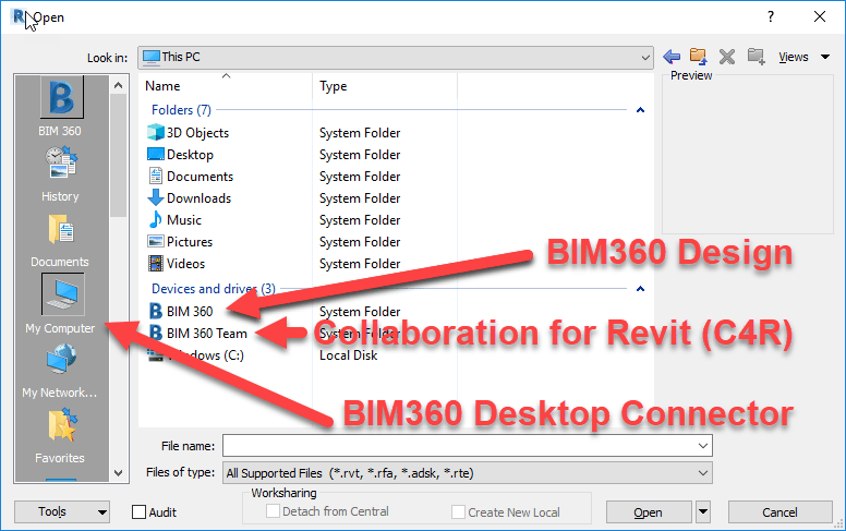
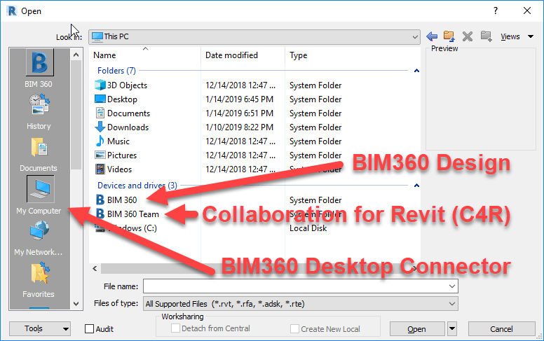
And once again, 2019 versions of Revit are similar. On clue is that here, even though 2019 doesn’t support C4R, they are listed here. This is because you’re not accessing via Revit’s collaboration tools, you’re simply accessing a special local drive on your computer that’s syncing everything in the BIM360 platform completely independent of Revit.
More clues when opening Models from the Recent Files List
If you’re trying to open Revit models using the Recent Files list, there’s a few subtle clues that tell you if you’re opening a collaboration enabled BIM360 model or simply opening a model from the Autodesk Desktop Connector drive.
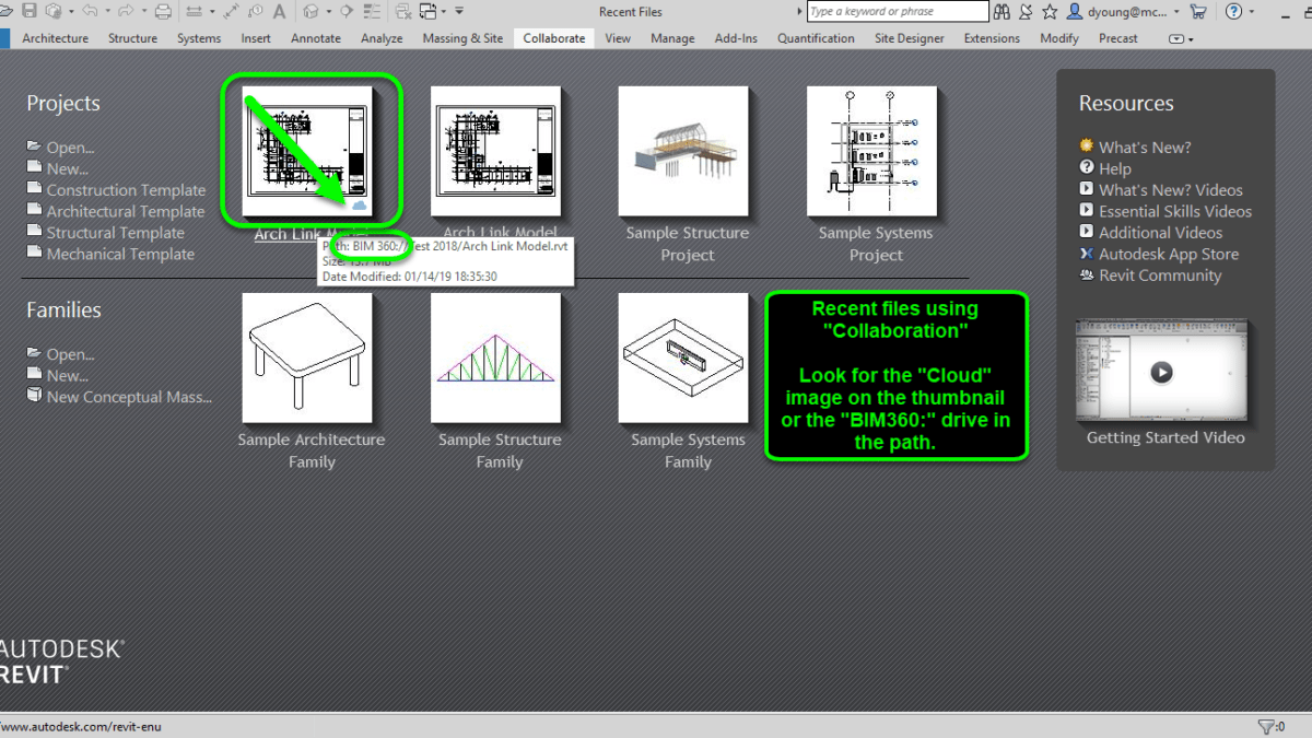
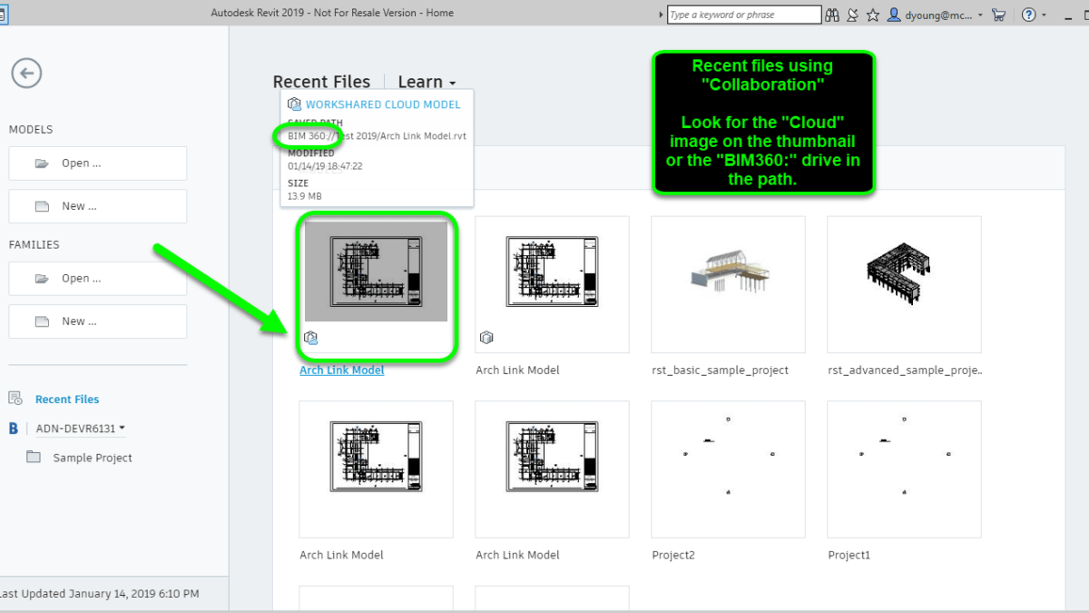
The following image shows Revit 2018 with a BIM360 Design/C4R model correctly. Notice the drive letter in the path as well as the “Cloud” image in the thumbnail.
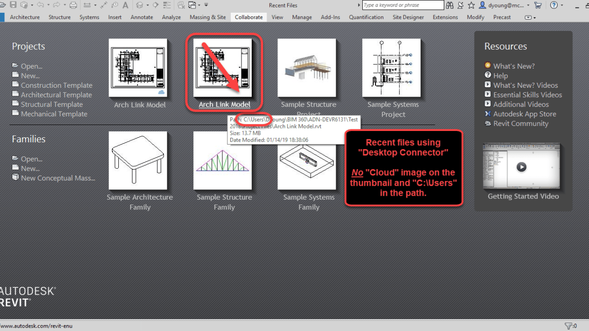
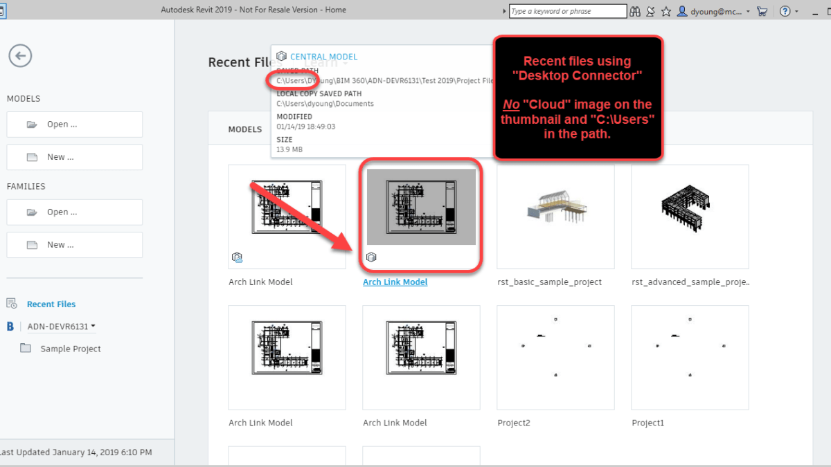
The following image shows Revit 2018 with a Recent File that was accessed incorrectly from the Autodesk Desktop Connector. Notice the path will point to your Users folder on your computer and there’s no “Cloud” image on the thumbnail.
Similar to 2018 but formatted differently, Revit 2019 displays the same details in it’s Recent Files. The following image is 2019 showing a recent file opened correctly through BIM360 Collaboration tools.
And one more image below that shows a recent model opened incorrectly from the Autodesk Desktop Connector.
Additional Clues
Looking at some of those subtle options can easily be overlooked or forgotten. Especially in the daily stress of production and deadlines. There are a few more obvious clues that can tell you if you’re opening your Revit models correctly.
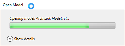
For starters, when you open a BIM360 Design or C4R model properly in Revit, you’ll see a nice status dialog indicating that the files is being opened and sync’d locally.
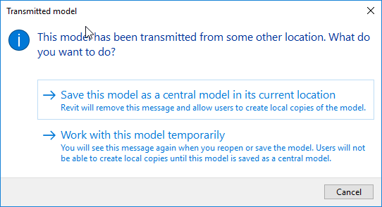
On the other hand, there’s a major red flag when you open the files incorrectly though the Autodesk Desktop Connector. When you open the files incorrectly, you’re prompted to work on the model temporarily or save it locally as a Central Model. If you see this dialog, you know you opened the file incorrectly and should click the Cancel button.
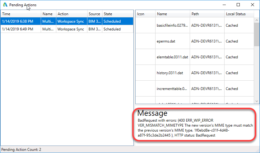
If for some reason you or another user did open the file incorrectly, you can use the Autodesk Desktop Connector icon in the Windows System tray to review the pending actions. There will likely be warnings when reviewing the connector’s syncing status tasks. Note however that that lack of pending tasks with errors does not mean a file can’t been opened incorrectly. Any number of other actions could have overwritten the local copy or cleared those actions.
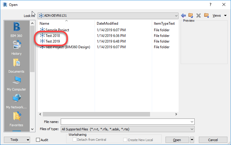
Another subtle clue is that if you look at the collaboration hubs and you see multiple projects that use different versions of Revit between them, you know you’re opening the models incorrectly. The Autodesk Desktop Connector display all projects, regardless of Revit version being used because it;s independent of Revit. When opening files correctly for BIM360 collaboration, Revit 2018 will only see 2018 project versions and Revit 2019 will only see 2019 project versions.
Again, if you don’t see differently projects that use different Revit versions, that does not mean you’re opening them properly. You merely may have been granted to projects of only one Revit version. But if you do see multiple projects you know are using different versions of Revit, it;s a sure sign you’re opening the files wrong.
Best To Avoid Using The Dropdown
The last word of warning is with using the drop down list in the Open dialog. Depending when and how you’ve accessed Models, neither BIM360 icon may be present, one or the other may be present, or both BIM360 icons may be present. Because they have no description, its hard to tell wich does which.
The following image shows the Dropdown list expended with both BIM360 icons displayed. One will take you to the proper BIM360 collaboration tools and the other, incorrectly to the Autodesk Desktop Connector.
Because of this very subtle difference, it’s likely a best practice to not use them ever. If they don’t show up on your system, don’t worry. They typically won’t display until you’ve first accessed the corresponding My Computer or BIM360 shortcuts on the left side of the dialog.