AutoCAD Selection Modes

AutoCAD does a lot of things for you automatically. Unless you’re an old timer from back in the DOS days, you may not be familiar with all the options you can choose from when presented with the “Select Objects:” prompt in AutoCAD, In days of old, AutoCAD displayed all of the options on the command line when going into selection mode. There were less options back then and a lot of what happens automatically now, you had to type the options for,

Today, there’s a lot more options so AutoCAD no longer displays them unless you type an invalid entry. Even then not all the options are displayed. Many of the options now are default behavior making the options less critical in operating AutoCAD efficiently. None the less, they are often helpful. Here’s a chart of the options available. A description of each option follows. For more detailed information, you can refer to AutoCAD’s Online Help using the following link.

AliasOptionModal / Single Use
AAddModal
ALLEverythingSingle Use
AUAutoModal
CCrossingSingle Use
CPCrossing PolygonSingle Use
GGroupSingle Use
LLastSingle Use
MMultipleModal
OObjectModal
PPreviousSingle Use
RRemoveModal
SiSingleModal
SUSub-ObjectModal
UUndoSingle Use
WWindowSingle Use
WPWindow PolygonSingle Use
  • Add (A) – Default mode for selection in AutoCAD. As you repeatedly pick items, they are ADDED to the selection set you are building. Stays in effect until switching to REMOVE mode.
  • All (AL) – Single use option that selects ALL objects in your AutoCAD drawing even if not displayed outside the current drawing area. Object on layers that are OFF and/or LOCKED will still be selected. Objects on layers that are FROZEN will not be selected.
  • Auto (AU) – Default mode for selection in AutoCAD. It’s combination of two other AutoCAD selection modes combined. SINGLE if you pick on an object, it will be selected. If you don’t pick on an object, BOX selection mode will be a CROSSING if the second point is to the left of the first selected point or a WINDOW selection  if the second point is to the right.
  • Crossing (C) – Single use selection mode where you pick two points to form a rectangle. Anything completely within or crossing the rectangle, regardless of the order or direction the points are picked is selected.
  • Crossing Polygon (CP) – Single use selection mode where you picks a series of points to form a polygon. Any object completely within or crossing the polygon will be selected.
  • Group (G) – Single use selection mode that allows you to type the name of a group to add the objects in that group to your selection. When specifying the names of unnamed groups, you must include the asterisk (*) prefix in the automatically assigned anonymous name AutoCAD gives it.
  • Last (L) – Single use selection mode that allows you to select the most recently added object in the drawing that’s visible, in the current drawing space and who’s layer is not off or frozen.
  • Multiple (M) – Modal selection mode used to selects objects individually without highlighting them for performance when selecting complex objects. When finished selecting objects you don’t want to highlight, press Enter and you’ll be returned to the default AutoCAD selection mode and still in the select objects prompt.
  • Object (O) – Default selection mode in AutoCAD where you select objects. Use this option to exit the SUBOBJECT selection mode.
  • Previous (P) – Single use selection that selects everything that was in the previous selection set (assuming the previous selection set wasn’t erased).
  • Remove (R) – Modal selection mode that cancels the default ADD mode to remove objects from your selection set. Most useful when it’s faster to select everything (ALL) and remove what you don’t want selected than it is to select everything you do want selected.
  • Single (Si) – In addition to being a single use selection modem, you can only select one object and the select objects prompt is terminated. If you fail to select an object in SINGLE mode, you are switched to BOX mode.
  • SubObject (SO) –  Model selection that allows you to select edges, faces, etc of complex objects. When in SubObject mode, you can no longer select Objects without using the OBJECT option to return to that selection mode.
  • Undo (U) – Single selection mode that removes the most recently added object (or objects if they were selected as a group) from the selection you’re building. Can be used repeatedly to keep removing object(s) in the reverse order they were added.
  • Window (W) – Single use selection mode where you pick two points to form a rectangle. Anything completely within the rectangle, regardless of the order or direction the points are picked is selected. Unlike CROSSING, anything that crosses the window will not be selected.
  • Window Polygon (WP) – Single use selection mode where you picks a series of points to form a polygon. Any object completely within the polygon will be selected. Unlike CROSSING POLYGON, anything that crosses the polygon will not be selected.

MEP System Congestion & Complexity visibility in Revit

The Mechanical Contractors Association of America‘s (MCAA) non-profit foundation MCREF is working to release a Revit tool to help analyze and visualize complexity and congestion in a Revit model. The utility will be free and is expected to be released at the MCAA Technology Conference in Austin, TX on November 8, 2017.

It was developed in partnership with BuildingSP, a San Francisco based software company.

Click here for article or more information

CADmep User Specific Spooling

Autodesk Fabrication CADmep does a great job of spooling. One of the issues with spooling affects companies that have their configuration located on a network resource. More specifically, if your fabrication configuration’s MAP.INI file is located in a location shared by multiple users, as each user performs spooling, you they can over write the Spooling names/numbers because they are all reading/writing to the same SPOOL.INI folder which controls spooling settings.

One of the undocumented changes you can make is to have each user point to their own SPOOL.INI file in their own folder. This avoids and conflict when multiple people are spooling at the same time. To make this change, a simple registry edit is needed. Now, editing the registry makes a lot of users nervious if they’re not familiar with such hacks, but don’t worry. This registry edit is fairly safe if you’re careful and here’s why….

  1. You’re not editing an existing setting or deleting a setting. You’re adding a new setting. If you type something wrong, your system and software simply don’t find what they’re looking for and continue on their way.
  2. There’s a few main areas in the registry, the location you make this one is user specific and tied to your Windows profile. If it gets corrupt (unlikely if you’re careful) your company IT person can create a new Windows profile for you.

So let’s get started….

Do you need this solution?

The best way to determine if you need this solution is to look where CADmep is loading your configuration from. You can do this by looking at the path for the configuration you’re using. If your configuration path lists a shared location on your network, this solution may help you. If your configuration location is on you local drive like below, this solution is most likely of little benefit to you. This path is where your configuration’s MAP.INI file is located. The MAP.INI file is what tells CADmep where all the parts of your database are located. The same folder that holds this MAP.INI file is where the SPOOL.INI file is located by default.


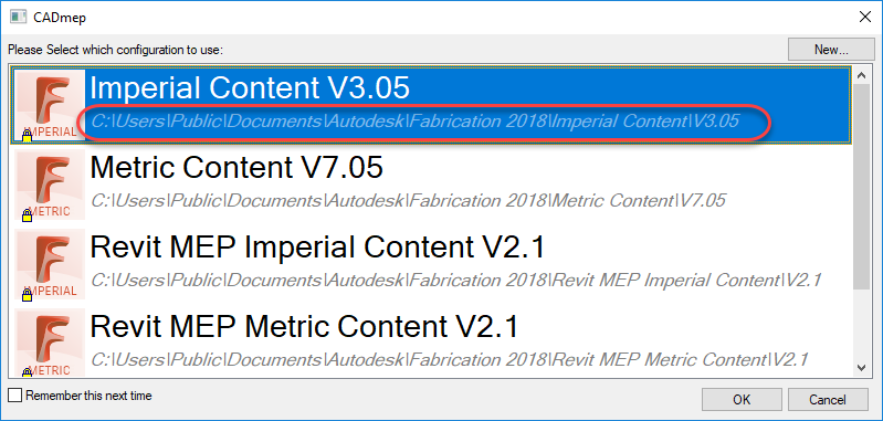
Your Configuration selection dialog shows where the MAP.INI is located.

Here, you can see by default, the SPOOL.INI file is located in the same folder the configuration (MAP.INI file). If you don’t see a SPOOL.INI, you’ve likely never performed spooling or your systems had already been configured. When this location is in a shared network location used by many users, they all read and write from the same SPOOL.INI folder and this can cause conflicts if multiple people are spooling at the same time.


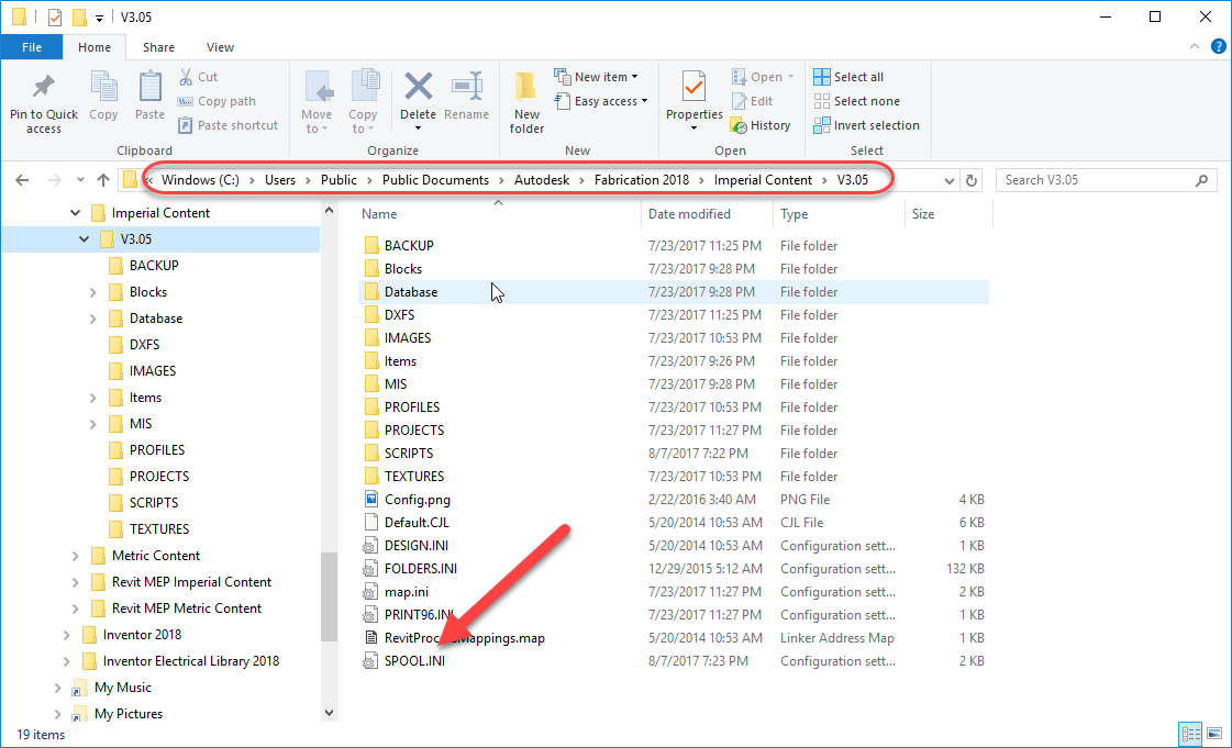
By Default, the SPOOL.INI is created in the same folder as MAP.INI.

Changing the SPOOL.INI location

To change the SPOOL.INI location, you need to edit the registry and create a new entry. Start the Registry Editor by pressing the Windows key on your keyboard and typing “Regedit“. This will call up the Registry editor. You’ll want to navigate to the following location…

HKEY_CURRENT_USER\Software\Autodesk\Fabrication 2018\CADmep

A few things to note….

  1. The HKEY_CURRENT_USER section in the registry is very similar to HKEY_LOCAL_MACHINE. Make sure you edit the HKEY_CURRENT_USER section of the registry as the other location will not work.
  2. The HKEY_CURRENT_USER section in the registry is User specific. Edits here will work for the currently logged in user. If another user logs into Windows on the same computer, this section will need to be edited again for the setting to apply to that user.
  3. This setting is also version specific. Change the “2018” in these examples to the version your you are using. If you are using multiple versions of CADmep, you’ll want to make this change for each version.
  4. This setting is global in scope for the user who’s currently logged into Windows when you make this change. It is NOT specific to the database configuration they are using. When you redirect CADmep to a new location for it’s SPOOL.INI file, it applies for any and all configurations that this user loads in that version of CADmep.
  5. The folder you specify must already exist. It won’t be created for you. You’ll get an error when spooling if this is the case.
  6. The SPOOL.INI does not need to exist, CADmep will make a new one using it’s defaults if there isn’t one already there. If you have one already setup, you can copy it to this location and CADmep will use it.

To change the location of SPOOL.INI location, create a String Value named SpooliniFolder (this is not CaSe SeNsItIvE). A string value will show REG_SZ in the type column. In the data column, you’ll enter the path where you want this particulars user’s SPOOL.INI file. You’ll want to make sure folders are separated by double backslashes or singe forward slashes. The path should also have the ending slashes. Here’s a quick chart of valid and invalid path formats for your reference.

Local Path formatUNC Path FormatValid Path
C:\MySpooling\\MyServer\Share\MySpoolingNo
C:\MySpooling\\\MyServer\Share\MySpooling\No
C:\\MySpooling\\\\MyServer\\Share\\MySpoolingNo
C:\\MySpooling\\\\\\MyServer\\Share\\MySpooling\\Yes
C:/MySpooling//MyServer/Share/MySpoolingNo
C:/MySpooling///MyServer/Share/MySpooling/Yes
C://MySpooling////MyServer//Share//MySpoolingNo
C://MySpooling//////MyServer//Share//MySpooling//No

When you are done, your registry should look like the following image.


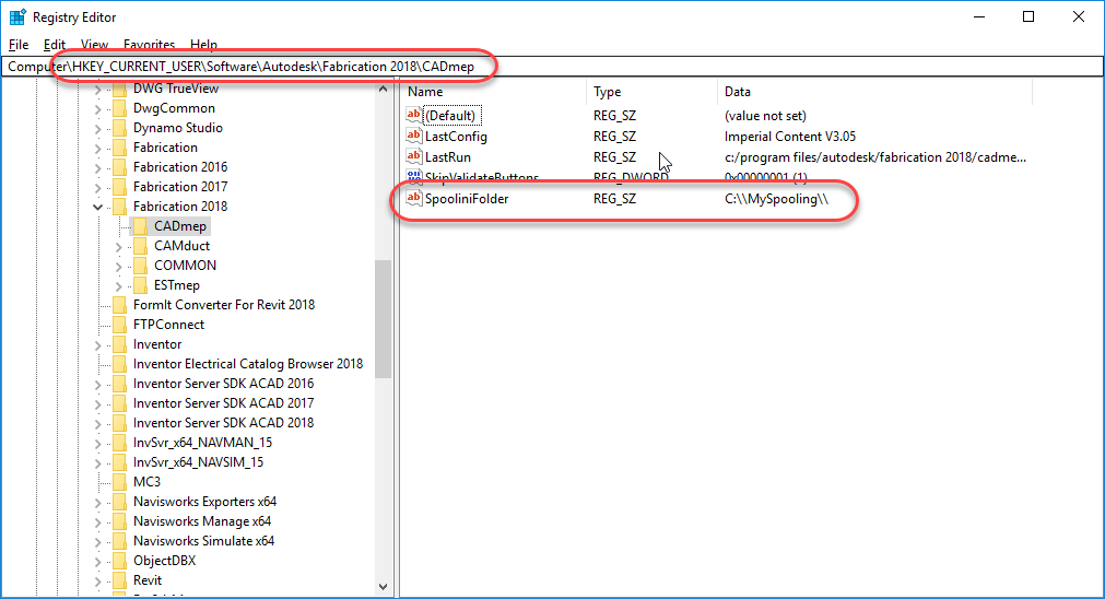
Registry configured to redirect CADmep to a new folder for it’s SPOOL.INI.

Because CADmep read and writes to the SPOOL.INI file each time it spools, this is one of the few settings you can make that take effect immediately without having to restart CADmep. You can see the new folder and SPOOL.INI below after the chages have been made.


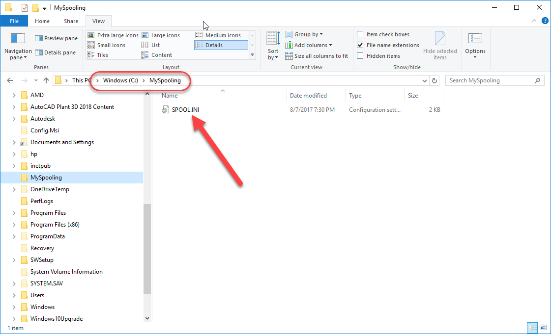
SPOOL.INI is now located in a new folder for the user currently logged into Windows.

Rethink what’s possible

Many of the companies I run into that do not have their MAP.INI file located on a network resource, keep it locally specifically because of issues like the spooling conflict with multiple users sharing the same SPOOL.INI. They often would like to have their MAP.INI are other setting located on a network to maintain consistently in settings and easy of support but don’t, viewing the tradeoff worth it to eliminate the spooling conflicts. If your Fabrication configuration points to a local MAP.INI, you may want to consider the above solution if Spooling conflicts was the reason for your current fabrication configuration setup.

Autodesk Fabrication Resources

I’ve posted a number of Autodesk Fabrication resources for anyone using Autodesk Fabrication CADmep, EDTmep, CAMduct or Fabrication parts in Revit. You can find them using the Resources menu or by following the link here. You can also find this same information on the site XtraCAD.com. In the future, I’ll be compiling and posting additional resources that I’ve collected over the last several years in the course of administering Autodesk Fabrication databases for some large MEP firms.

Fabrication Resources…
  • History of Autodesk Fabrication build numbers for all the versions, service packs and product updates.
  • Pattern/CID Number history lists which Pattern Numbers (CID’s) are supported in which versions of the Fabrication products.
  • Revit Support history lists which Pattern Numbers (CID’s) are supported by which Revit versions.
  • CADmep command history lists which commands where added/removed from the different CADmep versions.
  • AutoLISP function history lists which versions of CADmep support which CADmep specific AutoLISP functions.
  • FabViewer command history lists the commands supported for the FabViewer in each version of Fabrication products.
  • Post Processor history lists which post processors are supported in each version and/or servicepack/update of the Fabrication Products
    • Decoiler/Coil Line Posts (DPL’s)
    • Plasma/Laser/Router/Waterjet Posts (VPL’s)


AutoCAD Performance & RegApps

Slow Drawings?

One of the powerful features of AutoCAD is the ability for applications to built on top of it. Unfortunately,  these applications can often leave remnants of themselves inside your drawings and cause performance issues. One such side effect is the buildup of Registered Applications or RegApps for short. These RegApps are left in the drawing’s Symbol table after entities that contained the XDATA (Extended Entity Data) they used are deleted.

While this can affect any user, this can be very common in the AEC industry as collaboration with external parties and trade partners means you’re typically referencing a lot of files from many sources. I’ve seen cases where a drawing with 50,000 RegApps can take 10 minutes to load and after clearing RegApps, takes merely seconds.

What most people don’t realize is that even though “RegApp” is an option with the PURGE command, using PURGE ALL will NOT remove them. You need to call PURGE separately, with only the REGAPP option.  Click the following ScreenCast recording link to see a demonstration of this…

Example: How to Purge RegApps

  The video shows PURGE ALL and doesn’t list that any RegApps were removed. Purge is then called again, and only the REGAPP option is used which then removes several RegApps. Try it yourself, the drawing used was in the Sample Civil Sheet Set drawings that shipped with AutoCAD 2018.

Problem Keeps Returning?

External References (XREFS) and/or blocks can make the problem difficult to eliminate. You may need to process all Xrefs and block libraries to verify these RegApps aren’t being introduced from those sources. If you’ve used WBLOCK to save a block to disk from a RegApp corrupt drawing, that DWG file also has the issue.

Luckily, Autodesk has a batch utility (free) that will process multiple file/folders, automatically look in sub-folders as well as automatically load any referenced drawings as well.

Click the following ScreenCast link to see the process in action…

Example: CleanupRegApp Utility

Depending on your version of AutoCAD, you can get this utility from the following links..

201832-Bit Program64-Bit ProgramKnowledge Base ArticleRead Me
201732-Bit Program64-Bit ProgramKnowledge Base ArticleRead Me
2015-201632-Bit Program64-Bit ProgramKnowledge Base ArticleRead Me
2013-201432-Bit Program64-Bit ProgramKnowledge Base ArticleRead Me
2010-201232-Bit Program64-Bit ProgramKnowledge Base ArticleRead Me
2008-200932-Bit Program64-Bit ProgramKnowledge Base ArticleRead Me
Schedule Cleanup After Hours

One last benefit if this utility is that it can be called from a DOS window with command like syntax. In a collaborative environment where Xrefs are being updated frequently by others, RegApps can keep getting reintroduced requiring this process to be run frequently. Because you can call this process completely automated from the a DOS prompt, this means you can create a batch file that’s scheduled to be run on a regular basis, even nightly on your drawing library. The following Screen Cast link shows how to call the utility from a DOS command prompt…

Example: DOS Command line