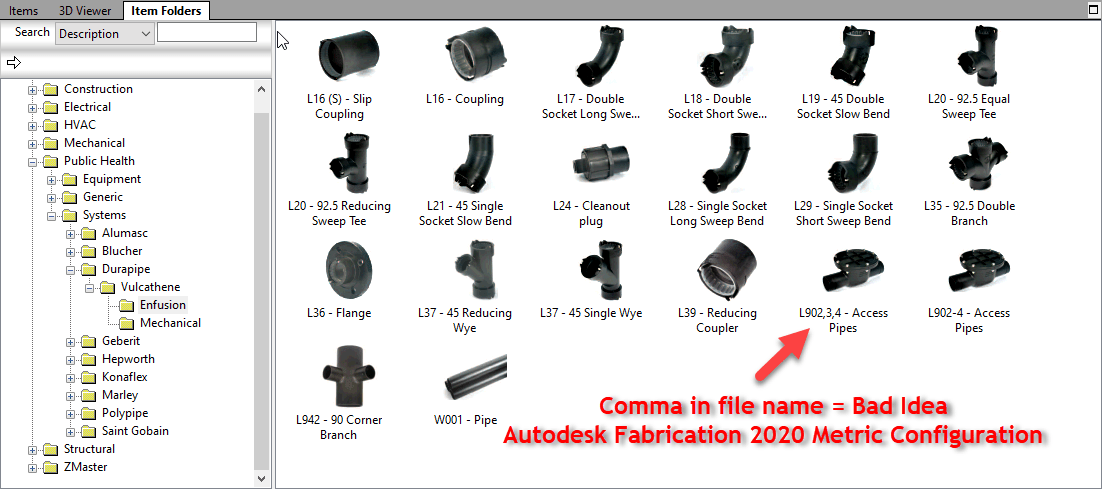
Don’t use Commas (,) in Database Entry Names, ITM File Names, Don’t Use Them Anywhere.
Similar to Best Practice #1 (Don’t use Double Quotes), you should avoid using commas. Commas are the delimiting character in a CSV file. Using a comma can throw off the data columns in data exports that use the CSV file format.
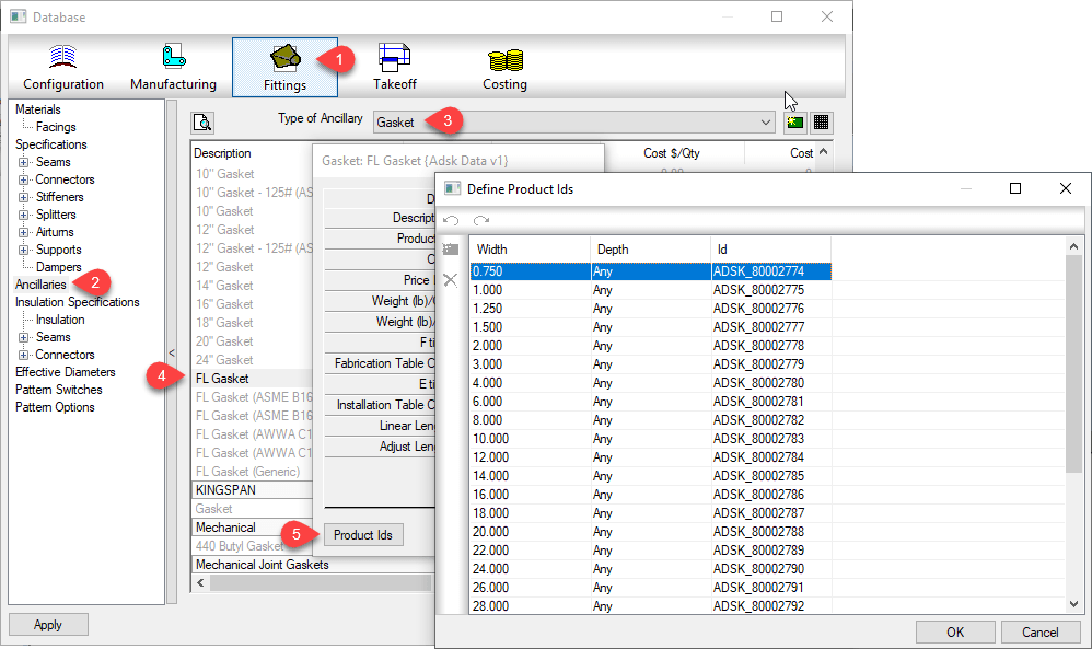
Below, you can see Autodesk let a comma slip into a file name in their Metric Configuration.Yes – Ancillary in Ancillary Kit
In a recent LinkedIn post, the topic of Tolerance Stacking was brought up. I’m not a machine designer, but I’ve spent a lot of my past life in Manufacturing. In that world, the term was used frequently. If the term was used in Construction, it certainly wasn’t when I was listening.
Tolerance Stacking can be described (in my mind) as the accumulation of allowable tolerances to a point where the design is no longer suitable for it’s intended purpose. Errors resulting from Tolerance Stacking are caused by a few things…
Lack of tolerance awareness
Poor annotation and documentation of tolerances
Both of the above
Tolerance Stacking Explained
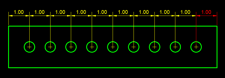
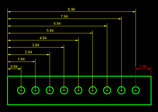
The best way to understand Tolerance Stacking is from a few examples. In our first example, we see a part 10 Units long with 9 holes, equally spaced 1 Unit apart. Take note of the RED dimension on the right.
10 Unit Long Part with 9 Holes Spaced 1 Unit apart
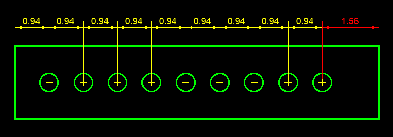
You may have seen parts dimensioned like this. Looks pretty normal. Now lets consider this same part and assume the dimensions have a tolerance of +/- 0.0625 (1/16 Inch). Now lets also assume that all the dimensions are in the negative -0.0625. The following graphic illustrates this condition. Again, notice the RED dimension on the right.
Tolerance Stacking using the an allowed -0.0625 on each dimension.
Is the overall length really have enough tolerance to compensate for the accumulation of those tolerances?
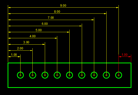
Now lets look at the same part, same tolerances but annotated/documented differently. It’s not as “pretty” and takes up a lot more real estate on your drawing.
Same part as before but dimensioned differently.
But lets look at that same -0.0625 extreme case tolerance in this scenario. Once again, keep an eye on that RED dimension to the right.
Using an alternate annotation approach solves the Tolerance Stacking problem.
This latest example solves the Tolerance Stacking issue by clearly outlining where the tolerances are allowed. In fact, in construction, we’re already doing this. We just don’t call it Tolerance Stacking.
In construction, one of the ways we eliminate Tolerance Stacking is by dimensioning to gridlines and columns. Dimensions in relation to known fixed points minimized Tolerance Stacking.
Are you old enough to remember when rafters were layed out by hand on the job site and cut individually? You would cut one and use it as a template and use that to mark the others. You never installed the template and used the next cut as your template for another. This minimized Tolerance Stacking as well.
Geometric Dimensioning and Tolerancing – GDT
What’s less familiar, is another concept used heavily in automotive and other precision manufacturing. It’s called Geometric Dimensioning & Tolerancing or “GDT” for short.
Traditional linear tolerances have flaws. GDT on the other hand more accurately describes “features” and allowable deviation from the desired location using a more complex form of graphics and symbols.
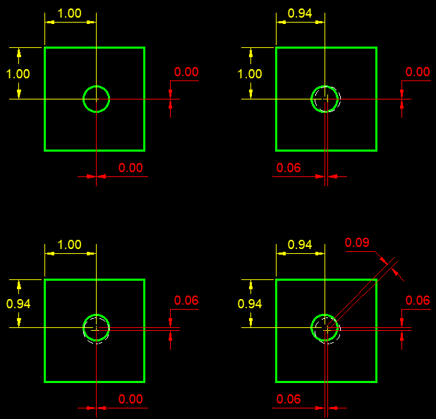
Once again, the best way to explain this is with some illustrations. The following example shows a square part with a hole in the middle. Pay close attention to the RED dimensions.
Top Left – Perfect Part (not real world) Top Right – Hole moved 0.0625 to the right Btm Left – Hole moved 0.0625 up Btm Right – Hole moved 0.0625 in both directions
In this example, you see when the hole is moved to the maximum tolerance in both directions, it’s actually further away from it’s desired position than 0.0625.
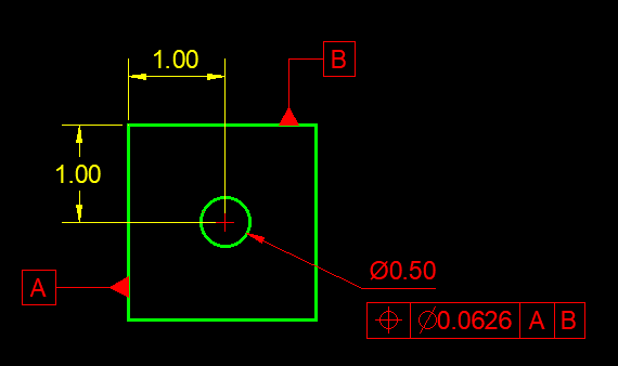
This is where GDT comes in. In this last example, GDT is used to “Describe” the allowable deviation from it’s ideal position.
GDT can more accurately describe tolerances.
There’s actually an ASME Standard for GDT (Y14.5.2) and a full explination of GDT is not only beyond the scope of this blog but my knowledge, There’s a lot of courses out there specifically for this but a good “101” description can be found here.
Given trends in Prefab, Modularization, and Construction becoming more like Manufacturing….Makes you wonder….should there be a “GDT” style of documentation for construction?
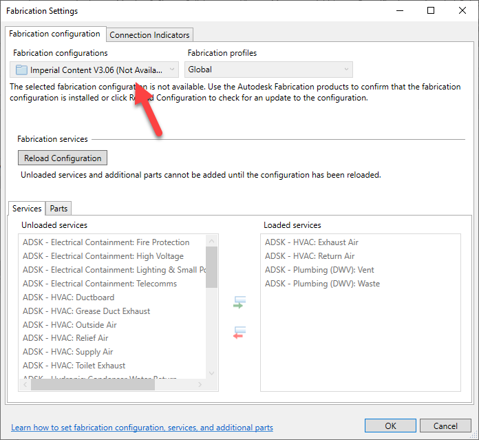
If you’re a user of ESTmep and Revit Fabrication parts, consider yourself warned. I’ve recently had some dialog with an industry colleague and the discussion of Cost data in Revit came up.
We know that that a Revit file which uses Fabrication Parts contains a copy of your Fabrication Configuration (Database). We also know that the Fabrication Extension for Revit now allows you to run reports. Those reports can also report on Cost data. That’s generally a good thing in most firms using ESTmep, exposing that Cost data to Revit users can be very helpful.
Now when you send someone your Revit model, they do NOT have access to your database (Unless you send that to them a well). Without your database, the Fabrication Add-In will not find the reports and the option is grayed out.
You also can’t change the configuration either because the drop down is disabled. They need your database to do anything….maybe.
So this sounds like we’re OK but let me assure you that’s not the case. Your database isn’t “available” to the person who had your Revit file but it is contained within the Revit file itself. And even though the Revit API’s don’t give you access to the costing data, it can be extracted.
I won’t go into details for the sake of security in our industry but rest assured, there is a process where as a user can extract your cost data. This includes being able to figure our your vendor pricing multipliers.
What To Do?
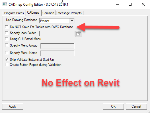
That leaves the question about what to do. Some may be familiar with the option in Edit Configuration that disables the storing of EST tables in DWG files. This has NO effect or control of Revit. Sure would be nice if it did nit that’s not the case.
So there’s really 2 options that I can see….
Remove or Rename the COST.MAP, ETIMES.MAP, FTIMES.MAP and SUPPLIER.MAP tables from your database. These are where labor rates, times and costs are stored. Without these tables,, Revit can not store this information in the model. If you’re previously had a Revit model with this information saved, rename/remove the files and reload your configuration and the data will be removed. The down size is you’ll no longer be able to use ESTmep.
Make a copy of your database without the COST.MAP, ETIMES.MAP, FTIMES.MAP and SUPPLIER.MAP tables and have Revit point to that. Each time you update your Fabrication database, you’ll need to refresh this copy. It’s fairly easy to script this process and have those files removed. The down side is you’ll no longer have access to Cost data in Revit but at least you can keep using ESTmep internally.
If you feel this is unacceptable, please submit a support ticket with Autodesk. The more people that raise the issue, the more likely that it will be addressed in a future release or update. To date, all they told me is the option I’ve outlined are the ONLY way to address the issue.
How many times have you had to reconfigure a system because a server changed? Remapped Drive letters? Links that used UNC paths? It’s downright annoying when IT needs to replace a server and it’s name is different. But it is understandable…systems get old and outdated and need upgrading or replacing.
What I don’t understand is why we use server names at all. Most Ethernet networks use IP addresses to route traffic, not server names. But nobody can ever remember all those numbers. When you type a server name, it pings the DNS server to locate the IP address of that server. Makes sense right.
But we don’t have to use server names…or IP addresses. DNS can be configured with a CNAME Alias (CNAME – Canonical Name). A CNAME Alias is just another human friendly piece of text that’s used to point to another Server Name, IP address or even another CNAME Alias.
What a CNAME Alias do for us?
To understand what a CNAME Alias can do for us, lets take the example of license server. All your client software points to the server name…let’s say is’s something like “P-LA-LIC01“. Now your IT rolls out a new server for licensing…it’s not going to be “P-LA-LIC02“. All your clients need to be updated to the new server name. Depending on the sophistication of your IT and the software they mightbe able to push an update. But more often than not, the local CAD/BIM Manager is left updating clients.
With a CNAME Alias, you could create a nice user friendly name like “ADSK-LICENSE“. All your software would use this name instead of the server name.
This CNAME Alias is setup on your DNS server. Most IT groups won’t give you access but if you know how it works, you can request and have them set it up for you. Just tell them you want a CNAME Alias named “ADSK-LICENSE” that points to “V-LA-LIC01” (ADSK-LICENSE -> V-LA-LIC01). Now when you’re ready to cut you users over to the new license server, have them update the DNS record for the alias to the new server overnight. The next morning, everybody is pointed to the new server, no reconfiguration required.
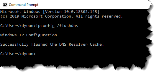
If someone has left on their computer, they may need to reboot to see the changes. In the unlikely event is still doesn’t work, they can open a DOS prompt and flush the DNS cache with the command line “IPCONFIG /FLUSHDNS“
Where does this work?
Just about where ever and ever where you would type a server name. You can make a drive letter using an Alias. You can use an Alias in a UNC path. We can even specify them to point to the IP address of network printer or other equipment.
The only real down side to using a CNAME Alias is that it doesn’t show up when browsing your network, But all things considered, that’s not a bad idea. If it were up to me, no user anywhere would ever know the names of the servers…only the Aliases. I really don’t know why this trick isn’t used more often. IT uses it for their own purposes, it just rarely gets implemented to affect the users. Using this approach, I’ve migrated hundreds of users in multiple locations to new servers with a 3 second DNS update in the evening. I suggest you give it a try.
If you’re using 2017 or older Autodesk products, your software may stop working on June 15th, 2019. Newer versions will continue to work but may have intermittent issues with any of their cloud related services. Exact services and product versions vary.
Many products and services use Transport Layer Security (TLS) 1.0/1.1. Due to known vulnerabilities, on June 15, 2019, Autodesk will be updating their systems to no longer support this protocol. This service is what’s used for Autodesk to determine your “Identity” when providing access to your products and services.
You can read more about the affected products and versions here. This article is specific to which older products will stop working completely. It does not cover newer products that have services which may stop working.
Newer products (2018-2020) Not mentioned in the Autodesk articles are also affected subject to the following….
Ancillary related services and newer products have their own security updates
Access to core product is Not an issue
Ancillary cloud connected services May be affected such as…
Revit Cloud Worksharing
Personal Accelerator (PAC) for Revit Cloud Worksharing
Communicator
Energy Analysis
Dynamo Package Search/Upload
P&ID Modeler
Licensing type of product does NOT matter
Most products have updates available however there are a few that do not. Autodesk Fabrication products in version 2014 or 2015 do not have updates. So unless you’re using those version with a Single User Subscription, you don’t need to worry. If you are using a product that does not have an update, you will need to upgrade to continue working.
Back in the day, I briefly worked for an Autodesk reseller. This particular reseller was classified as an “Education Reseller”. In short, this meant they were one of a few resellers that sold Autodesk products into the educational market (high schools, universities etc.).
As you can imagine, a school would likely have most of not all the products. Back then, Autodesk provided a complete list of all the products and their recommended install order. Fast forward to today, they’ve either gotten incredibly lazy or in all their massive layoffs over the years, the domain knowledge is gone. I suspect both.
Autodesk’s Recommendation
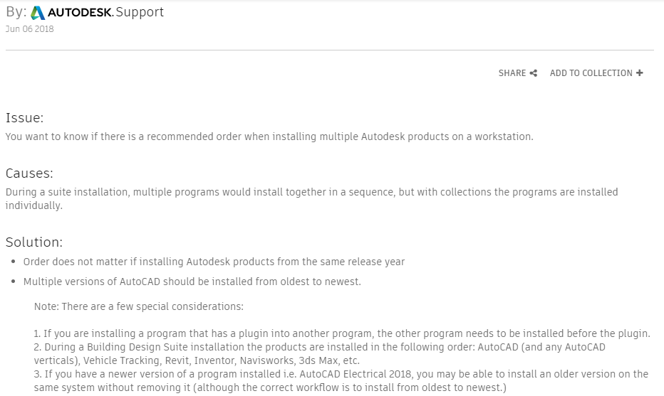
Take a look at Autodesk’s current recommended install order from this link. which was last updated 6/6/2018 at the time of this writing. In the event the link changes, here’s what they say…
What’s wrong is that they tell you within the same product year, the install order doesn’t matter. This is outright false for many reasons. They try to note a couple “exceptions” stating that if there’s any add-ins, the base product should be installed first. But which products have add-ins to what other products?
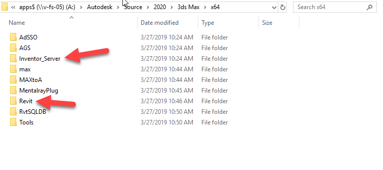
CADmep is obviously running on top of AutoCAD so AutoCAD should be installed first. That seems obvious. But Navis also installs Exporters depending which products it finds and it doesn’t always show up in an Add-ins tab. So this is less obvious. Buy there’s also other dependencies that are even more obscure. Should you install Revit or Inventor? Should either go before or after 3ds Max? This is less obvious to most users.
This is really why someone would ask that question. It’s a real dis-service then to start out telling them it doesn’t matter. In fact, it matters most of the time, and it doesn’t matter as the “Special consideration”.
Determining The Real Install Order
There’s a few ways to handle this. If you’ve been around a while and had one of the old “Design Suites”, install in the same order as the Design Suite did. But note that this did change between product years and types of Suites. Plant Deign Suite 2013 for instance installed Autodesk before Revit where as Building Design Suite 2016 installed Revit before AutoCAD.
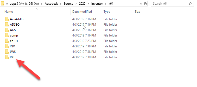
One of the other ways is to look at the install media folders to see if you can find any dependencies. Take for example 3ds Max. Look in the x86 or x64 folders and you’ll see references to Revit and Inventor.
This means we should install Revit and Inventor before installing 3ds Max. But what if we’re using both Inventor and Revit? Which of those goes first?
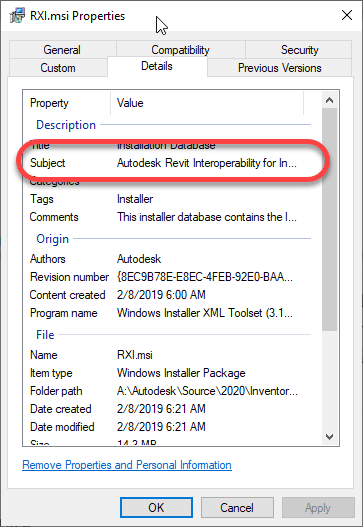
You’ll see the RXI folder in the install files. Hard to tell what it is. When you drill into the folder, there’s just a single MSI. If you right-click on it and select Properties and do to the Details tab, you can see it’s Revit Interoperability for Revit. Other folders deeper in the structure also confirm this by their naming,
Based on this findings, it suggests installing Revit first so Inventor can see it and install the Interoperability tools.
Here’s My Order
So, if you’re an Autodesk Fabrication user, here’s what I typically do (and why)….
Revit(doesn’t seem to depend on anything else)
AutoCAD(I can’t find a dependency for AutoCAD. But anything with an Object Enabler will want it here and it’s a core product so as a matter of safety, I install it early just in case)
AutoCAD based Verticals like MEP, Arch, etc.(These use AutoCAD as its core. I’ve not checked dependencies between verticals but it’s likely safe to install them in any order. I usually do Arch first if I’m going to include it as MEP is built on top of Arch but it’s really not needed as MEP installs what it needs)
Inventor(because of the Revit dependency covered earlier)
3ds Max (because of the Revit/Inventor dependencies)
Navis – Freedom/Simulate/Manage(Navis exporters only install for products already installed so we install this toward the end)
Fabrication CADmep(allows CADmep Object Enablers to install for Acad, Navis, etc.)
Fabrication – EST/CAM/etc.(order doesn’t matter)
If there’s anything on the list you don’t use, just skip it. If you happen to install Navis before some of the dependent products, just use “Add/Remove Programs” in Windows Control Panel to modify the install to include new exporters or download the Exporter installs separately from Autodesk’s web site.
Don’t use Ancillaries with Breakpoints inside an Ancillary Kit.
Ancillaries are virtual items you can add to your Fabrication configuration. ESTmep users use Ancillaries to help quantify cost and labor. Material quantification for purchasing and/or fabrication is another use for Ancillaries. These are virtual items because they typically don’t affect modeling or coordination. They aren’t even typically drawn yet they are critical to your fabrication as a purchased, fabricated or installed item.
Database view of an Ancillary entry
At times, you many need multiple Ancillaries associated with an item. However the fabrication software typically only allows you to assign a single ancillary to an item or database entry like a connector. For this reason, Autodesk Fabrication includes a type of entry called an “Ancillary Kit” in which you place multiple Ancillaries.
These Ancillary Kits are where you can group multiple Ancillaries that are often used together. A Bolt, Nut and Washers are a good example of an Ancillary Kit.
Database view of an Ancillary Kit entry
Ancillary / Kit Breakpoints
Often, Ancillary items are defined by the size of the item they are associated with. As an example, a flange gasket would be different depending on the type and size of flange it’s used with. You can configure an Ancillary to have Breakpoints to reference a different parts depending on the size of the item the Ancillary is associated with.
Database view of an Ancillary with Breakpoints
Just like Ancillariess, an Ancillary Kit can also have Breakpoints. Using a flange as our example again, depending on the type and size of a flange, or what it’s connecting to (another flange, valve, pump) it can have different bolt/nut sizes and quantities. You would manage this using an Ancillary Kit with Breakpoints.
Database view of an Ancillary Kit with Breakpoints
Nested Breakpoints
If you watched the example images closely, you can see Autodesk’s own database breaks this Best Practice rule. The rule is to never add Ancillaries that use Breakpoints to an Ancillary Kit. Here’s how to keep that straight…
Yes – Ancillary in Ancillary Kit
No – Ancillary w/Breakpoints in Ancillary Kit
Yes – Ancillary in Ancillary Kit with breakpoints
No – Ancillary w/Breakpoints in Ancillary Kit w/Breakpoints
I’ve not tested Autodesk’s configuration for reporting accuracy. I have enough work managing my own fabrication configuration. However I did create a sample of my own and submitted to Autodesk support. After demonstrating inconsistent results with my sample, their recommended guidance was not to use Ancillaries with Breakpoints in an Ancillary Kit.
Based on testing in other data sets, I would say this is sound advice. Even if you can get it to work, the setup and configuration is less intuitive and confusing. Your Ancillary Kit can reference different Ancillary types using different Breakpoint criteria. The Ancillary Kit could also have conflicting Breakpoint criteria (e.g. Length x Width vs Diameter) compared to the Ancillary.
Keeping this Best Practice can create more Ancillary entries as well as make building Ancillary Kits a little more time consuming. But the results will be more predictable and what’s really happening in your configuration will be more obvious and less obscure. Even where Breakpointed Ancillaries do function within an Ancillary Kit, it’s advised to avoid this where possible.
Use the Same Version of software to Admin your Database
Consistently use the same version of software for all administration work. You can draw/model/estimate/etc using any version. Just make sure your users don’t have administrative permissions on their login. But for administering your database, always use the same version. Here’s why…
You can work in multiple versions of CADmep, ESTmep, CAMduct and even Revit (w/Fabrication Parts) using the same database configuration. In other words, the configuration itself is “Version Agnostic“.
For Revit Fabrication Parts, database compatibility starts with version 2016. The other Fabrication products like CADmep, ESTmep and CAMduct, compatibility goes back to at least the version prior to 2013, before Autodesk acquired the software.
What’s the problem?
You often get new functionality in newer versions of software. Versions of the software that require new data, automatically adds the new data to the database tables. When you only Use older versions of the software without administrative permissions, it ignores that extra data when it encounters it. This is why old versions work with configurations edited with newer versions,
When you try to use an older version to Administer your database, it rewrites those tables but doesn’t see the added data so it gets overwritten. This is why you should stick to the same version when editing your database.
You do not have to use the latest version to maintain your database. You can continue to use an older version for administration. Just don’t use a newer version then go back to the old. You’re perfectly fine to stick with an older version. You just won’t be able to take advantage of new features that rely on added data the new version offers. When you are ready to start using a newer version for Administration, you can make that change anytime but you should also stop using the older versions for administration.
Let’s Demonstrate the Issue
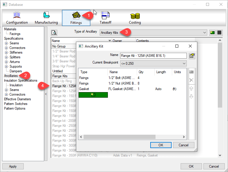
You can watch the video at the end of this article to see an example. In 2019 Autodesk added a new Connector setting for “Connector Matching”. We won’t go into what this does here but you can see in the following image the difference in the right-click menu of connectors.
Fabrication 2019 Added ‘Connector Matching‘
When you watch the video, you’ll see me switch between 2 different versions of ESTmep. I could use any product but ESTmep lets me quickly open and close a database so I can move between versions quickly.
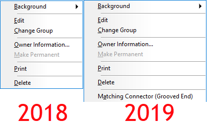
If you look at the configuration icons, you can see which version of software is being used. ESTmep 2019 has all BLUE icons. You can see ESTmep 2018 uses RED icons except the one BLUE 2019 configuration.
ESTmep 2018 has RED Configuration Icons, 2019 uses BLUE Icons
The video starts with “A Test Config” loaded in ESTmep 2019. I select one of the Connectors and change its ‘Connector Matching‘ value. Next, I exit and go back into the same configuration again in 2019 to show the value remains the same. At this point, everything is working as planned.
After exiting the database in 2019, I then switch to ESTmep 2018 and load the same “A Test Config” database. I make a copy of a completely different connector. This is where the problem starts. ESTmep 2018 has no knowledge of this ‘Connector Matching‘ data. Your “Connector Matching” data is over written as soon as ESTmep writes the Connector tables using the format it knows.
Finally, I go back into ESTmep 2019 and verify the data is gone. The default value for the Grooved Coupling’s “Connector Matching” data changes back to “Same“.
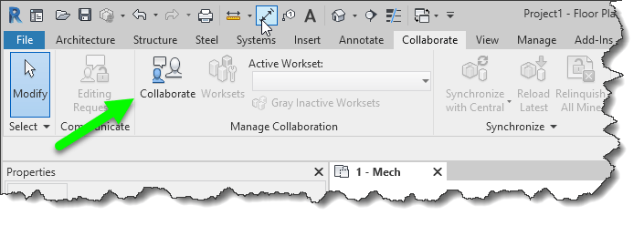
If you use BIM360 Design (formerly “Collaboration for Revit” a.k.a. C4R) along with the Autodesk Desktop Connector, you should be aware of a common mistake that can lead to data loss.
BIM360 Design or C4R as the older version is called, is used to store Revit models in the cloud on Autodesk’s BIM360 platform. BIM360 Design using the BIM360 Docs platform as storage platform. C4R on the other hand uses the older BIM360 Teamfor storage of the Revit models.
While you could (can) upload your Revit models via the web interface to either storage platform, Revit would not see these files. They needed to be enabled for Collaboration and uploaded through Revit. This process made changes to the Revit files which enabled collaboration from BIM360 Design/C4R.
BIM360 Design/C4R collaboration is enabled and files uploaded using the Collaborate ribbon in Revit.
while Revit models need to be uploaded this way, there was no other way to upload other files types besides the web interface. Even if you did upload AutoCAD, IFC, Navis or other files types that Revit can link, there was no way to link these files into Revit from the BIM360 platforms. If you linked them from your server, the other members of your team without access to your server would not have access.
Autodesk Desktop Connector was created for this purpose. While you can’t link a non Revit file type into Revit directly from BIM360, you can use the Autodesk Desktop Connector to sync those other files types locally to your computer. Any other team members also using the Autodesk Desktop Connector would then also have access to those same files and the links would be identical.
What’s the problem?
The common problem that comes up when using BIM360 Design/C4R along with the desktop connector is Autodesk’s unfortunate choice in using the same icon for both products.
Depending where you see the icon, you get different results. If you click the one that references BIM360 collaboration services you’re good. If you click the one that references the Autodesk Desktop Connector, bad things can happen.
When a file is enabled for Collaboration and you open it through the Autodesk Desktop Connector, Collaboration is disabled and the file is configured as a local file or central file like you’d typically use of a file server. When this happens, the file is seen as being different and will not sync back to the BIM360 platform.
What this means then if that you have two different version of the file. One stored locally from the Autodesk Desktop Connector and another cached locally when opened from BIM360 Collaboration service (BIM360 Design / C4R) When you look at BIM360 Docs or BIM360 Team portals, you only see one version.
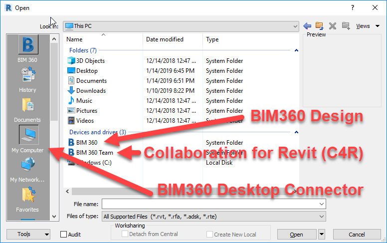
How do I know I’m using the correct Icon to open my Revit file?
Depending on the particular versions of Revit and their update versions, your install of Revit may appear different but the underlying concepts are the same. For these images, Revit 2018.3.2 and 2019.1 were used.
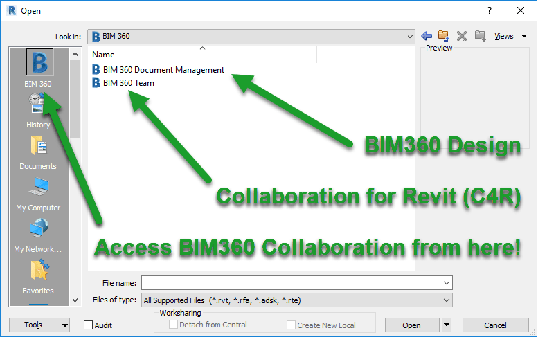
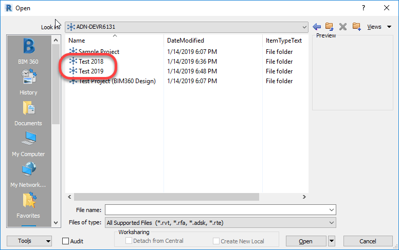
When opening a Revit model from 2018, you’ll see the “B” shortcut in the left. This is the proper way to open BIM360 Design/C4R enabled files. BIM360 Design and/or C4R sites will be listed depending if you have been given access to projects within those sites that use 2018 version of Revit.
Revit 2018 Open Dialog when accessing BIM360 Collaboration models.
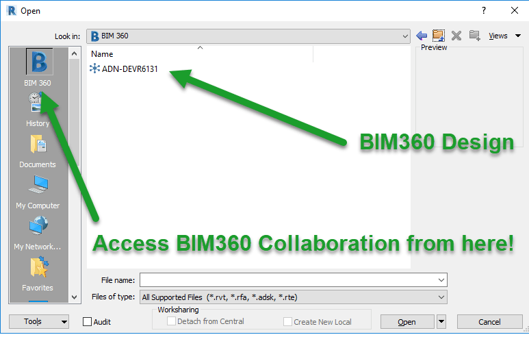
When opening a Revit model from 2019, you’ll also see the “B” shortcut in the left. The same as with 2018 versions, this is the proper way to open BIM360 Design enabled files. BIM360 Design only will be listed because 2019 doesn’t use BIM360 Team/C4R. If nothing is displayed here, you may not have been given access to projects within those sites that use the 2019 version of Revit.
Revit 2018 Open Dialog when accessing BIM360 Collaboration models.
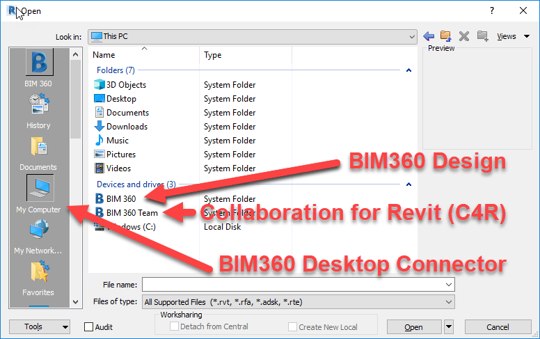
The other place you may see the BIM360 icon is from My Computer or other shortcuts that look at your local system. The following image shows 2018 when using the incorrect shortcut because it instead points to the Autodesk Desktop Connector drive on your computer.
Revit 2018 Open Dialog when accessing the Autodesk Desktop Connector Drive
And once again, 2019 versions of Revit are similar. On clue is that here, even though 2019 doesn’t support C4R, they are listed here. This is because you’re not accessing via Revit’s collaboration tools, you’re simply accessing a special local drive on your computer that’s syncing everything in the BIM360 platform completely independent of Revit.
Revit 2019 Open Dialog when accessing the Autodesk Desktop Connector Drive
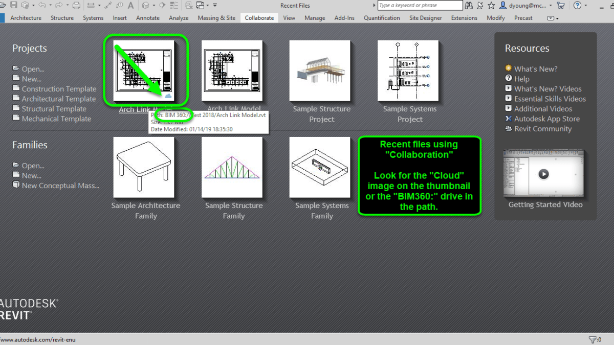
More clues when opening Models from the Recent Files List
If you’re trying to open Revit models using the Recent Files list, there’s a few subtle clues that tell you if you’re opening a collaboration enabled BIM360 model or simply opening a model from the Autodesk Desktop Connector drive.
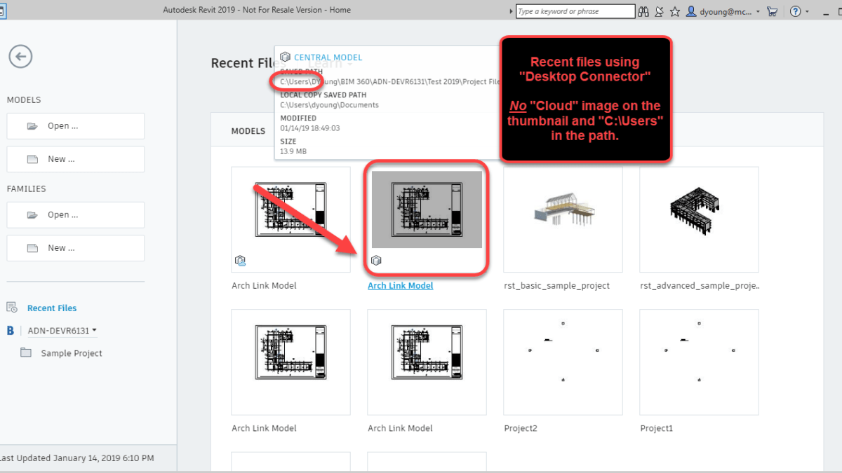
The following image shows Revit 2018 with a BIM360 Design/C4R model correctly. Notice the drive letter in the path as well as the “Cloud” image in the thumbnail.
Revit 2018 with a Recent File that uses BIM360 Collaboration
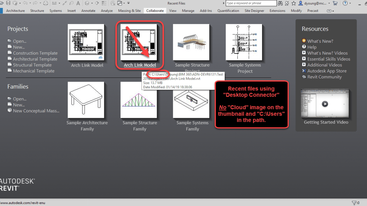
The following image shows Revit 2018 with a Recent File that was accessed incorrectly from the Autodesk Desktop Connector. Notice the path will point to your Users folder on your computer and there’s no “Cloud” image on the thumbnail.
Revit 2018 with a Recent File that uses Autodesk Desktop Connector
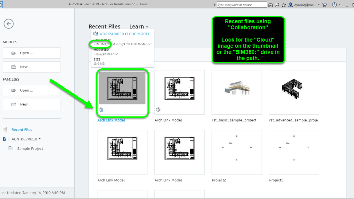
Similar to 2018 but formatted differently, Revit 2019 displays the same details in it’s Recent Files. The following image is 2019 showing a recent file opened correctly through BIM360 Collaboration tools.
Revit 2019 with a Recent File that uses BIM360 Collaboration
And one more image below that shows a recent model opened incorrectly from the Autodesk Desktop Connector.
Revit 2019 with a Recent File that uses Autodesk Desktop Connector
Additional Clues
Looking at some of those subtle options can easily be overlooked or forgotten. Especially in the daily stress of production and deadlines. There are a few more obvious clues that can tell you if you’re opening your Revit models correctly.
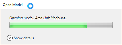
For starters, when you open a BIM360 Design or C4R model properly in Revit, you’ll see a nice status dialog indicating that the files is being opened and sync’d locally.
Opening BIM360 Models Properly Displays A Status Dialog
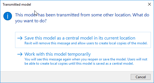
On the other hand, there’s a major red flag when you open the files incorrectly though the Autodesk Desktop Connector. When you open the files incorrectly, you’re prompted to work on the model temporarily or save it locally as a Central Model. If you see this dialog, you know you opened the file incorrectly and should click the Cancel button.
Revit Model Opened Incorrectly from the Autodesk Desktop Connector
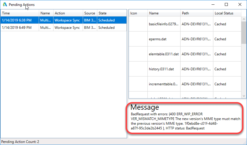
If for some reason you or another user did open the file incorrectly, you can use the Autodesk Desktop Connector icon in the Windows System tray to review the pending actions. There will likely be warnings when reviewing the connector’s syncing status tasks. Note however that that lack of pending tasks with errors does not mean a file can’t been opened incorrectly. Any number of other actions could have overwritten the local copy or cleared those actions.
Autodesk Desktop Connector Pending Actions With Errors
Another subtle clue is that if you look at the collaboration hubs and you see multiple projects that use different versions of Revit between them, you know you’re opening the models incorrectly. The Autodesk Desktop Connector display all projects, regardless of Revit version being used because it;s independent of Revit. When opening files correctly for BIM360 collaboration, Revit 2018 will only see 2018 project versions and Revit 2019 will only see 2019 project versions.
Again, if you don’t see differently projects that use different Revit versions, that does not mean you’re opening them properly. You merely may have been granted to projects of only one Revit version. But if you do see multiple projects you know are using different versions of Revit, it;s a sure sign you’re opening the files wrong.
Two Projects Using Different Versions of Revit Listed Together is a Red Flag
Best To Avoid Using The Dropdown
The last word of warning is with using the drop down list in the Open dialog. Depending when and how you’ve accessed Models, neither BIM360 icon may be present, one or the other may be present, or both BIM360 icons may be present. Because they have no description, its hard to tell wich does which.
The following image shows the Dropdown list expended with both BIM360 icons displayed. One will take you to the proper BIM360 collaboration tools and the other, incorrectly to the Autodesk Desktop Connector.
BIM360 Collaboration and Autodesk Desktop Connector Icons Look Similar.
Because of this very subtle difference, it’s likely a best practice to not use them ever. If they don’t show up on your system, don’t worry. They typically won’t display until you’ve first accessed the corresponding My Computer or BIM360 shortcuts on the left side of the dialog.
Disclaimer: I’m not a professional coder. Just a good hack, script kiddie, amateur, whatever you want to call me. But I’ve been doing it for a while and I tend to be good at finding ways to make things less error prone. I also pickup tricks from industry peers who humble me with their ability.
If you aren’t a professional programmer, you’ve likely never been told either. So I’m telling you as its helped me and I’m sure it’ll help you too if you’re an amateur like me.
This works regardless of language. Whether you code in Visual Basic, AutoLISP, Java, C# or any other language the concepts are the same but the syntax will be different. For this reason, I’ll use pseudo code…that is, syntax that isn’t any particular language but uses terms obvious to describe what’s going on.
The Issue with Strings (Text)
A common activity in any programming is reading text, often called String data types. You read the value from somewhere else like a property or have the user type the data. You then need to test the data in a conditional statement to see if the data is valid. You may also be testing to see which action to take depending on what was typed.
The problem when doing this is you don’t always know the case used when typing. Most conditional testing on string data is CaSe SeNsItIvE. Take the following examples….
MyValue = "Elephant"
if MyValue = "Elephant" then
  MessageBox "Yes - There's an Elephant in the room"
end if
This code works because the case of the text strings is identical. But what about this….
MyValue = "elephant"
if MyValue = "Elephant" then
  MessageBox "Yes - There's an Elephant in the room"
end if
In the above code, the test fails because the “E” in “Elephant” is now lower case. This is very simple to solve and is obvious once it’s pointed out.
To resolve this, when you test a String value, use code to force the value to either UPPER (or lower) case and test against that. Now look at the following code…
MyValue = "Elephant"
if Upper(MyValue) = "ELEPHANT" then
  MessageBox "Yes - There's an Elephant in the room"
end if
…or this example….
MyValue = "Elephant"
if Lower(MyValue) = "elephant" then
  MessageBox "Yes - There's an Elephant in the room"
end if
In either of these examples, we take the value we want to test, force it’s case one way or the other and test against that case. Now it doesn’t matter what case is typed by a user or returned when reading a value, the test is now essentially inoculated from case differences by forcing it one direction or the other.
A Less Obvious (but related) Tip
Another common mistake I see people do is not use this technique when they know the software better. For example, lets say you wanted to retrieve the type of AutoCAD object and noticed that AutoCAD ALWAYS returns the name in mixed case….”Line”.
It’s common for less experienced programmers but very smart and observant coders to ignore the tip I just suggested. I’d advise you to NOT do that…always use a forced case when testing text strings. Even when you’re sure the value you are reading and testing is always a particular way.
Why? What happens if…that pesky if…AutoCAD or whatever you are using changes? Autodesk sees a lot of programmers…maybe they overhaul AutoCAD code and object types are now returned upper or lower or a mix? You’ve now put in the hands of someone else if your program will break in the future. As unlikely as it seems, it’ll eventually happen. The key to writing resilient code is tricks like this. Think of it as a coder’s version of “Defensive Driving”. Anticipating future inconsistencies and planning for them makes your code more resilient and less likely to break on your next upgrade.