Autodesk Fabrication: Connector Matching – The Feature Nobody Knows About & Why You Should Use It.

Do you know what ‘Connector Matching’ is as it relates to Autodesk Fabrication? It’s been in the product since the 2020 release. Yet most people I run into have no clue what it is.

There’s a good reason for that. It’s hidden from view. That is to say, there’s a good reason you don’ know about it. There’s no good reason it’s hidden from you besides Autodesk is pretty slopping (lazy?) when it comes to product design in recent years.


What is Connector Matching?

Connector Matching only works in Revit w/Fabrication Parts. If you’re not using Revit, you need not worry about it but setting it up won’t cause any issues either. It’s designed to place a matching connector on pipe after you cut in a fitting when modeling in Revit. CADmep, ESTmep and CAMduct will simply ignore the settings.

As an example, if you’re drawing a welded piping system and want to break it with a Grooved coupling, Connector Matching places the proper grooved connector on the end of the pipe when the Coupling is placed. This helps us build a system with Welded Pipe Spools that’s assembled in the field with Grooved Couplings…a very common activity in mechanical construction.

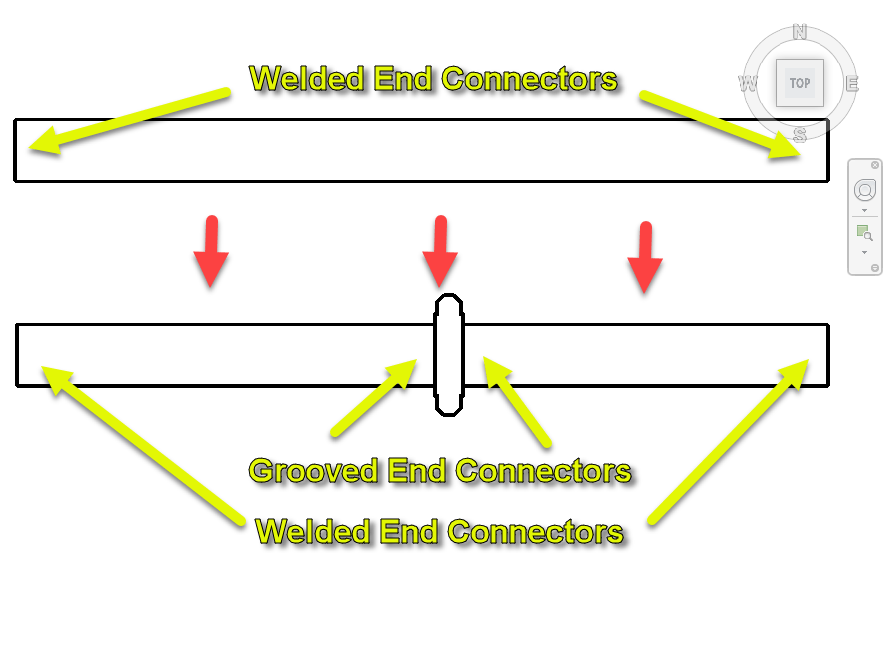
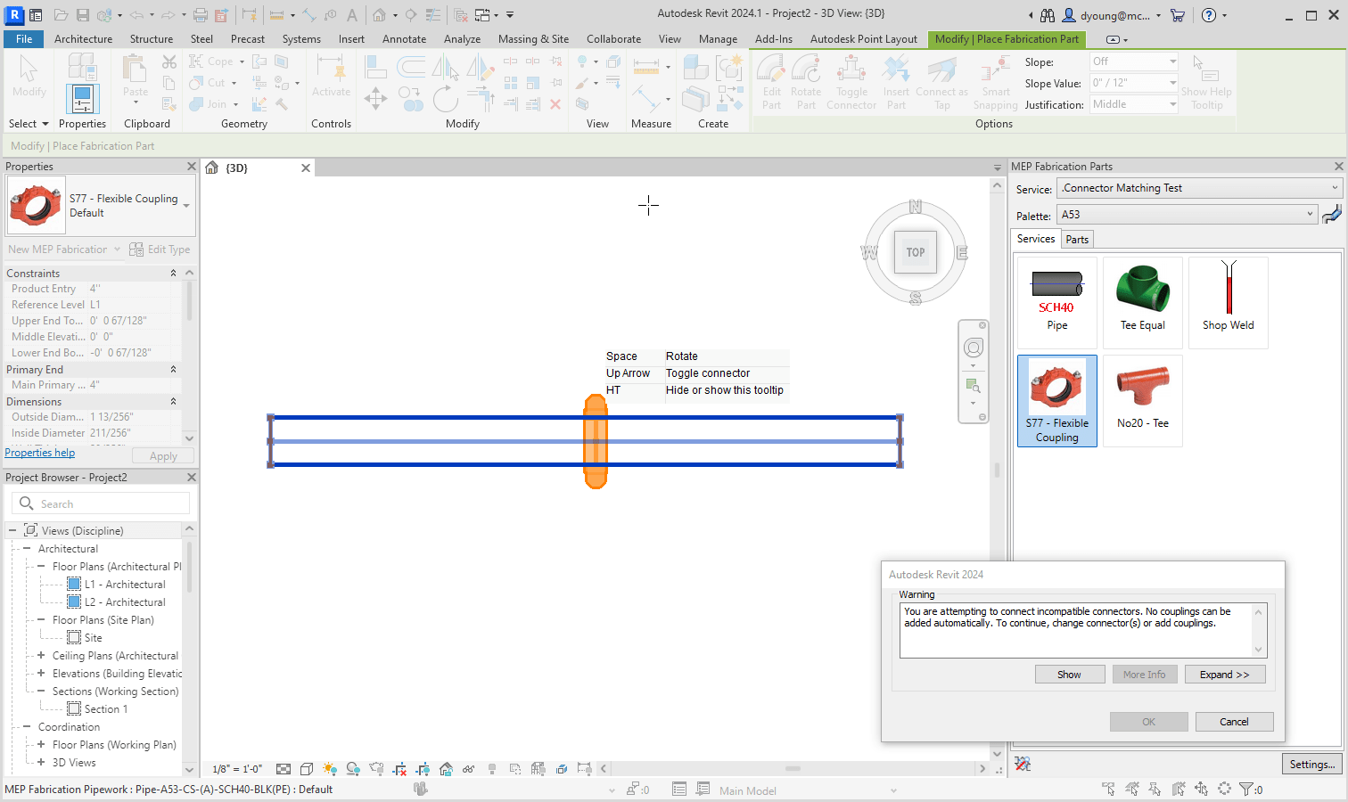
When Connector Matching isn’t configured, you’ll have issues cutting in things like a Grooved Coupling into a Pipe that’s part of a welded system.


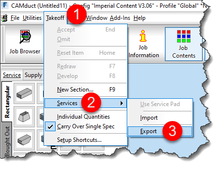
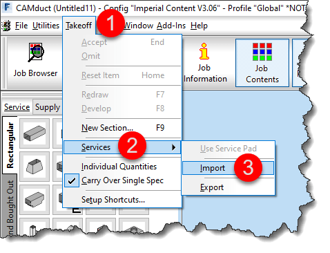
Configuring Connector Matching

The reason many don’t know about connector matching is because it’s hidden. None of the 3 views (Manufacturing, Costing & Drawing) display this option.

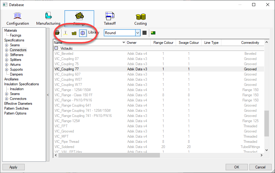
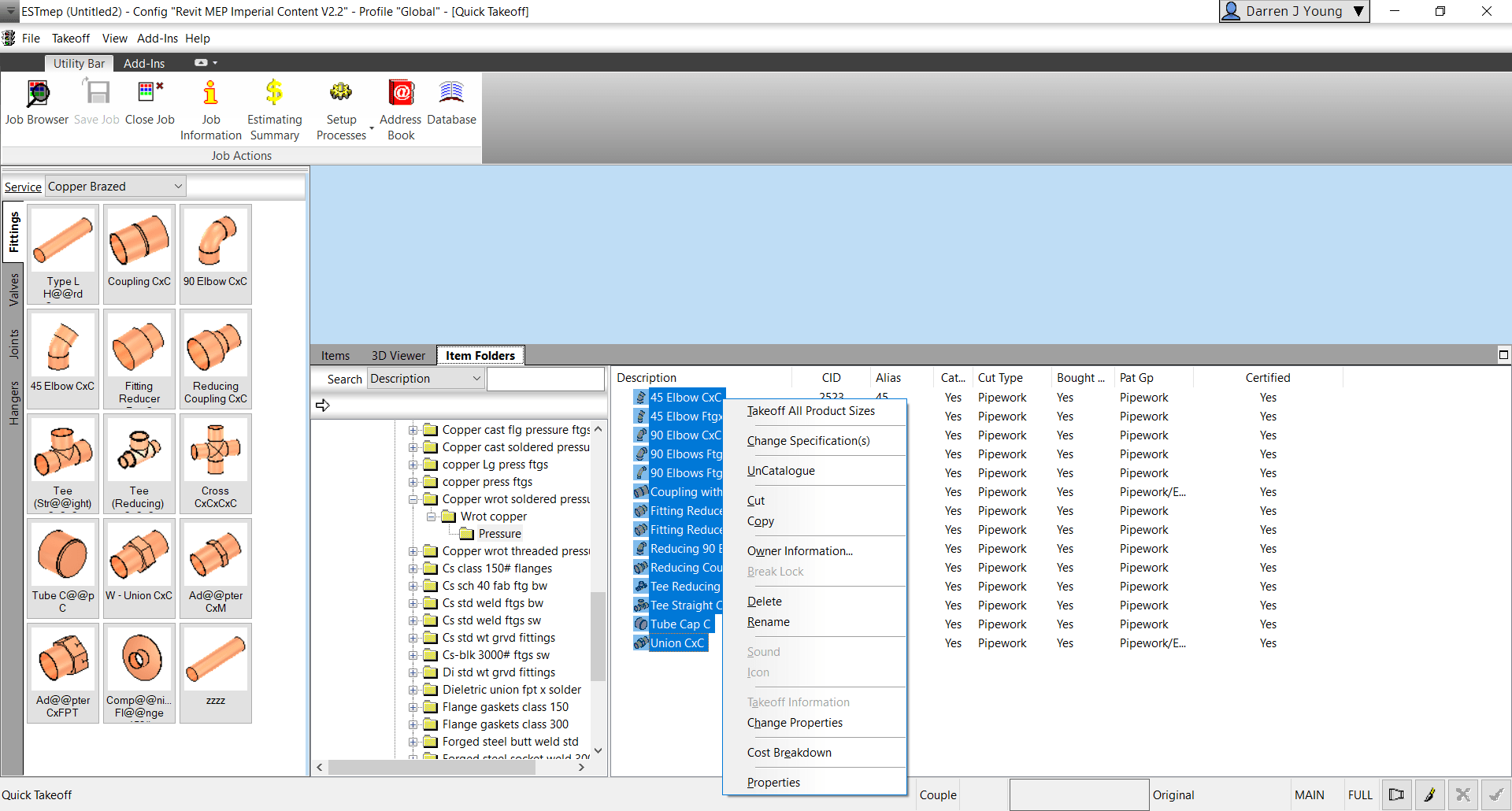
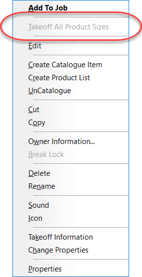
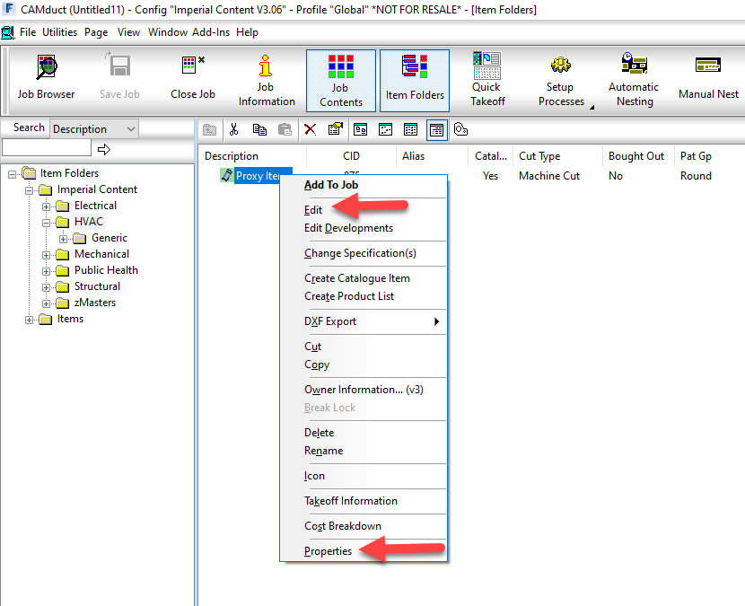
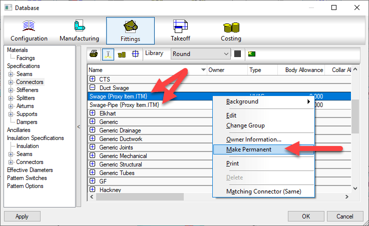
To set Connector Matching, you Right-Click on a connector that’s configured for the Item you need to match. In this case, it’s a Victaulic 77 Coupling.

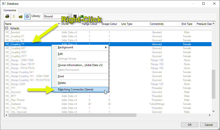
You can see the Matching Connector is set to “Same” by default. That’s certainly not what we need so select that menu option.

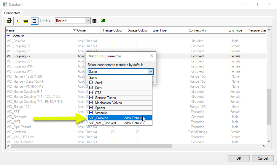
You can see now the Matching Connector is set to a Grooved Connector. So every time an Item with the “VIC_Coupling 77” connector is cut into a piece of pipe, the pipe will get a “VIC_Groove” connector.


Added Configuration to Make it Work

Above, you set the matching connector. Unfortunately, that’s not enough. There’s some added configuration to verify to ensure that it works.

One of the requirements of Connector Matching is to make sure the Pipe’s Connectors are NOT locked and defaulted to the connectors they should use. In other words, ‘Set’ but not ‘Locked’.

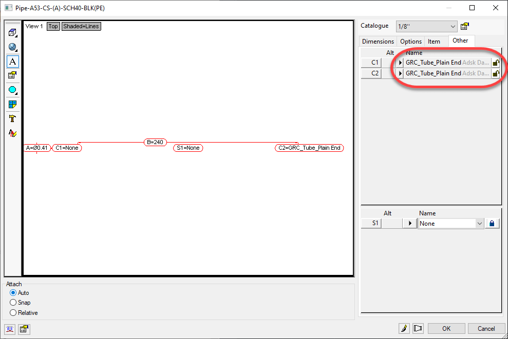
Here’s what your Pipe ITM most likely looks like…

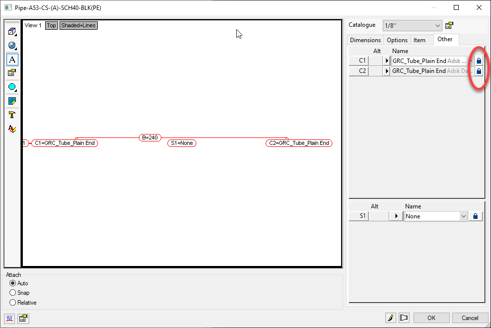
What I recommend here is, Unlocking only 1 of the Connectors and Clicking OK. After you do that, go back and edit the ITM again and take a look at the Connectors.

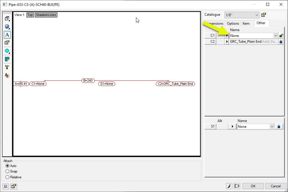
You can see here that after Unlocking one of the Connectors and Clicking OK, going back to edit the ITM the Connector changed to “None”. This is a tell tale sign that there’s yet another thing you have to change to make it work.

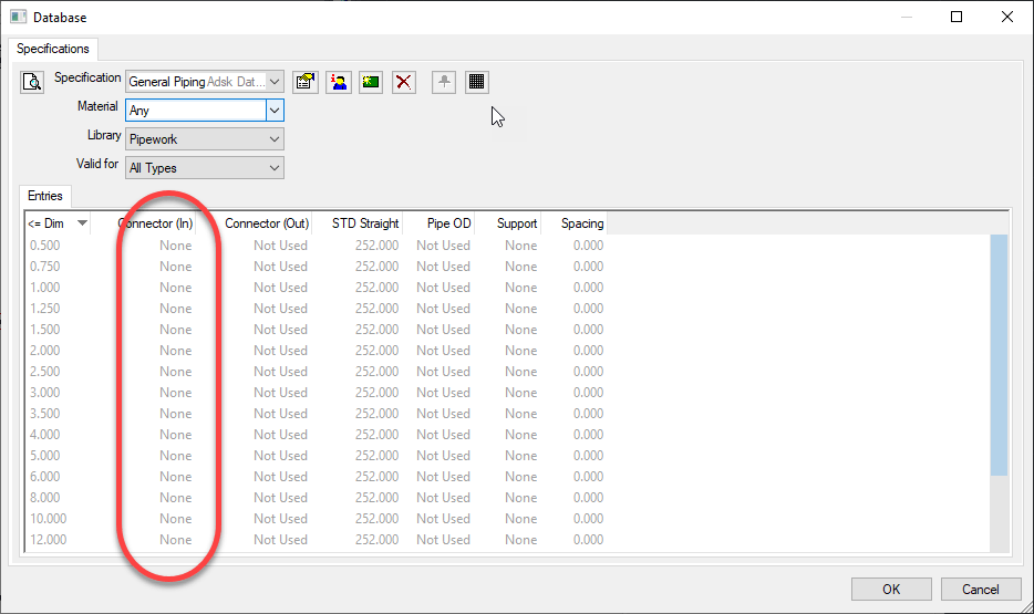
In some Configurations, people have the Specification set to drive the Connectors. This is most commonly done for Sheetmetal but you see it in Piping as well. In the following image, the Piping Specification is configured to set the Connector to “None”.

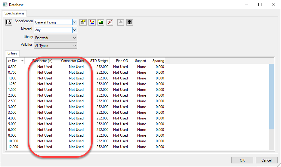
What we need to do here is set the Connectors in the Breakpoints to “Not Used”. Note, if the Connector you unlocked earlier didn’t change to something other that what it was, you most likely don’t have this issue but still could…it could just be configured to use the Connector the ITM was set to.

You might have to hunt around for which settings apply. It could be on the ‘Any’ material or a specific material the ITM is using. The ‘Valid For’ could have it in ‘All Types’ or ‘Straights Only’. It’s possible too that you don’t have any breakpoints in the Specification at all. If that’s the case, then your Specification is likely already good. But if it’s not, simply ensure the Connectors are all set to “Not Used”.

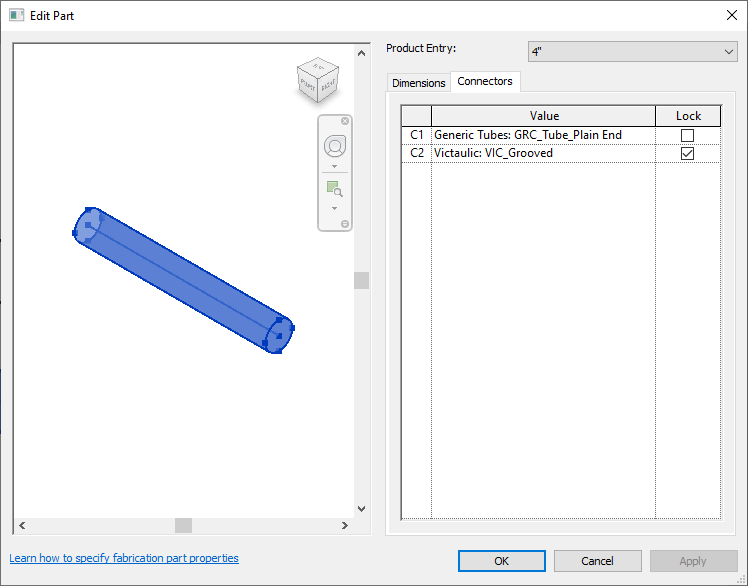
Once your Specification is setup correctly (if it was a problem in the first place) you can go back to your ITM for the pipe and unlock both connectors but leave them set to the Connector it typically uses.

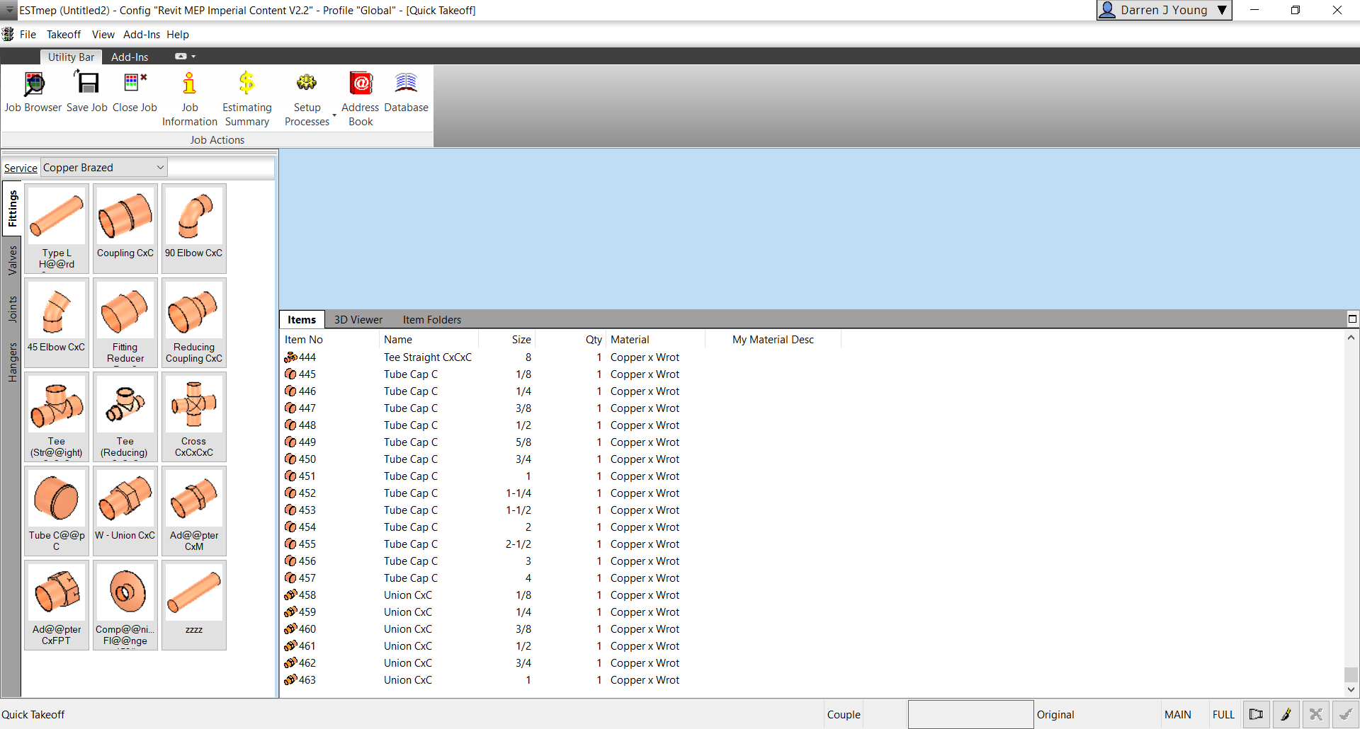
Once everything is set properly, Revit will then let your Grooved Coupling be placed in the run of pipe.

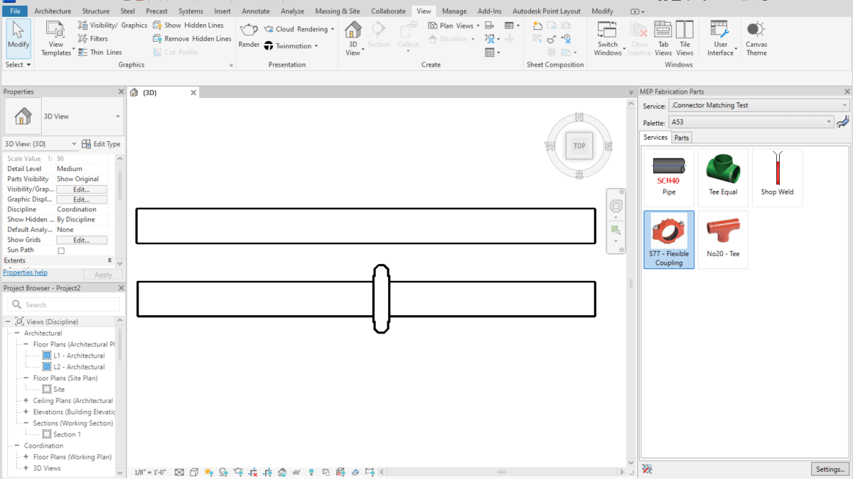
If you Double-Click on one of the pieces of pipe, you can see the Connectors are now set to a Groove for the end where the Coupling is.


A Final Word

Note that these settings were added in 2020. If you’ve had your Database configuration a long time, they’re likely not set. Even Autodesk’s ‘Out of the Box’ configurations that shipped with 2024 don’t have these set. So you’re pretty much on your own to make it work.

If you do ANY Administration of your Database Configuration in 2019 or earlier, these settings will be lost. As I’ve advised many times earlier, pick a version for Administration and stick to it. If you have Admin permissions and use 2019 or earlier, all those settings get lost and because they’re not displayed, you won’t really know.

You can use these settings for all kinds of things. They don’t have to be limited to Grooved Couplings. Changing the end of Steel pipe to Threaded when Cutting in a Threaded Coupling, Threaded Adaptor, Threated Tee, Threaded Valve, etc. All of these things should have their connectors looked at and Matching setup. Just about any of those types of fittings in all materials should have Matching set.

Hope this helps improve your Revit workflow.

Takeoff One of Every Size in Product List

I’m occasionally asked how one would add one of every size in a product list to their job. This very easy using ESTmep or CAMduct. CADmep however does not have this capability.

Here are the steps….


Step 1:
Start ESTmep / CAMduct with a blank job.


Step 2:
Go to Item Folders and navigate to the folder with the ITM(s) you wish to takeoff all sizes for. Select all the ITM’s and press CTRL+SHIFT+Right-Click and select Takeoff All Product Sizes.


Step 3:
Go back to the Items tab and review all the sizes of each item you selected.


Why Would You Do This?

There’s several reasons this may be helpful to you.

  • Any Size with dimensional errors is quickly found
  • A simple report shows you where you may have holes in your data (Price, Labor, Product Info, etc.)
  • Produce a quick MAJ that can be opened in CADmep (OpenJob) to measure each size to ensure dimensional accuracy.

If the option is grayed out/disabled, you’re one or more of the ITM’s in your selection is NOT Product Listed. For this to work, all items you’ve selected must be Product Listed.

Script Library Updated / Enhanced

COD Script Library was updated for JOB and LIBRARY Scripts. You can download them for free here. Here’s a summary of changes.


Script Consolidation

In the past, there were 69 to 75 COD Scripts to export all the various properties to separate TXT files. Properties that have multiple entries per ITM like Connectors or Seams are still exported to separate files because the data columns don’t line up between them and there are multiple lines per ITM.

All other properties where it’s a single property per ITM like Spool or Material have all been consolidated to a single script and single TXT file. The WriteAllMiscProperties(Job).cod and WriteAllMiscProperties(Library).cod scripts are where you can extract all other properties so no matter what combination of properties you want, there’s less data files to sort through or scripts to run.


Improved Script Properties Display

The properties scripts were displayed script settings before running the script. They still are but additional properties are displayed where appropriate along with some additional properties the scripts now support (both covered later). In addition to the additional items, you’ll note that clicking the No button no longer cancels the script. Instead, clicking No takes you to the Advanced Configuration (also covered later) where you can change some of those settings.


Advanced Configuration – Scan Folder (LIBRARY Scripts Only)

By default, the script looks to the root of your ITM Library folder of your database. This value can now be changed to point anywhere else. You may want to point to a folder of ITM’s outside your Configuration if that’s where you store your ITM’s. You can also scan further down the folder structure so you can perhaps skip exporting Duct ITMs but instead scan and export Piping ITMs.

Here’s what this looks like. Note that the path may use forward slashes ( / ). You can however paste a new path that uses backslashes ( \ ) and it should still work. There’s no option in COD Scripts to allow you to browse to a folder so make sure you type or copy/paste carefully.


Advanced Configuration – Export File (JOB and LIBRARY Scripts)

Similar to the Scan folder configuration, you can now also change the default export file name and location. Specifications for specifying paths are the same as above.

Also note that while you CAN specify “CSV” as the file extension, I recommend using “TXT“. When Excel sees a CSV file, it just opens it without giving you the ability to specify how data is interpreted. Using a “TXT” extension makes Excel prompt you for “How” the file should be read like which character is used as the delimiter or defining which columns are Text vs other data types.

Some numerical data or values can be interpreted incorrectly by Excel if you don’t explicitly tell Excel to treat them like Text. A good example of this is the size 1-1/2″ or 1-1/4″. Excel thinks these are dates and will display them as 1/1/2012 or 1/1/2014 respectively if you don’t explicitly tell Excel to treat them as Text. Using that “TXT” extension on the export file is a safe guard against this issue.

A lot more detail that you likely wanted but hopefully it’s helpful, here’s what that looks like….

Note you may see an extra slash character between the path and file name. This is can happen if your MAP.INI (Edit Configuration Utility) includes or doesn’t include an ending slash. I may add code to clean this up later but COD Scripts and Fabrication seem tolerant of this extra slash so no need to worry about it (or edit it out if you like).


Advanced Configuration – Folder/Path Wildcard (LIBRARY Scripts Only)

Instead of editing the folder you’re going to scan, alternatively you can specify a wildcard to use to limit which folders to export data from. As an example, you could specify *WELDBEND* and properties will only be extracted for ITM’s within folders containing the name “Weldbend”. Wildcard specification is not CaSe SeNsItIvE. By default, the wildcard is ( * ) to extract from all folders. Here’s what that looks like…


Advanced Configuration – File Wildcard (LIBRARY Scripts Only)

Just like the Folder/Path Wildcard specification, you can specify a wildcard for which ITM files to extract properties from. As an example, you could enter *PIPE* and you would export only from ITM files that contained the work “Pipe”. Again, the wildcard is not CaSe SeNsItIvE. You can use both Folder and File wildcards to very narrowly specify your data export scope. Default wildcard is an ( * ) to extract from all ITM files. Here’s what that looks like…


Advanced Configuration – Delimiter (JOB and LIBRARY Scripts)

Data exports by default use a Comma ( , ) to create a Comma Separated Value file. If your Fabrication Database uses commas in folder names or ITM file names this can cause data fields to shift in Excel when opening the export file. If this is the case for you, you can specify a different character to use to separate the data fields in the export file. The Pipe ( | ) character is always a good “rarely used” character for this purpose.

As a side note, it’s not a good practice to have commas in folder or file names. You can read more about that here. This option is really here in case you’re stuck with commas and haven’t fixed them yet.


Advanced Configuration – Max Custom Data Index (Only Scripts that export Custom Data)

Only used for scripts that export Custom Data, you can specify the maximum Custom Index value. Unfortunately, COD scripts have no ability to determine how many custom data entries you have or which index numbers are used without jumping through some hoops. To work around this, you need to specify the maximum Custom Data Index value. The script will then loop through all those numbers and find which ones contain values and remembers them. It then exports only those custom index values so that the script runs efficiency.

By default the script uses 5000 as the maximum index number. But as you can see from the below example, the maximum index number is 10000 so we need to specify that. We look at all 10000 possibilities (it goes fairly quick) and takes note that there’s only 8 indices used and then extracts only those 8 from the ITM’s. In the past, the script would loop through all 10000 for each ITM really slowing things down. Now, even if your largest number is 6 or 7 digits (not recommended) the script will still be fairly quick.

Here’s what that Delimiter Character configuration option looks like…


Summary

In the past, if you didn’t like the export files names, where they went, or wanted to change the scope of which files or folders you extract data from, you could have always changed the COD script code yourself. You now shouldn’t have to. Hopefully this makes running these scripts a little more flexible and user friendly.

Fabrication Job Contains No Parts – Possible Fix?

Have you ever tried importing an MAJ into Revit and received the following error….Fabrication Job Contains No Parts.

There’s a lot of reasons this can occur and it’s NEVER because there are no parts. So much for Autodesk’s QA/QC and Error checking.

You may see this most commonly because parts used in the model contain data that’s no longer in your database. You’ve likely noticed from time to time database entries with curly braces around parts of the name like the following…

This happens when an entry in the database is used by an ITM but the database entry itself later gets deleted. Information is cached within the ITM so when it’s accessed, it creates a Proxy entry in your database if it was missing. Within the {Curley Braces} is the name of the object that created the entry.

While CADmep, ESTmep and CAMduct handle this fairly gracefully, Revit on the other hand does not. When it attempts to load an MAJ, it sees these entries and notices they’re missing from your database and prohibits you from importing the MAJ file. Revit thinks the database doesn’t match the MAJ and stops you cold!

A Possible Fix

If this is cause for the import error, you can use the following COD script to potentially work around the issue….

Take the following script and run in in CADmep, ESTmep or CAMduct. You should be logged in with Administrative Permissions while doing this. This script isn’t fixing Revit or the MAJ. What it’s doing is loading ALL the ITM’s from your Database Library into memory.

The process of loading all these ITM’s into memory creates all these proxy entries in your database. This way, when Revit attempts to import the MAJ, the data associated with those ITM’s are most likely present in your Database configuration. In many cases then results in a successful import of the MAJ.

If the Revit file you are importing the MAJ into already points to a Fabrication Configuration, you should reloaded the configuration FIRST before attempting to import the MAJ.

If for some reason this process still doesn’t work, verify that Revit is reading from the same database location as the version of CADmep, ESTmep or CAMduct where you ran the COD script.

In the event it still doesn’t work, there may be other reasons for the failure but this is often the most common, especially with MAJ’s created recently.

If it does work, you’ll want to use the other scripts I provide on this site to help analyze your database. You likely deleted those database entries in the first place for a reason. You either didn’t realize they were needed, or you didn’t know where they were used to repoint those ITM’s to a proper substitute. Those scripts can help you find which ITM’s use which database entries.

Hope this helps.

Autodesk Fabrication: Best Practice #12

Compress Fabrication Data Files.

Autodesk Fabrication configurations can Compress their data files. It’s a good idea to have this enabled. Not only does this make the files smaller and take up less space, it makes them faster to load. This increases your performance as the data is expanded in memory as opposed to read more data from disk.

You can enable this option in your database settings. Doing this does not automatically compress existing data that’s not already compressed. The following image shows a suggested sequence of operations. This would both enable compression and compress the existing data.

  1. First Enable Compression by selecting the Compress File to Save Disk Space toggle. Future writes to data tables will be compressed when if they are configured to.
  2. Next, enable the toggles for Compress Database Files (.MAP) and Compress Item Files (.ITM) options. This will tell Fabrication to Compress the existing Database and Item files. Also, “unselect” the Compress Jobs (.ESJ .MAJ) option.
  3. Click the Compress Now button. This compresses the Database and ITM files but will not scan your ESTmep and CAMduct job files.
  4. Once compressed, select the Compress Jobs (.ESJ .MAJ) option. This will compress all Future ESJ and MAJ files but not existing ones. If you wanted, you could have left that option selected in Step 2. However it would significantly increase the time it takes to perform the compression process. Because most of your ESJ and MAJ files are likely past jobs, there’s really no value in processing them now….but you could.
  5. Press the OK Button to save these settings.

Check Settings for Each Product, Version and User of Each Computer

You should also know that these settings are NOT saved in your configuration. The file that stores these settings is located here…

C:\Users\<user>\AppData\Local\Autodesk\Fabrication <version>\<product>\UserOpt.MAP

<user> = User's Windows Login Name
<version> = Autodesk product version. (e.g. 2018, 2019, 2020, etc.)
<product> = Autodesk Fabrication product (e.g. CADmep, ESTmep, CAMduct)

You can tell by the folders, that this setting is stored separately for each user on a computer. Because each product and each version is part of the path, those variations need to be set too.

Because Best Practice #9 tells you to use only one version for database administration, version may seem unimportant. But it IS important to know when you upgrade to a newer version for administration. Those versions should also have these settings reviewed.

Every user who does work in your database, should check each product and version for those settings. If they don’t, your work may compress files while their work may decompressed them.

Because clicking this just once makes it do it’s magic in your database, you don’t need to click the Compress Now button for each version, user, product or computer. The options merely need to be Set., telling those products what they should/should compressed or decompressed.

Autodesk Fabrication: Best Practice #11

Don’t use Commas (,) in Database Entry Names, ITM File Names, Don’t Use Them Anywhere.

Similar to Best Practice #1 (Don’t use Double Quotes), you should avoid using commas. Commas are the delimiting character in a CSV file. Using a comma can throw off the data columns in data exports that use the CSV file format.

Below, you can see Autodesk let a comma slip into a file name in their Metric Configuration.Yes – Ancillary in Ancillary Kit

Merging Autodesk Fabrication Databases (Method 4 of 4)

Warning: This is last part (4 of a 4) in a series on merging Autodesk Fabrication Databases. Autodesk Fabrication software is extremely powerful and flexible but that also makes it very fragile. Use the below guidance with caution. I highly recommend backing up your configuration before attempting anything I’ve recommended. It never hurts to have a firm grasp of how Autodesk Fabrication functions from an administrative perspective. Consider yourself warned!

Method 4: MERGEDB (CAMduct only)

This last method is very quick and powerful but only available in CAMduct. If you’re not a CAMduct user, simply download and install to perform this process while in the 30-day trail period.

This method doesn’t let you pick and choose individual database entries but you can pick certain database types and quickly merge all of them into a new configuration. Unlike prior methods were you typically started in the old Database to export an *.IOX / *.IEZ file or create a Proxy ITM first, in this process, you start with the database you want the items to be imported into.

In addition to make of the database entries Method 1 supported, this method also supports these additional entries.

CutoutsLeadsRates
FacingsMaterialsSilencers
Hanger SpecificationsNotchesVanes

To use this method, start CAMduct and type CTRL-SHIFT-C to display the command window as shown below.

From the command window, type MERGEDB and press <Enter>. This doesn’t do anything other than tell you the data the command needs as shown below. The Strict/Unstrict options tell the merge process if it should only look at the name or the data to determine if it’s duplicate. If you choose strict and the items are already in your database, something as simple as 3 vs 4 digits after a decimal will cause a duplicate entry. In most cases, unstrict is all that’s required.

For this example, we’ll type MERGEDB UNSTRICT NOTCHES to import all the notches from one database to another as shown below.

When you press enter, you’re prompted to select a folder. You should select the Database folder of the old database you want to merge into your current database.

If new items are found, you’ll be notified and prompted if you want to save the changes or not.

Upon completion of the merge, you’ll need to go to those items in your database and make permanent any you intend to keep and remove those you didn’t want.

Pros:
> Only way to import some database entry type.
> Easiest way to merge the bulk of 2 database together.
> Extremely fast and efficient.
Cons:
> Requires CAMduct.
> Can not pick and choose database entries, only database types.
> Requires post merge cleanup of deletion or making entries permanent

Merging Autodesk Fabrication Databases (Method 3 of 4)

Warning: This is Part 3 of a 4 part series on merging Autodesk Fabrication Databases. Autodesk Fabrication software is extremely powerful and flexible but that also makes it very fragile. Use the below guidance with caution. I highly recommend backing up your configuration before attempting anything I’ve recommended. It never hurts to have a firm grasp of how Autodesk Fabrication functions from an administrative perspective. Consider yourself warned!

Method 3: Service Export/Import

This method is very similar to Method 2 above except that it works on a full service and all the items within it’s service template. If you have an existing service you want to post from one Database to another, this is a great method. Even if you just have a library of multiple ITM’s, it’s very common to create a transport service. That service holds those ITM’s and can be used as a means to get ITM’s from one database to another. Here are the steps.

From CADmep, type EXPORTSYS at the command line or in ESTmep or CAMduct, while in the Takeoff screen, select Takeoff -> Services -> Export as shown below…

This displays the Export Systems dialog. Use the Browse button to select the location and name of the *.IEZ export file. Select the service(s) you wish to export and click the Export button.

Importing is a similar process. Type IMPORTSYS from CADmep or from the Takeoff screen in ESTmep or CAMduct, select Takeoff -> Services -> Import as shown below…

You are prompted to select an *.IEZ file for import. The file will be read and display all the services that were exported. Select those you want to import and click Import.

Because IEZ imports can contain a lot of data, it’s likely you may have a lot of duplicates. Upon import, you are prompted if you’d like to Import ALL or NEWER item. Select as appropriate for your situation as shown below.

If Estimating data is found, you are also prompted to Replace or Keep existing tables. Because the database you are importing to is likely your current desired database, I’d recommend to Keep existing tables and only Replace if you intend to bring over labor and cost data in the Import. Once again, choose the option that best suits your needs as shown below.

Like in Method 1 earlier, if the import finds a service or template it thinks is the same, it’ll prompt you how to proceed. I highly recommend NOT selecting the “….To All” options as it’s common for the database index to cause false matches and mislead you.

You are prompted once the import is complete. As with Method 2, if ITM’s imported through this process contain new database entries, you’ll need to find those and make them permanent in a similar way.

Pros:
> Easiest way to import large numbers if ITM’s and their related database entries.
> Easy way to import Services and Service Templates
Cons:
> Slowest of all process do to all the verification the Import process needs to do.
> Can Import a lot more data than you intend.
> Can not pick and choose individual database entries to import

Stay tuned for Method 4 in my next and last post in this series.

Merging Autodesk Fabrication Databases (Method 2 of 4)

Warning: This is Part 2 of a 4 part series on merging Autodesk Fabrication Databases. Autodesk Fabrication software is extremely powerful and flexible but that also makes it very fragile. Use the below guidance with caution. I highly recommend backing up your configuration before attempting anything I’ve recommended. It never hurts to have a firm grasp of how Autodesk Fabrication functions from an administrative perspective. Consider yourself warned!

Method 2: ITM’s as Proxy

Another method of transferring data from one database to another is by using ITM’s. Simpy take an existing ITM or make a new one and set some of it’s properties to those you want to transfer. After you’ve completed this, copy the ITM to your desired database.

In your desired database, right-click on the newly copied ITM from the Folders view and select Edit or Properties as shown below.

Once the Edit Item or Item Properties dialogs are displayed, you can simply close them. The only purpose in calling them up was to force Fabrication to read all of their settings which in turn causes them to be created as Proxy entries in your database if they don’t already exist.

Once the database entries are in your new database, you’ll want to navigate to those database entries and make the proxy items permanent as shown below.

Pros:
> Every property an ITM uses is supported.
> Dependent database entries supported (e.g. Fixings on a Support)
Cons:
> Can bring in more properties than you want which need to be cleaned.
> Time consuming for large property sets as multiple ITM’s required.
> Proxy items must be manually made permanent afterward

Stay tuned for Method 3 of 4 in my next post.

Microsoft PowerBI w/Autodesk Fabrication

For years, I’ve shared my Fabrication COD scripts with the industry. These can be used to examine database content using Excel.

Tyler Phillips of Bruner Corporation recently posted a nice article on LinkedIn about using Microsoft PowerBI. His PowerBI dashboard provides a great way to help visualize the data behind your Autodesk Fabrication content.

Simply put, the scripts I share dump property data to multiple CSV files. Tyler used that data for some of the PowerBI data sources. This allowed him to built a dashboard which helps him visualize and navigate the data in a more meaningful way. And better yet, he publish a fantastic article on LinkedIn that explains how to do it.

Microsoft PowerBI Dashboard of Autodesk Fabrication Content

This is a great example of leveraging data from multiple sources. PowerBI help you mash it together to give you meaningful information that’s simple to understand and navigate.

If you’ve ever struggled with ESTmep reporting, just think of the possibilities. By taking the above concept and using it across CSV exports from ESTmep you could easily overcome gaps in estimating reporting.

Great job Tyler! Really appreciate you sharing.


Additional Resources