Over the years, I’ve written a number of scripts helpful for managing an Autodesk Fabrication configuration. I’ve given them away in my Autodesk University session I’ve taught so they’ve circulated around a bit.
I’ve rewritten most, streamlined them, made enhancements, added others, etc, etc. Because I’m always updating and changing them, I thought I’d host them here too. I can then just post when I update them.
There’s are 2 sets of scripts covering the following topics…
Debugging Properties Scripts
Job Item Scripts
Library Item Scripts
One set is for use in 2019.0 and earlier versions (but work in any version), the others are designed for 2019.1 and later when Autodesk added support for the Pattern Number property.
You can get to the scripts from the menu or click here. The scripts are free to use for all except employees of ENGworks or anyone working on the behalf of ENGworks. (contractors, consultants, etc.) who are prohibited from use.
When you build content, it’s often desirable to have certain dimensions or options locked. This even applies to connectors, seams and dampers but to a lesser degree.
If you have a lot of Dimensions and/or Options to Lock or Unlock, you don’t have to individually pick each one. You can lock or unlock many very quickly provided they’re in a row.
The trick is simple….pick the button to lock/unlock the first field you want to change, and then while still holding the pick button drag your mouse up or down. This is a fast an efficient way to lock large groups of properties without picking each one.
The following recording shows this process. We’re using Pattern Number (CID) 910 as our example.
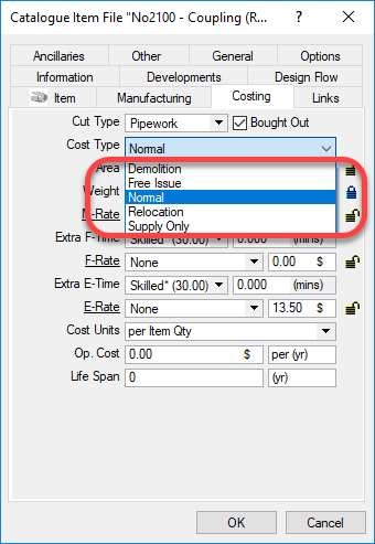
When you build Autodesk Fabrication content, you may have noticed one of the properties “Cost Type“. You can see this setting is shown in the following image.
If you do some searching online, you may run across an explanation for some but not all. As Autodesk explains in it’s online help….
Normal – Reads the Material, Fabrication, and Installation tables to generate costs of all materials, fabrication labor and installation labor.
Supply Only – Reads the Material and Fabrication tables to generate the same costs of material and fabrication but NOT installation. (You’d typically use this if you are fabricating for others outside your company.)
Free Issue – Reads only the Install table when calculating costs.
This leaves two remaining values that can be set. These are not documented by Autodesk. These two serve the same purpose…
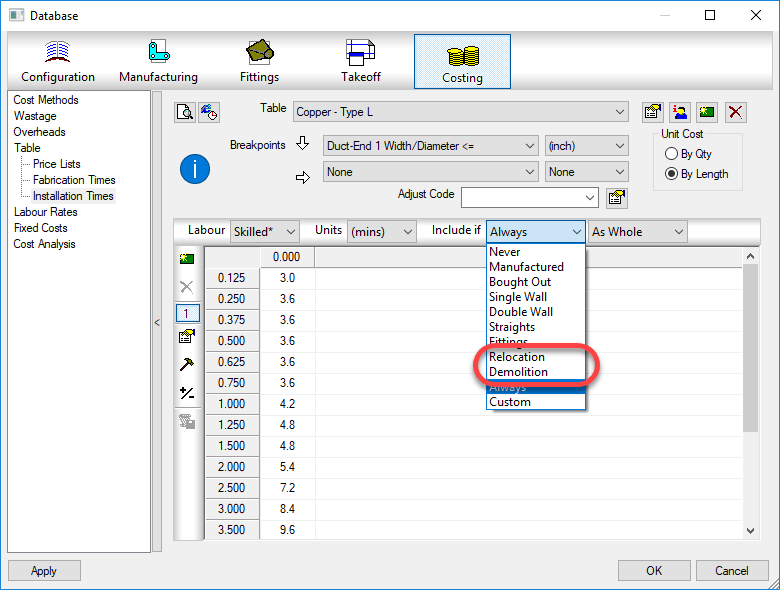
Demolition – Used as a filter for Labor table value sets
Relocation – Used as a filter for Labor table value sets
Using these values would allow you to build a labor table for relocation that would include uninstall and reinstall time. You could also use the demolition value to build a labor table for removal only of an item.
While you would think these only would apply to an install table, these filter values are also available for the fabrication table. At the very least, this opens up the possibility of using it in creative ways to serve whatever purpose you like.
I’ve been asked from time to time, which Autodesk Fabrication Patterns (CID’s) support exporting points for field layout. If you want to use Trimble, Topcon or similar hardware for field layout like hanger inserts for MEP, these points are important.
So, with this post, we’ll show you that information but also hope to accomplish something else in the process. I’ll walk you through a couple ways to do it, one significantly better than the other. It’s not really important that you know how to do this same process again, once you have the information, you’ll likely save it somewhere. However, knowing how to do this process will hopefully give you ideas about techniques you can use for other types of data mining and extraction. It’s not hard after all, you just need to get creative with few things you already likely know how to do.
If you’d rather just get to the data, scroll to the end of this post and you’ll find the list of pattern numbers. Otherwise, follow along and at the same time, explore some options for learning how to get this type of data yourself.
Step 1 – Get a copy of Every CID
The MAKEPAT command in Fabrication is how we create new ITM’s based on a particular CID. Most people working with Fabrication for a while know that. What they may not know is that you don’t have to randomly type patter numbers and run the command hundreds of times. CAMduct can do them all at once. If you don’ have CAMduct, install a trail version which you can download from Autodesk’s web site.
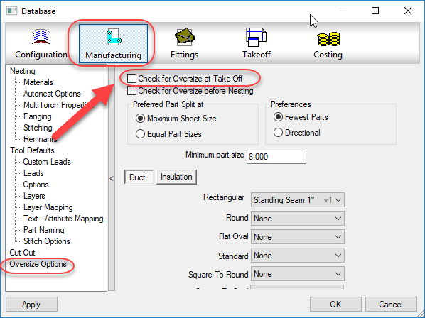
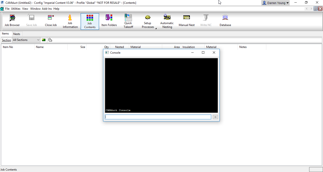
After starting CAMduct with a new project, the first step is to turn off prompting for Oversize which would keep prompting you on some large sheet metal patterns that exceed the material size. We turn this off to make the process run without pausing for user input.
Turn OFF Oversize Checking
The next step is to display CAMduct’s Command Window screen by pressing “CTRL-SHIFT-C“.
Pressing “CTRL-SHIFT-C” on the Keyboard Displays the Command Window.
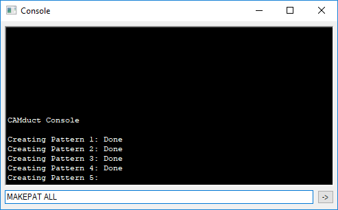
Next, in the Command Window, type the command “MAKEPAT ALL” and press <Enter>. (Note that the Command Window is also part of ESTmep but the MAKEPAT ALL function is not supported in ESTmep, only CAMduct.)
“MAKEPAT ALL” will Create One of Each Pattern
Depending on the speed and resources of your computer or even other running processes, this can appear as if it’s locked up CAMduct at times. However, be patient and let it sit. Unless the software crashes, the process will complete. I’ve seen cases where it can take over 10 minutes or more.
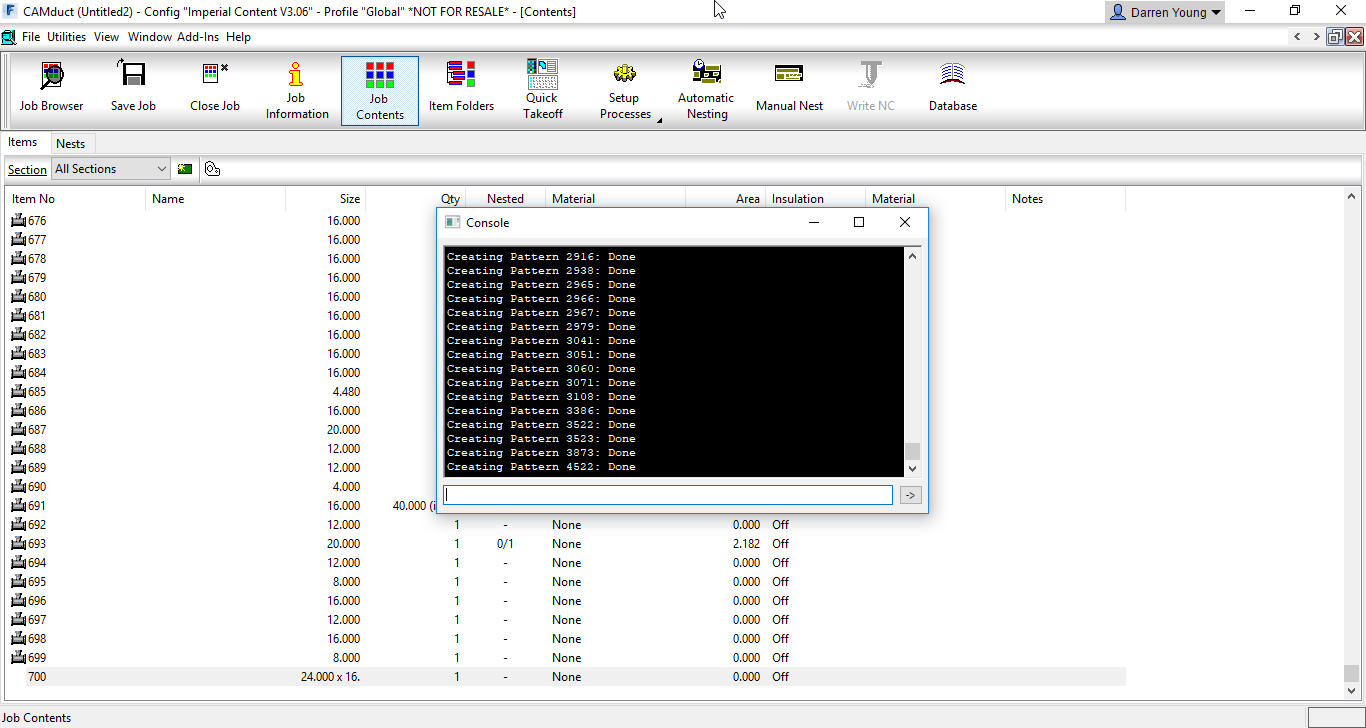
When complete, there is no prompt. You’ll just notice the cursor back in the Command Window’s typing area. The last pattern should be CID 4522. You’ll also see the Job Contents will contain each pattern that was successfully taken off. These patterns exist only in this job, not in your database so you’ll want to save this job in CAMduct’s MAJ file format for future reference. If you like, you can download my copy here.
All Successful and Supported CID’s Are Now in One MAJ.
Step 2 – Examine Patterns
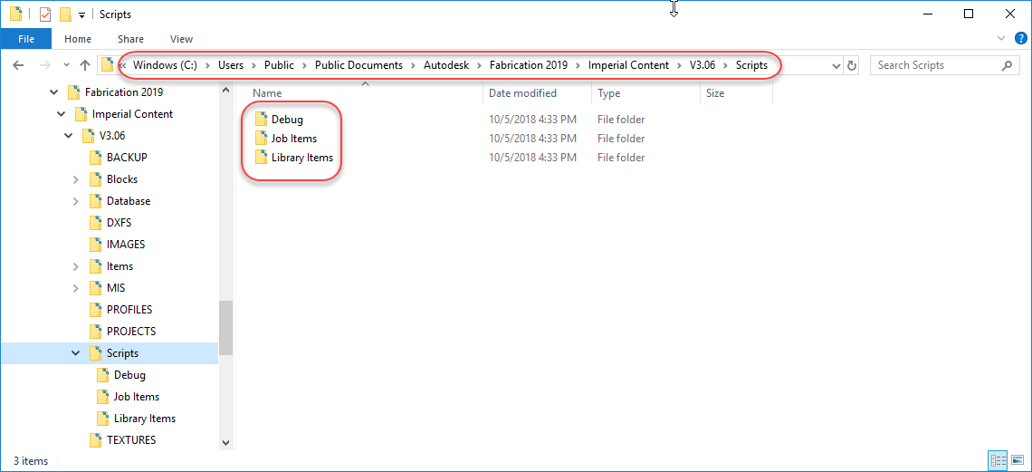
Now that we have a file with all the patterns, we can examine them. There’s a lot, and doing each one individually will take a lot of time. If you’ve ever been to one of my Autodesk University sessions, you’ll know that I frequently supply a lot of Fabrication COD scripts. This is where they can come in handy. You can download them here.
I typically place my COD scripts under the Scripts folder in my Fabrication Configuration like so…
Scripts Extracted to the Configuration’s “Scripts” Folder
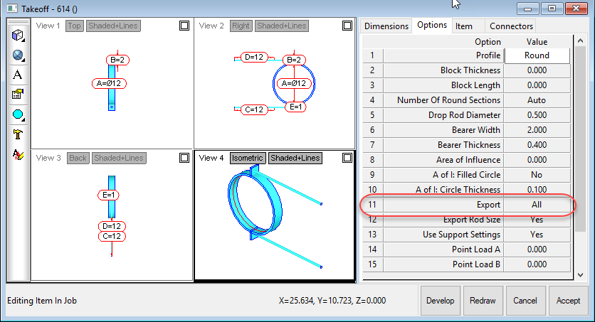
If you look at a Hanger CID (1249 for example) you’ll see in it’s Options tab that there’s an “Export” option that tells CADmep if it should export field layout points or not.
The “Export” Option Controls Field Layout Point Exports
We’ll use this to determine which CID’s export points which is where the scripts come in. For this example, we’ll be using the following script…
.\Scripts\Job Items\WriteAllOptions (Job).cod
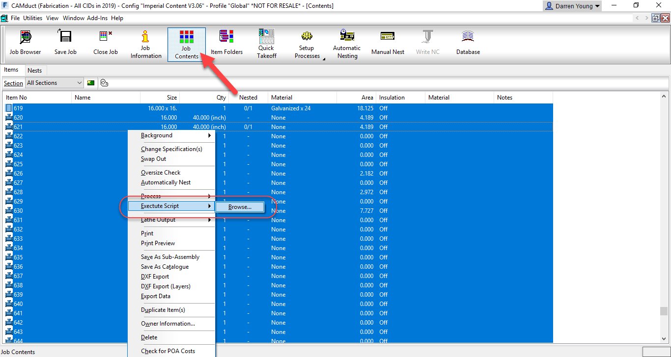
This script will write all the Options for all the item in the CAMduct Job. To do this, click the Job Contents button on the ribbon, select all the items in the job, Right-Click and select the Execute Script option then browse to the above referenced COD script.
Use “Execute Script” to Run a COD Script on All Selected Items
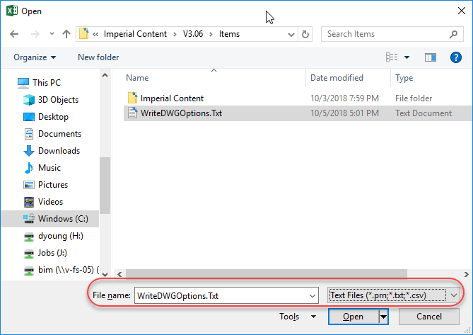
After the script completes, it’ll have written to a text file all the options and their values for each of the items in the job along with their CID. You can find the file located in the root of your fabrication configuration’s Items folder. This is the file you’ll be looking for…
.\Items\WriteDWGOptions.Txt
Using Microsoft Excel, open the text file. Make sure you change the file extension to Text Files so Excel displays the file you created.
Change Excel’s File Type to “Text Files (*.prn;*txt;*.csv)“
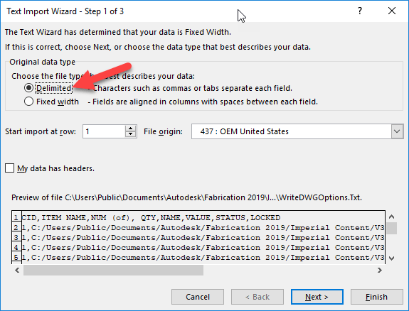
This will bring up Excel’s Text Import Wizard. Select the “Delimited” radio button and click Next.
Use “Delimited” as the Import Option in Excel
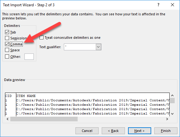
In the next screen of the Wizard, you’ll select the “Comma” toggle as one of the delimiters and then click the Next button.
Use the “Comma” Option as the Delimiter
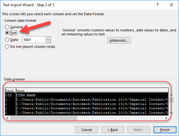
In the next wizard page, you’ll highlight all the columns in the bottom portion and select the “Text” radio button to tell Excel to treat all the columns as text. From there, click the Finish button.
Change All Columns to “Text” Data Format
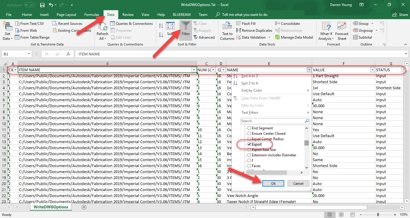
From here, Excel displays a line item for each option of each item in the job. You can now quickly filter this list by clicking the Data ribbon menu and selecting the Filter button. This adds a drop down arrow control in the first row of each column. “Column E” is the “Name” of the option. When you click the drop down arrow in that column, you see a list of all the values. Uncheck the top “(Select All)” option to deselect all the values and then scroll to the “Export” option and select it. This tells Excel to only display rows containing this text. From here, click the OK button.
Use AutoFilter to Display Only the Rows that Contain the “Export” Option
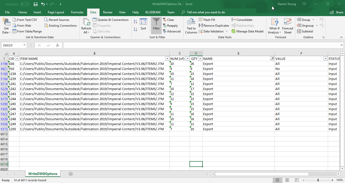
Once this is done, you’ll get a very short list in Excel. The left most column, “Column A“, is the CID or Pattern Number for each item in the job (we make one of each pattern) that has the Export option.
Excel Quickly Filters Options to Only Those With an “Export” Option.
So now we have a list of Pattern Numbers that you know will export points for field layout. You also learned how you can use some of the scripts I have to Export and mine data from your fabrication configuration. The question you have to ask now is, are we certain this data is correct?
Autodesk Fabrication allows you to rename Dimension and Option names. That would suggest that it’s possible to miss an option that was renamed to something other than Export. In this case, because we used CAMduct to create all the patterns from scratch, it’s most likely that it’ll have all the default names for it’s Options and Dimensions.
We’re still not in the clear however. It’s possible some patterns that support field layout points don’t have an Export option or have a similar option but name it something else. For this reason, we can’t be certain we know ALL the CID’s but we can be certain that we know SOME of them.
Step 3 – An Second (Better) Approach
How can we be certain we know ALL the CID’s that support field layout point exports? The simple answer is to export all of the items and see which have points.
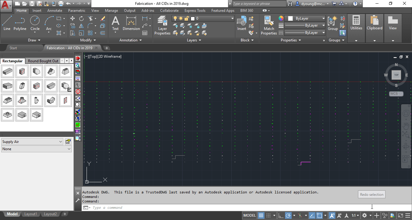
To do this, we can use Fabrication CADmep. Start AutoCAD and load Fabrication CADmep. From here, if you saved the job you created in CAMduct as an MAJ file, you can use the “OpenJob” command in CADmep to import all those Items into CADmep.
CADmep will display all the items in the Fab Viewer before importing. Simply click the OK button to complete the import process.
MAJ Imported into CADmep Displays Items in an Array
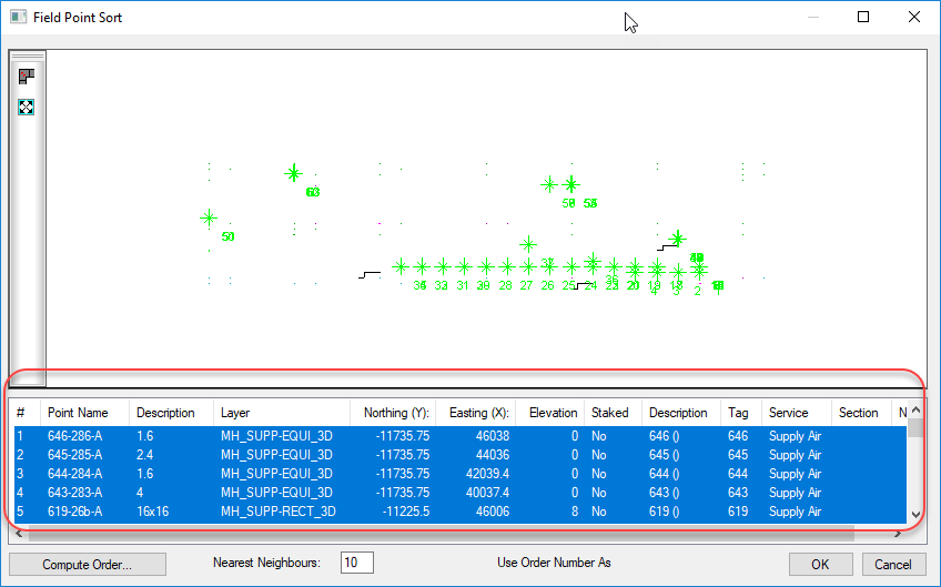
Once the MAJ is imported, CADmep will display all the Items in a large array. From here, we can use the “FPOINTE” command (previously the “TRIME” command) to export all the points. When the command asks you to select the points, type “ALL” at the select objects prompt. This will display the Field Point Sort dialog.
All Items Supporting Field Point Exports Will Appear in this Dialog.
Now we could finish exporting the points at this time but we’re not going to. This is because not all the information in this window actually gets exported. Specifically, the Tag column which displays the Item number (not the CID) and we need to know which Item number (which CAMduct sequentially numbered) to find the Item so we can check it’s CID later.
Instead, we’re going to select all the points in the bottom of the dialog, Right-Click and select “Copy” to copy the entries into the Windows Clipboard.
Without going into all the steps here, the next thing we naturally want to try is to Paste the items into Excel. If you go ahead and try it, you’ll likely notice that the coordinate fields are missing (that’s an interesting story with some history in itself) which isn’t a big deal for our purpose. But upon closer examination, you’ll also see that the columns aren’t lining up in Excel. Pasting this data into Excel is not going to work without a lot of fixing of data.
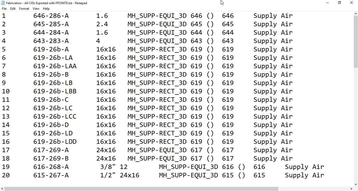
So the next thing I try, I paste the data into a blank Notepad file to see what it looks like there.
“FPOINTE” Data Pasted Into Notepad
Looking at the data in Notepad, you can easily see there’s columns. A little lower in the file you see the columns tend to shift, bit there’s definitely columns there. A little further experimentation using the cursor and keyboard arrow keys you can see the cursor jump between columns. This is a clear indication that columns are separated with Tab character. If your data doesn’t look like this, try looking at the Word Wrap setting in the Format pull down menu and turning it off.
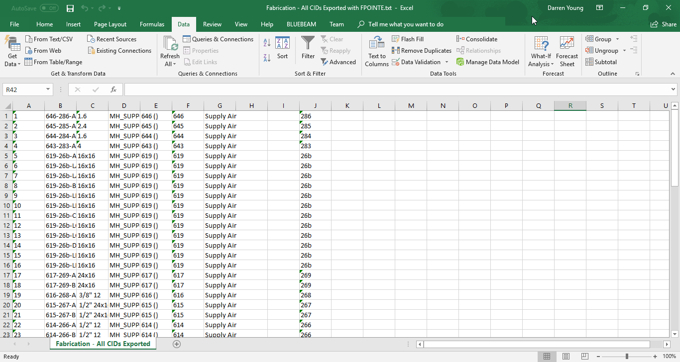
At this point, you should be guessing what’s next. Save the TXT file and open it in Excel like you did earlier. The only difference is that instead of selecting a comma as a delimiter, you want to make sure that Tab is selected as the delimiter, The resulting data in Excel should look like the following image…
“FPOINTE” Data Opened in Excel
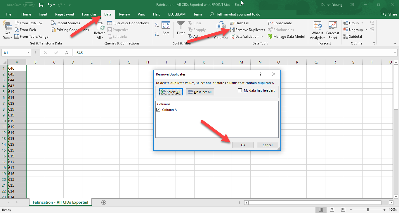
Lets keep in mind that some patterns export more than one point so there’s duplicates that aren’t needed. Additionally, we really don’t care about any of the exported data except for the Item Number which was in the Tag column in the Field Point Sort. This column is in Column F of Excel. For this reason, we’ll delete all the columns except for F. When you’re done, Column F will shift to Column A. From here, we can use Excel’s Remove Duplicates function on the Data ribbon to remove the duplicate Item Numbers.
Remove All Columns Except the One With the Tag Data and Run Remove Duplicates
When you’re done, you’ll have a nice short list of each pattern’s ItemNumber that was able to be exported. Note, this is the sequential Item Number that CAMduct assigned when creating the patterns. This is NOTthe CID or Pattern Number. Keep this Excel file opened for now, we’ll get back to it later.
At this point, it wouldn’t be too hard to look up each item number in CADmep or CAMduct and check it’s properties to find the Pattern Number of the item. But that can still take some time. We’ll go through another step to automatically look up the Item Number and show you the Pattern Number of the Item.
Step 4 – Using The Item Number to Find The Pattern Number (CID)
We need to somehow tie the Item Number to the CID or PatternNumber. To accomplish this, we’ll again turn to our scripts. All of my COD Scripts typically export the CID number. There’s also typically a script for each property. So we’ll be using the following script which will export the CID and Item Number of all the items in our drawing.
.\Scripts\Job Items\WriteAllNumbers (Job).cod
Type “ExecuteScript” in CADmep and browse to the above script file. At the Select Objects prompt, type “ALL” to select all the items in the drawing to run the script on. When the script is finished, it’ll export the data to the root of the Items folder like before. Open it just the same as you did prior making sure you use a Comma for a delimiter and change the column data types to Text.
.\Items\WriteDWGNumbers.Txt
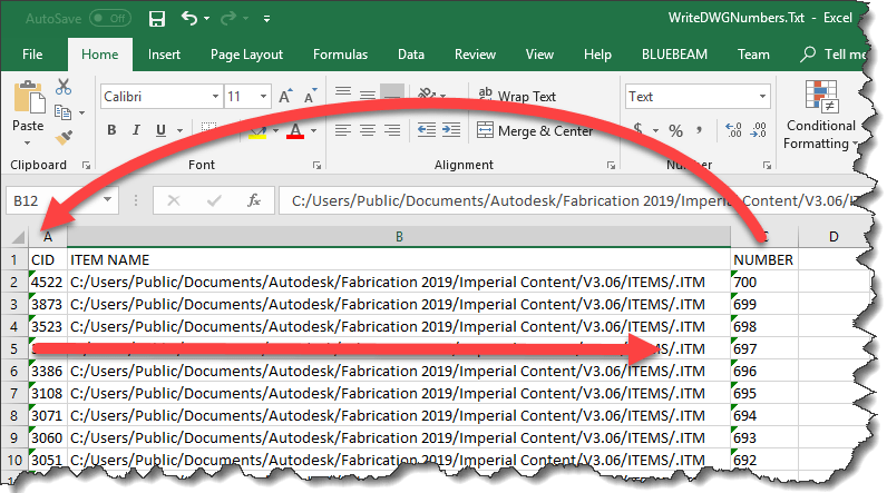
Once you open the Item Number export file, it’ll look like the following image. This is what we’ll use to cross reference the Item Numbers with their corresponding Pattern Number.
Item Numbers Exported from our Job
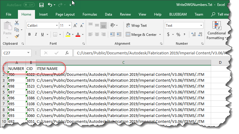
Because we need to look up the Item Number in Excel, we’ll want to move the Number column in front of the CID column. This is because the function that we’re going to use in Excel needs the number it’s looking up in the first column. When complete, your data should look like the following image…
Number Column Moved To The First Column
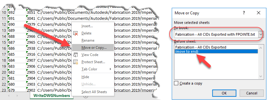
Next, we’ll move this entire worksheet to the first Excel file that contains our points. Right-Click on the worksheet tab and select “Move or Copy…“, use the drop down list in the Move or Copy dialog to select the spreadsheet with your exported point data and move it to the end. Click OK when done. This will move the sheet with exported Item Numbers and CID’s to the end of the other workbook.
Move the Exported Item Numbers Worksheet to Your Point Export File
When you’re done, you’ll have two separate tabs in your first Workbook. One lists only the Item Numbers of the successfully exported points, the other contains the Item Numbers and corresponding CID’s.
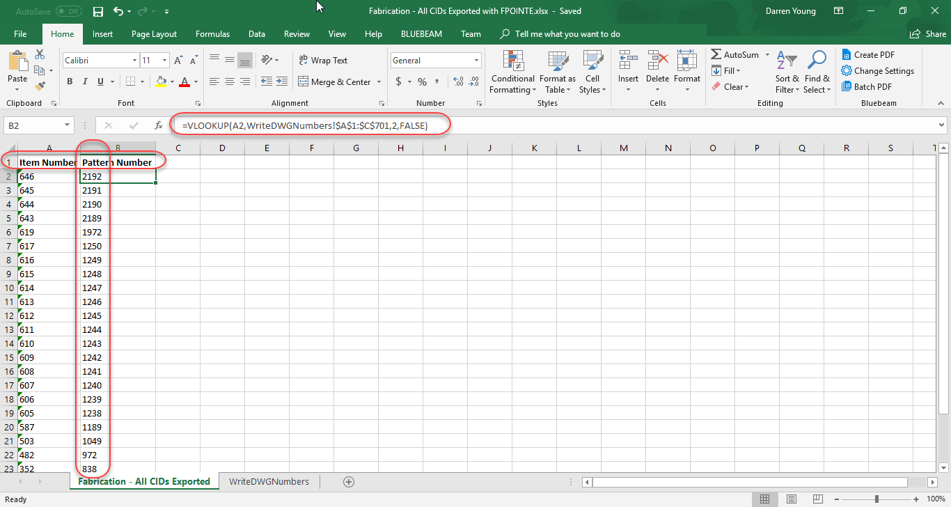
Go to the first worksheet tab where it lists a single column with the Items Numbers that were exported. Add a blank row at the top and type the text “Item Number” in Column A and “Pattern Number” in Column B. In cell B2, type the following formula…
=VLOOKUP(A2,WriteDWGNumbers!$A$1:$C$701,2,FALSE)
After typing the formula, copy it to the remaining cells in the column to complete the cross reference.
This formula tells Excel to look at the ItemNumber, and find it in the first column of the range in the second worksheet that lists all the ItemNumbers and CID’s. When it finds that corresponding ItemNumber, return the value from the second column which contains the CID. The “$” in the cell address of the range tells Excel to NOT increment the range address as the formula is copied down…you want to look at the same range no matter what. Finally, the False flag tells Excel to do a strict match and not try to interpret close results. Your finished data should look like the following…
This completes our final list of Pattern Numbers (CID’s) that support Field Point Exports. You can look at my Excel file by downloading it from here.
Note that when we looked only at Items that contained the Export option, there were 14 patterns. However when we tested against the actual point export in CADmep, we ended up with 25 patterns. Our final list of PatternNumbers (CID’s) that support field point exports is here…
149
321
322
838
972
1049
1189
1238
1239
1240
1241
1242
1243
1244
1245
1246
1247
1248
1249
1250
1972
2189
2190
2191
2192
Hopefully you’ve gained an idea on how to use some of the scripts, Excel and other processes to mine and extract data from your Fabrication configuration. It’s using techniques like these that allow me to assemble a lot of the information I have on this site like which versions of software have which CIDs’s and which ones are supported in Revit.
Just a quick note, I’ve updated the Revit Fabrication Parts CID Support page. Pattern Number #1175 was inadvertently set to “No” but has now been changed to “Yes”. This pattern allows 3d Models from CAD to be converted to ITM’s that work in Revit.
Make sure ALL of your ITM content has a Database ID assigned to it.
A database ID is a unique identifier for content. There should be a single Database ID for any ITM that is NOT Product Listed. For Product Listed ITM’s, there should be Database ID for each entry in the product list.
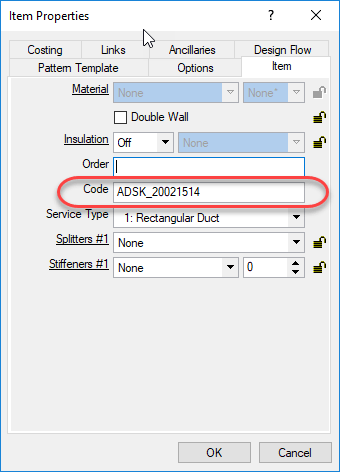
For ITM’s that are not product listed (typically fabricated sheet metal fittings or other content where the ITM only represents one size, you can put the Database ID in the “Code” field of the ITM Properties as shown in the following image…
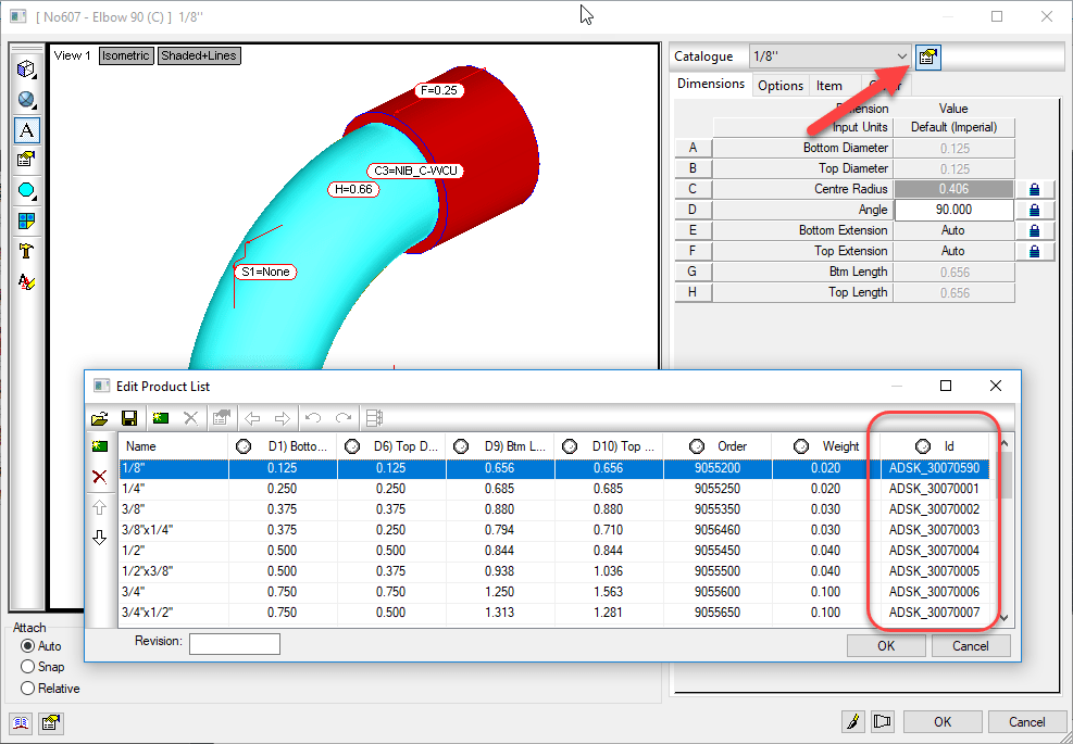
For ITM’s that are Product Listed, the Database ID should be in the ID column of the Product List. When you place an instance of a product listed ITM in your model, you select a size from the product list, When you select that size, the Database ID associated with that size it automatically entered into the Code field of the ITM Properties like shown earlier, The following image shows the Database ID column in a Product List…
Why Use A Database ID?
The Database ID is a useful component to managing an Autodesk Fabrication configuration. This Database ID can be referenced by other aspects of Autodesk Fabrication should you choose to use them. The Database ID is what can link your content to….
Price lists
Fabrication Labor
Installation Labor
Product Information (ProdInfo)
Even if you don’t use ESTmep for estimating and don’t want to use the Price and/or Labor features of the database, Product Information is tied to the Database ID and is used to store additional meta data about your content like Manufacturer, Size, Description, etc. Even if you’re not using ProdInfo now, it’s still a good idea to use Database ID’s because adding them to the content is the most time consuming part. It’s easy to add them when building content, more cumbersome later after the fact. If all your content had Database ID’s assigned, it’s much easier to implement ProdInfo, Price and/or Labor later down the road.
The following Video shows how to access the Database ID of Product Listed and Non-Product Listed ITM’s. It also shows you 2 different sizes of a product listed ITM in a drawing and how Autodesk Fabrication automatically assigned the Database ID from the Product List for the corresponding size into the Code field of the ITM Properties.
Key Database ID Takeaways
Here’s a few pointers when working with Database ID’s:
Each Database ID should be unique and not assigned to other content or sizes.
Managing Database ID’s using a spreadsheet or other database makes managing them much easier.
Your database ID can be anything you want but should have some sort of naming standard associated with it.
Your Database ID Naming standard can be as simple as a prefix followed by incremental numbers to something complex with special codes and formatting to indicate other aspects of your content. (e.g. Valves, Pipe, Sheetmetal, etc)
You can use Autodesk or other Vendors ID’s if they already have them assigned and use your for anything you create or replace them all with your own company Database ID’s if you are particular about naming standards,
Don’t reuse ID’s if the content that once used them is now obsolete. Legacy/Archive drawings still reference these numbers. Simply flag them as being obsolete in the Spreadsheet you are managing them with.
In CAMduct using OPUS parts and/or ITM’s with developments that have had edits made to them can on occasion cause some headaches. The following process can be used to resolve 2 different issues in CAMduct, Those are….
Retain edited pattern developments
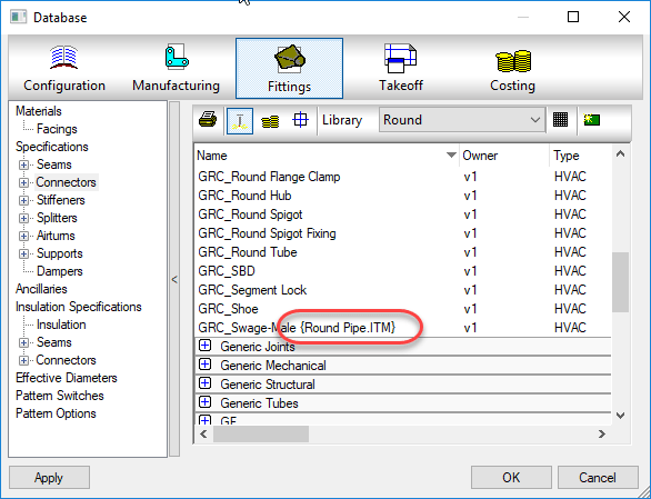
Eliminate proxy database entries with {curly brackets}
1) Retaining Edited Developments
It’s fairly common for CAMduct users to edit pattern developments. Occasionally, they may want to save these edited developments for later use. A good example is using a number of separate ITM’s for damper blades. Each ITM is a different size with perhaps some edits to the pattern for slots/holes for U-Bolts, notching to clear screws, etc. A CAMduct user can use any CID Pattern for the basis of their edits. For example, they could use an Elbow CID, delete all the developments belonging to the elbow and redraw something completely from scratch. The problem with this is that if you ever try to change materials or edit the ITM in any other way, the development edits are lost and the original development is back minus your changes.
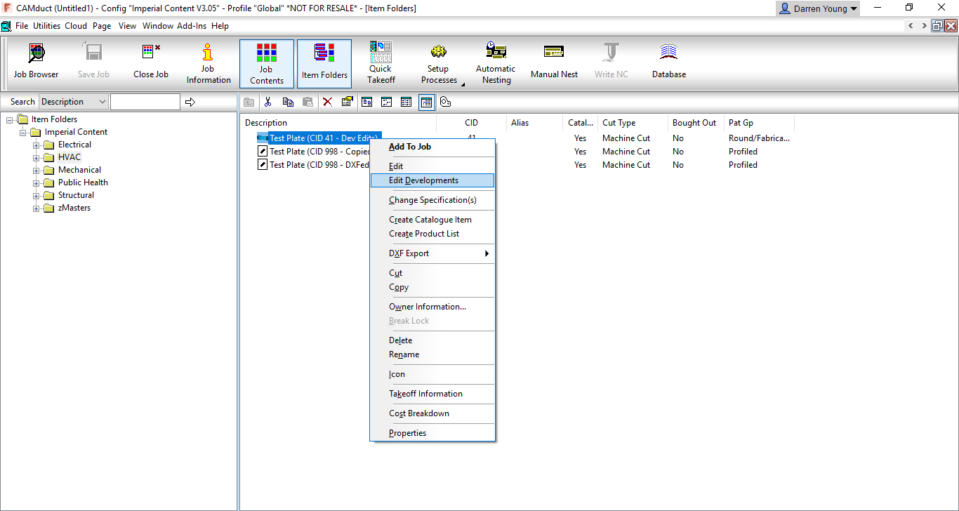
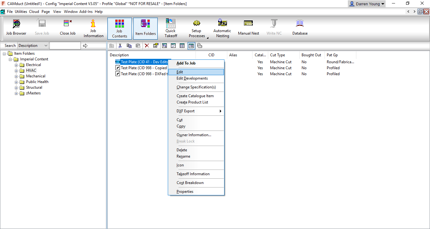
In the following image, you can see that Right-Clicking on an ITM made from CID 41 offers a couple editing options In this case, we’re going to select the Edit Developments option.
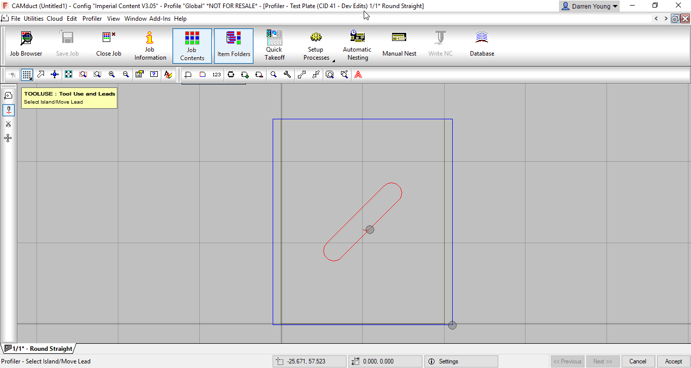
When you select the Edit Developments option, you’re brought to the OPUS Part editor shown in the next image. Here you’ll see that there’s been a 45 degree slot added to the development.
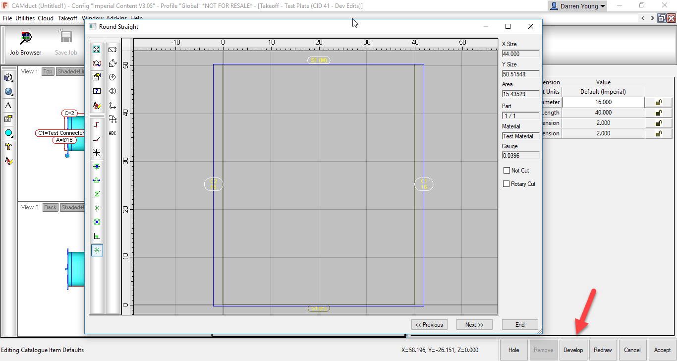
On the other hand, you can also Right-Click on the ITM and select EDITfrom the menu as shown in the next image.
This option brings up the standard ITM editor which you should be fairly familiar with. The part you see in the ITM editor may not look anything like the development, it may look very similar or in fact be the same part developed if there were no edits made. From the ITM Editor, click the “Develop” button in the lower right and you’ll again be brought to a dialog that displays the part(s) developments. This time you’ll notice that the 45 degree slot is not shown. In fact, it’s displaying the unedited development for the CID you’ve selected based on the Dimensions, Options, etc. as entered in the ITM Editor. From the ITM editor, the dimensions, options and other settings drive the size/shape of the developments. It wouldn’t know what to do with your edits so it gets rid of them,
When you Edit the part in the ITM Editor, even if to change something simple as a material, the pattern gets redeveloped and the edits you made to the developments are lost. This makes ITM’s utilized this way very prone to getting wiped out of you’re not careful.
The solution to protecting these developments is to change them to a different CID pattern used exclusively for OPUS parts…CID 998 (or 0 depending how it’s created) OPUS parts contain only the development and not the originating ITM pattern. When you select the Edit option for an OPUS part, you go directly to the Opus Editor.
2) Proxy Database Entries
The other problem with edited developments is they can bring in proxy entries into your database. As an example, lets say the CID Pattern used was pointed to a Material, Connector or Seam in your database that no longer exists, was renamed or moved to a new group. As explained earlier, you can’t go back and edit the ITM to change them or your edits to the development will get wiped out. You can change the seams/connectors/materials with a COD script to avoid this but most people are not familiar with this process. When you use this type of ITM, the old materials, seams and.or connectors that were originally used come back into your database with {brackets} around them.
Even then, a Development Part is assigned a material separate from the material on the ITM. There is no way to change the development part’s material from a COD script. You can however, change it from the Development tab of the Properties dialog.
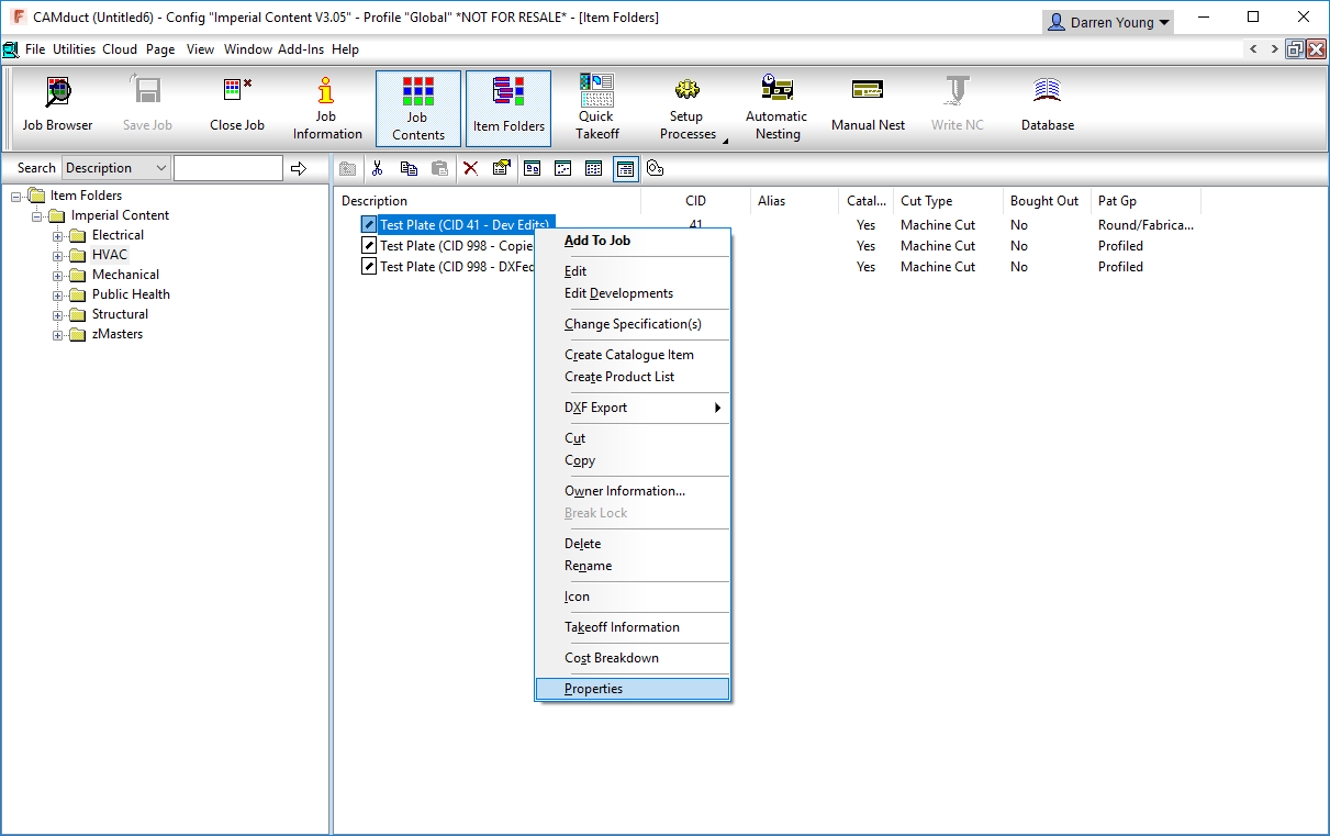
The following image shows the Propertiesoption when Right-Clicking on an ITM.
After clicking the Properties option, the properties dialog box will appear. Here, you can switch to the Developmentstab to see the developments of the ITM. From this tab, you can then edit the Development Part material. This still presents a few possible difficulties…
You have to edit the development part material one ITM at a time.
You can’t script changing the development part material
You can’t set the development part material to “None” as this is not an option
Depending on the “Catalog” and/or other options of the ITM, the Development Part material drop down may not be enabled for selection.
As we mentioned earlier, a native OPUS part CID only contains the developments and avoids a lot of these issues.
The obvious thing to do is to go to the edited developments of the original ITM and copy the geometry to the Windows Clipboard (Ctrl-C). You could then go to an Empty OPUS part and paste the object there from the Windows Clipboard (Ctrl-V). But again, this presents yet more issues.
Even though you would only be copying/pasting the development entities, CAMduct still remembers there were seams and connectors applied and this data hitch hikes along for the ride on the geometry even though you can’t see it. Except now, you can’t get to the ITM editor any longer to change them and COD scripts can’t find any connectors to seams to change because an Opus part doesn’t have those options. The information i there,, hidden, but inaccessible.
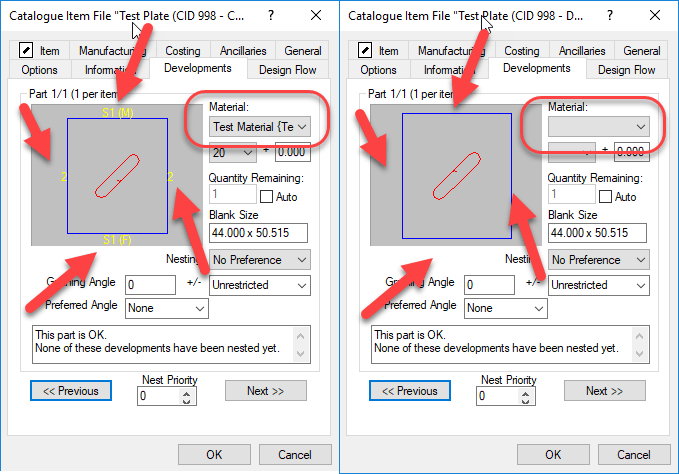
In the following image, you’ll see two ITM Properties dialog boxes side by side.
In the LEFT image, you’ll see what the Developmentstab looks like on an ITM with edited Developments or even. It alo look this way on an OPUS part that was created using Copy/Paste method from a different CID. The OPUS Editor doesn’t show you, but the Developments tab in Properties displays text for the Seams/Connectors. The image in the RIGHT is an OPUS part created with a completely different process that we’ll show shortly.
Also notice the image on the LEFT shows a material in the drop down list where as the image on the RIGHT does not. Using the ITM that was the source of the Left image will bring in proxy Materials, Seams and Connectors if they no longer exist in your configuration. Using the ITM that was the source for the Right image, will not bring in these Proxy items. This means if you later reorganize your materials/seams/connectors, the ITM for the left image will keep corrupting your database and the ITM for the right image will not.
The Solution
To resolve both of these issues, Edited Developments on none OPUS CID Patterns and eliminating proxy database entries, we can use the same process. This process involve creating DXF files for the existing ITM’s an then creating new ITM’s from those same DXF files.
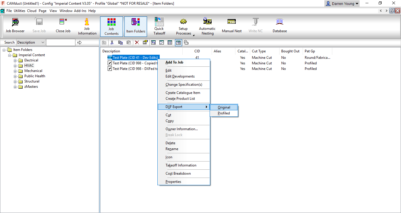
The following image shows how to Right-Click on the ITM and Export the DXF to a file on disk.
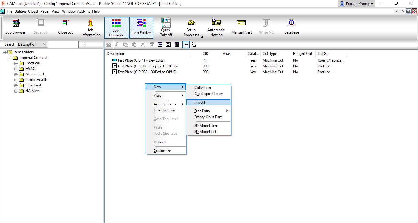
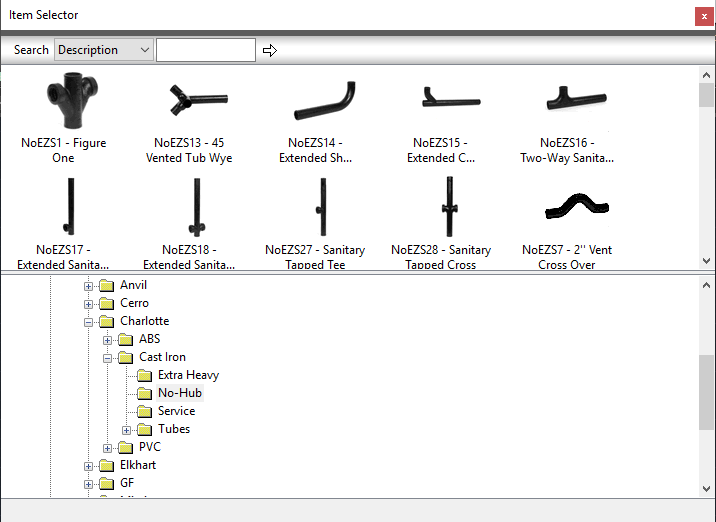
Once the DXF files are create, you can Right-Click on an empty area of the Folder display and select New, then Import as shown in the following image.
The import process is fairly self explanatory end leaves you in the Opus part editor. Here are can make any final changes and when clicking OK, you can overwrite the existing ITM or give it a new name. This new ITM is based on CID 998, has no material set in the developments and contains no traces of any seams or connectors. You also don’t need to worry about accidentally deleting the edited developments because editing this ITM brings you directly to the OPUS Part editor and does not bring you to the ITM editor.
Additional Considerations
What’s nice about the above process, is that you can select multiple ITM’s at one time to Export to DXF. And when you Import the DXF’s, you can also select multiple DXF files. There will be some additional or changed prompts in this process but it allows you to quickly clean up your existing OPUS parts and protect ITM’s made from non-OPUS CID’s.
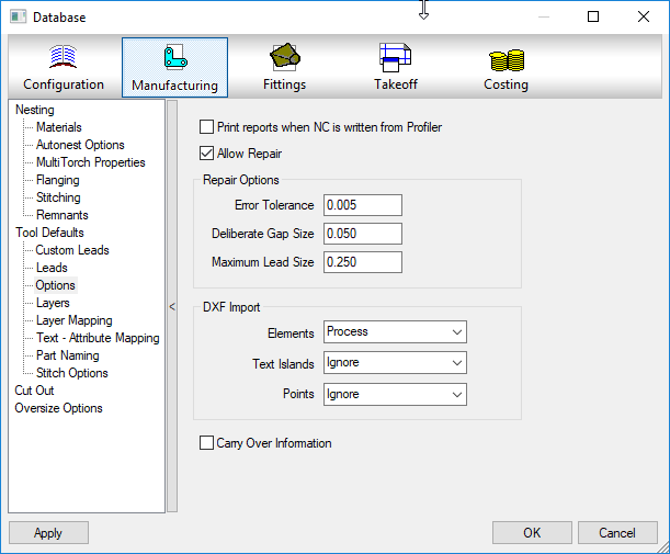
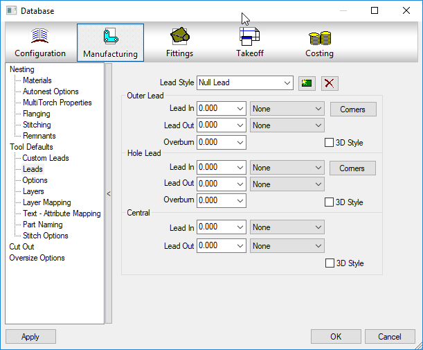
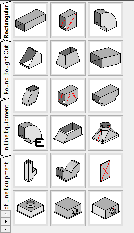
One thing to watch for is complex geometry with a lot of curves/arcs/lines. You’d typically see this type of geometry when cutting patterns that represent art or a lot of text. When dealing with this type of geometry, before you Import the DXF’s, you may want to explore some of the settings used by CAMduct to automatically detect a complete profile without any small gaps or overlaps causing issues, The following image shows where these settings can be made.
Use of these settings goes beyond the scope of this article so I’d recommend using a little trial and error to get the best results only if you encounter problems with importing DXF’s.
The other thing to watch for is the Kerf or offset used on the tools assigned to the profiled part and which types of lead in/out paths are used to start and end the profiles, While you can always edit these settings of the OPUS parts later on a case by case basis, you can set the defaults to use in CAMduct. The following image shows where to set these default values.
Taking a Closer Look
If you want to take a closer look, at the entire process, you can view the process this these two videos.
Here’s the process to cleanup a single ITM…
Here’s the process to cleanup a multiple ITMs…
If you want to play with a couple ITM’s yourself, you can download them here.
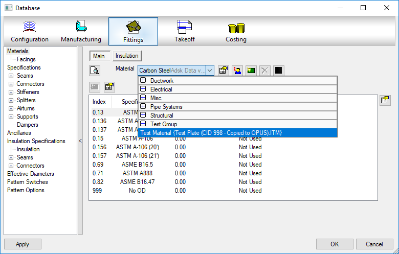
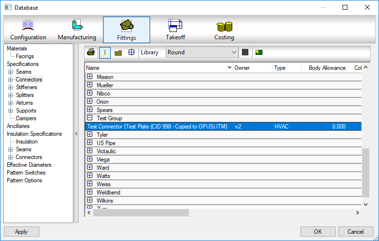
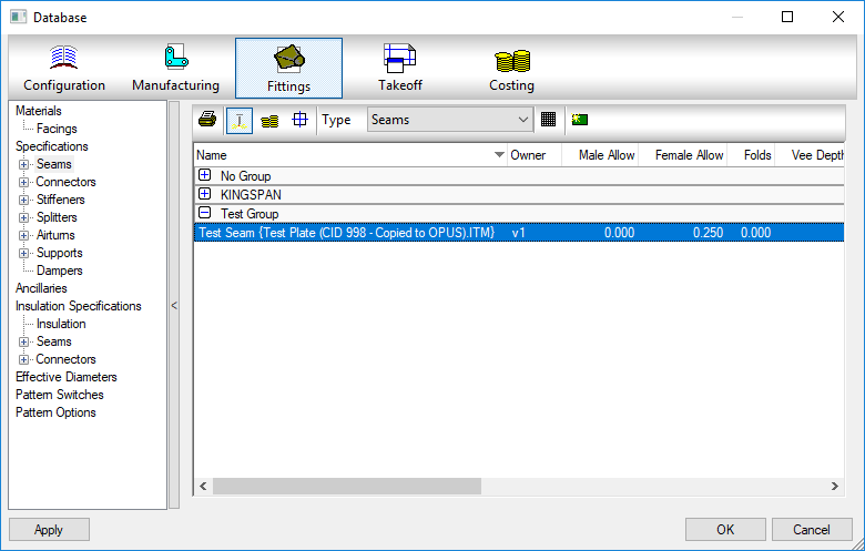
If you play with the original ITM Test Plate (CID 41 – Dev Edits).ITM or the OPUS part created with the flawed Copy//Paste method Test Plate (CID 998 – Copied to OPUS).ITM, you’ll see a custom Material, Seam and Connector added to your database, Delete them out and try again with the next ITM. You’ll see that the ITM created with the DXF process Test Plate (CID 998 – DXFed to OPUS).ITM we showed earlier does not bring the old materials, seams or connectors shown in the below images.
Don’t leave proxy items in your fabrication database.
You’ll notice these as they appear with curly brackets { } around a piece of text like an ITM name or DWG name.
These proxy objects can show up many places. Services, Service Templates, Materials, Connectors, Seams, etc. They occur when an ITM or drawing containing ITM’s references a database entry that no longer exists in your Fabrication configuration. As an example, if you delete a connector from your database, let’s say “Copper Cup” then later add an ITM to your drawing that contains a reference to that connector, it gets added back to your configuration and displays the ITM name in the curly brackets.
If there’s bracketed items in your database they should either be made permanent or deleted. If deleted, they may keep coming back. If you truly want them gone, you need to find the objects bringing them back and update them to the new item in your database configuration that they should point to.
A properly managed Fabrication database configuration should have everything configured properly. Items with curly brackets are an indication that things are not configured properly.
Future posts will explain various techniques to help identify where these bracketed items come from as well as how to correct them efficiently.
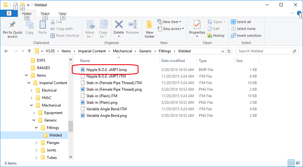
If you’ve been using an Autodesk Fabrication configuration for a long time, like back before Autodesk acquired MAP Software Ltd, you may have a lot of content that’s using Bitmap (*.BMP) files. These image files are used on a couple key locations….
1: Service Palettes….
2: Folders Dialog….
If you’re Fabrication configuration uses BMP files for images, you should consider converting them to PNG files. There’s a number of utilities that will do this in bulk for you if you have a lot. My favorite is using TechSmith’s SnagIt Editor but there are others.
Use Windows Explorer and browse to your content. You can use the search functionality in the upper right corner and search on *.BMP to see how many Bitmap images there are. Or you can browse folder by folder looking for them. Hint: Sorting by type can speed with this too.
Once you convert the BMP’s place the PNG files in the same folder using the same name as the BMP and then delete the BMP files. Doing this will reduce the size of the files which in turn speeds the display of your service palettes and folder’s list.