For MEP fabricators using Revit, Autodesk has finally released the Fabrication Extension for Revit 2020. This extension allows you to Export and Import MAJ files from Revit. Imports have always been problematic and prone to issues but Exports typically work well.
You can download the extension 3 different ways…
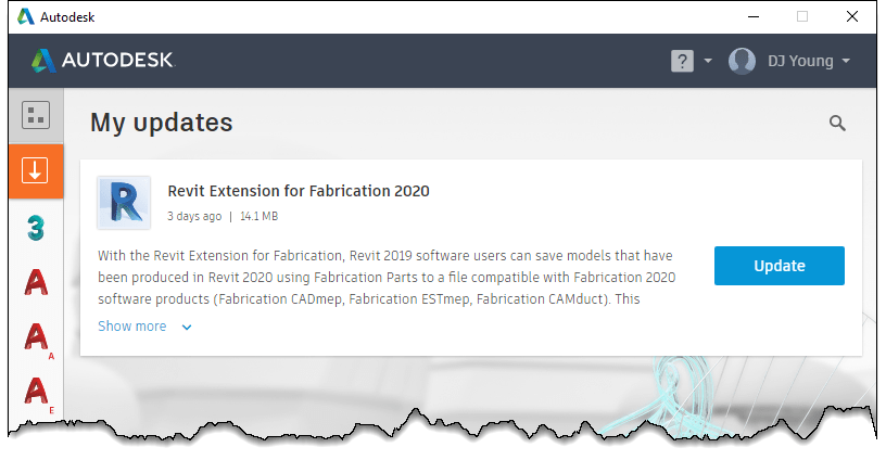
1: Autodesk Desktop App
Likely the easiest way, check your Autodesk Desktop App for available updates and download/install from there.
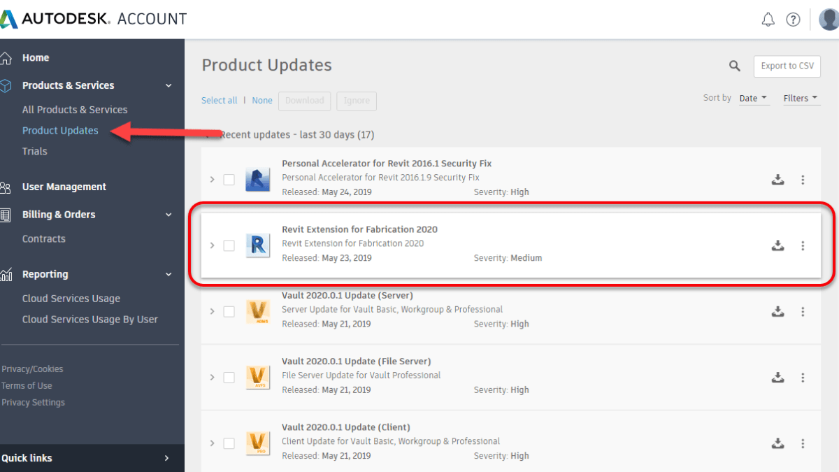
2: Autodesk Accounts – Updates
The second easiest way is to log into your Autodesk Accounts portal and click the Product Updates button on the left. This lists all the available product updates associated with the products you have.
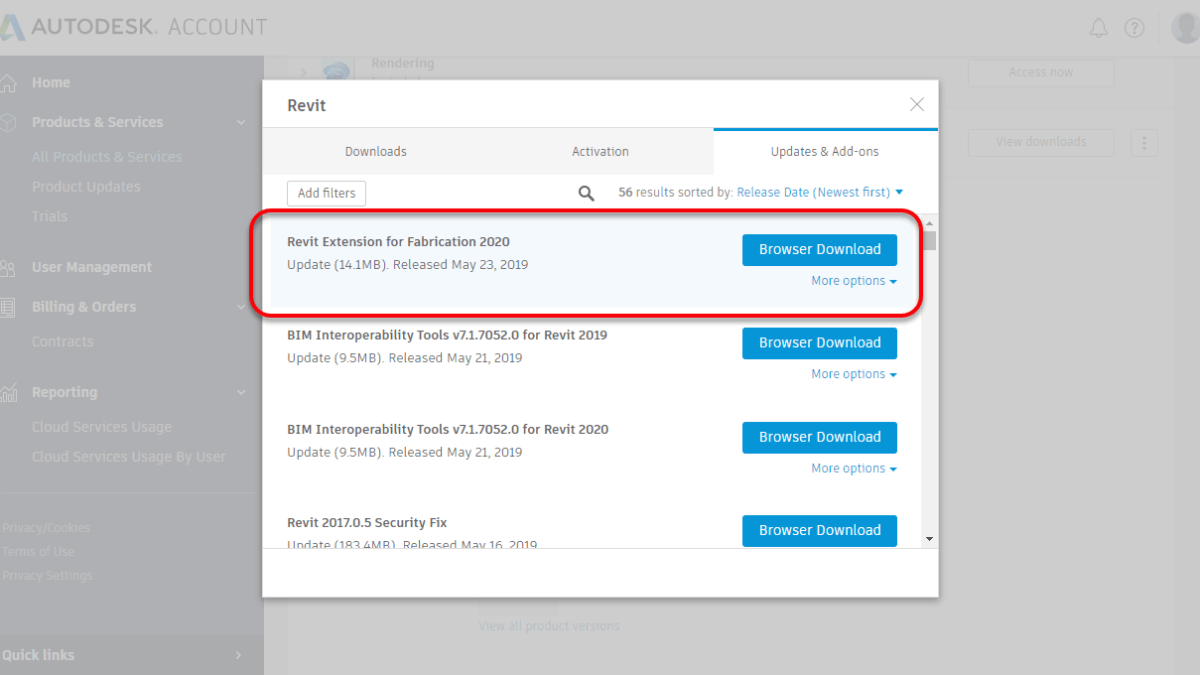
3: Product Download Page – Updates
The least easy way to get product updates is to do to the Revit product downloads and look at the Updates section. Takes a little longer to get here but all the updates associated with a single product can be found here.
If you’re using 2017 or older Autodesk products, your software may stop working on June 15th, 2019. Newer versions will continue to work but may have intermittent issues with any of their cloud related services. Exact services and product versions vary.
Many products and services use Transport Layer Security (TLS) 1.0/1.1. Due to known vulnerabilities, on June 15, 2019, Autodesk will be updating their systems to no longer support this protocol. This service is what’s used for Autodesk to determine your “Identity” when providing access to your products and services.
You can read more about the affected products and versions here. This article is specific to which older products will stop working completely. It does not cover newer products that have services which may stop working.
Newer products (2018-2020) Not mentioned in the Autodesk articles are also affected subject to the following….
Ancillary related services and newer products have their own security updates
Access to core product is Not an issue
Ancillary cloud connected services May be affected such as…
Revit Cloud Worksharing
Personal Accelerator (PAC) for Revit Cloud Worksharing
Communicator
Energy Analysis
Dynamo Package Search/Upload
P&ID Modeler
Licensing type of product does NOT matter
Most products have updates available however there are a few that do not. Autodesk Fabrication products in version 2014 or 2015 do not have updates. So unless you’re using those version with a Single User Subscription, you don’t need to worry. If you are using a product that does not have an update, you will need to upgrade to continue working.
Resource information for Autodesk Fabrication has been updated. They now include information on the 2020 version of CADmep, ESTmep and CAMduct. In short, nothing has changed.
The FabViewer Command Reference did have one new command added. However, this was not new to the 2020 version. The CADmep 2019.1 update added a command which was missed previously.
If you use network licenses or create network deployments of CADmep, CAMduct or ESTmep you may encounter errors. Autodesk incorrectly pathed the Network License Manager files in the SETUP.INI files.
Even if you are using Stand Alone or User Based Subscription licenses but build Network Deployments, if you configure the deployment to include all components in the deployment (recommended if you plan on modifying the deployment later) you can encounter errors.
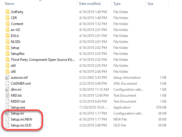
To correct the errors, you can replace the SETUP.INI files that are part of the installation with the ones provided in the following ZIP file…
Before you overwrite your installation’s SETUP.INI file, it’s a good idea to backup the original. The root of my installation folder looks like this…
At some point, I would expect Autodesk will update their download data and provide the proper files. Because of this, I would highly recommend NOT replacing the SETUP.INI files unless you encounter issues.
What’s Different?
If you’re curious what’s different between the two, you can open the INI files in Notepad or other text editor and view them there.
The original file contains this at the end of one of the entries…
Third-Party Component Open Source EULAs:x64\en-US\Tools\NLM.msi
The new SETUP.INI files have updated it to this…
Third-Party Component Open Source EULAs:x86\AdskLicensing\NLM\x64\NLM.msi
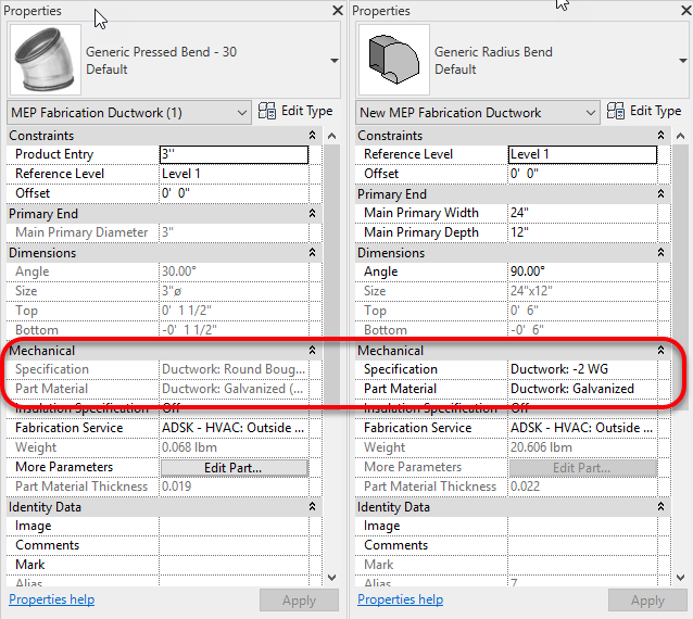
Fabrication Parts in Revit don’t always allow editing of their Material or Specification properties. Look at the below side by side images. Revit’s properties can be seen grayed out on the left but those on the right are not.
Material & Specification Properties – Left Read Only, Right = Read/Write
Revit can obscure the reason for this because you have no access to edit your Fabrication Database within the Revit environment. The answer however is quite simple.
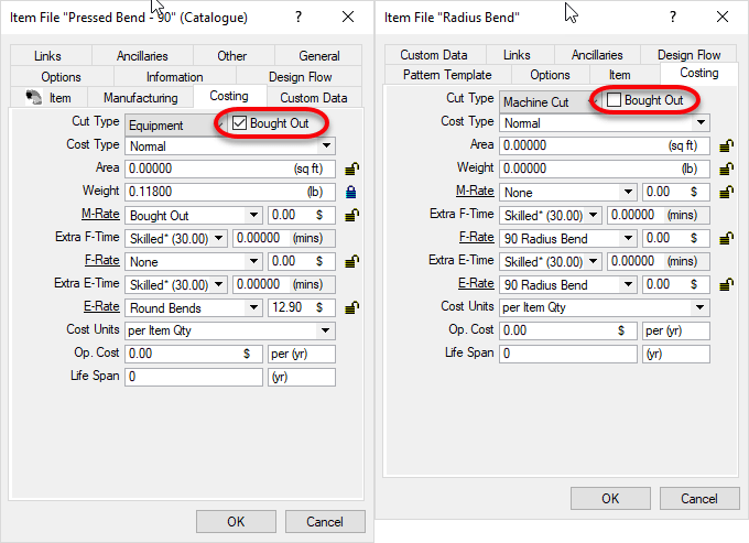
Fabrication Parts with the “BoughtOut” property set do not allow editing of Material or Specification. After all, a bought item is typically static and can’t be easily changed. Non-BoughtOut items do allow editing of the Material and Specification properties.
The following is another side by side image of Fabrication Part properties. The properties on the left have the BoughtOut property set. The properties on the right do not have the BoughtOut flag set. While not accessible from Revit, any of the other Autodesk Fabrication products can display and edit the BoughtOut property.
The following is an overview of the changes made to the AutoCAD 2020 release.
New Dark Theme
Improvements to the clarity and crispness of the dark theme. Similar sharpening was also applied to the light theme as well.
Background colors were optimized the with the icon colors to provide the optimum contrast without distracting from the workspace, where the focus should be.
Ribbon Access
Application button > Options > Display tab > Window Elements > Color Scheme
New Commands
None.
New System Variables
None.
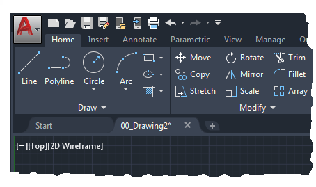
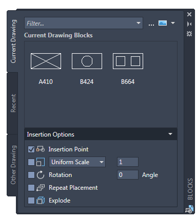
Blocks Palette
Redesigning the Insert dialog box was to provide better visual previews of blocks in the workflow for inserting blocks. The palette increases efficiency for finding and inserting multiple blocks-including the new Repeat Placement option, which can save you a step in some cases.
Key features in the new blocks palette facilitate your specifying and inserting blocks efficiently from a most recently used list or from specified drawings. Three tabs are available to provide the following:
The Current Drawing tab displays all the block definitions in the current drawing either as icons or as a list.
The Recent Blocks tab displays all the most recently inserted blocks either as icons or a list regardless of the current drawing. These persist between drawings and sessions. You can remove a block from this tab by right clicking it and choosing Remove from Recent List.
The Other Drawing tab provides a way of navigating to folders from which you can choose drawings either to insert as blocks or to choose from the blocks defined in those drawings. These drawings and blocks also persist between drawings and sessions.
The top of the palette includes several controls, including a field for applying wildcard filters to the block names, and several options for different thumbnail sizes and list styles.
Ribbon Access
Home tab > Block panel > Insert.
Access from the ribbon provides a gallery of the blocks available in the current drawing together with two new options, Recent Blocks and Blocks from other Drawings.
These two options open the Blocks palette either to the Recent tab or the Other Drawing tab. The gallery displays the same content as the Current Drawing tab.
Placing blocks from the palette can be accomplished by dragging and dropping or clicking and placing.
New and Changed Commands
BLOCKSPALETTE – Opens the Blocks palette.
BLOCKSPALETTECLOSE – Closes the Blocks Palette.
CLASSICINSERT – Opens the classic Insert dialog box.
INSERT – Starts the BLOCKSPALETTE command except in scripts, which open the legacy INSERT command for script compatibility.
-INSERT – Starts the command line version of the classic INSERT command.
New System Variables
BLOCKMRULIST – Controls the number of blocks displayed in the Recent tab of the Blocks palette.
BLOCKNAVIGATE – Controls the file and blocks that are displayed in the Other Drawing tab of the Blocks palette. Valid values include: Path/filename and extension to an existing file, and “.” (None), in which case the last-used file is remembered the next time the palette is opened and persisted across sessions.
BLOCKREDEFINEMODE – Controls whether the “Block- Redefine Block” task dialog box is displayed when inserting a block from the Blocks palette with the same name as a block inside the current drawing. 0= Don’t prompt to redefine-always use the local block definition. 1= Display the “Block – Redefine Block” warning dialog box when appropriate (Default).
BLOCKSTATE (Read only) – Reports whether the Blocks palette is open or closed.
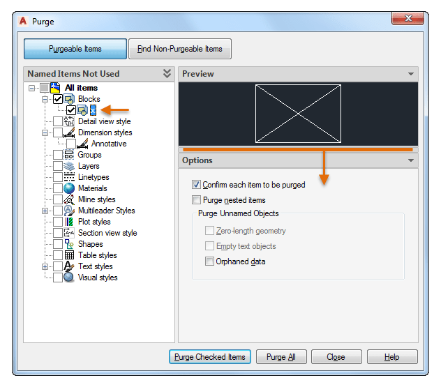
Purge Redesign
The Purge feature has been revised for easier drawing cleanup and organization. The control options are nearly the same, but the orientation is more efficient and a resizable preview area is now available.
You can now purge zero-length geometry without purging empty text objects.
Check boxes in the Named Items Not Used panel provide a way to select purgeable items by category as well as individual items.
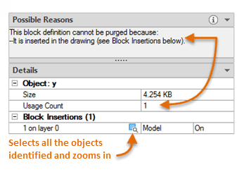
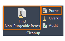
With one click, the Find Non-Purgeable Items button displays additional information specific to why the checked item cannot be purged, which will be helpful in many cases.
For objects that can’t be purged, the new design provides enhanced information as shown below, including the number of objects on which layers, and their impact on file size. The Select Objects button in the illustration below, zooms in on the specified objects that can’t be purged.
These options control whether Purgeable Items or Find Non-Purgeable Items is currently displayed in the Purge dialog box.
New Commands
None.
New System Variables
None.
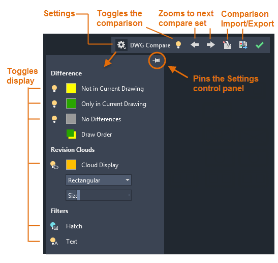
DWG Compare Enhancements
The primary enhancement to the DWG Compare feature is that you can now directly compare and edit the current drawing together with a specified drawing while in the compare state. The changes you make in the current drawing are closely tied to the compared drawing and changes between the drawings are dynamically compared and highlighted.
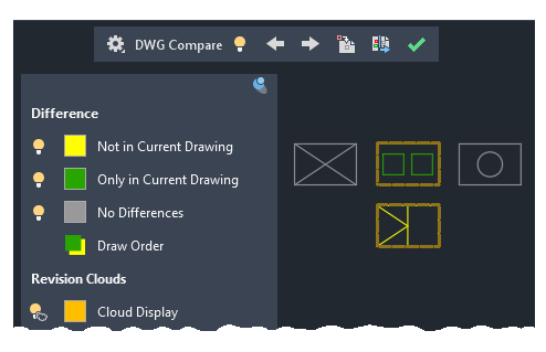
To facilitate direct editing in the compare state, the COMPARE command was moved from the ribbon to a docked toolbar at the top of the drawing area. Most of the options were combined into the Settings control and enhanced as shown. You can easily toggle the comparison from the toolbar and the display of the types of differences from the Settings control.
Also, the default colors can easily be changed by clicking on a color, red to yellow in this illustration, for your preferences or for colorblind-friendly colors.
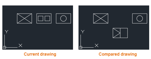
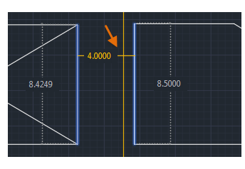
For example, let’s say you need to compare the differences between two highly complex drawings that have been simplified to look like the following:
The result of comparing the current drawing with the compared drawing looks like this:
The change sets are each surrounded by orange revision clouds, which are more clearly visible when you’re zoomed in.
You can import the highlighted differences (yellow) from the compared drawing into the current drawing. If you do so, these objects will now exist in both drawings and will automatically turn gray. Only the objects in the specified area that are not in the current drawing can be imported.
You can also export both drawings into a new “snapshot drawing” that combines the similarities and changes between both drawings. The result of this operation is the same as a drawing comparison in AutoCAD 2019.
The arrow buttons provide a way to step through each change set, automatically zooming in to each successive or previous change set.
Ribbon Access
Collaborate tab > Compare panel > DWG Compare.
New Commands
COMPARECLOSE – Closes the Compare toolbar and exits the comparison.
COMPAREEXPORT – Exports the comparison results into a new drawing, called a snapshot drawing, and opens the drawing.
COMPAREIMPORT – Imports objects from the compared file into the current drawing. Only the selected objects that exist in the compared file and not in the current file are imported.
New System Variables
None.
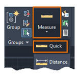
Measure Geometry Option-Quick Measure
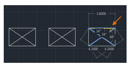
Measuring has become much faster with the new Quick option of the MEASUREGEOM command. With this option, you can quickly review the dimensions, distances, and angles within a 2D drawing.
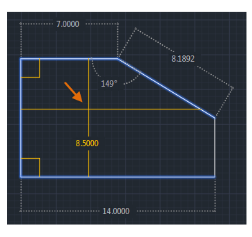
When this option is active, the cursor displays all nearby measurements, both inside and outside the nearest parts of a drawing. The squares displayed at the left side of the illustration represent 90 degree angles.
The distance between the two objects is measured in the illustration below because they’re parallel.
Tip: To avoid quick dimension clutter and to improve performance, it’s best to zoom into complicated areas.
Ribbon Access
Home tab > Utilities panel > Measure/Quick.
Changed Commands
MEASUREGEOM – Adds the Quick option for real-time measurements.
New System Variables
None.
Save to Web & Mobile Enhancements
AutoCAD 2020 includes additional support for AutoCAD Web and AutoCAD Mobile. The enhancements are as follows:
Support cloud connectivity and storage. Depending on what you have installed, the Places list in AutoCAD file selection dialog boxes can include Box, Dropbox, and several similar services.
Xrefs are now included with the drawing files that you save for web and mobile access.
The CAD Manager Control Utility includes a new checkbox on the Online Content tab to disable the SAVETOWEBMOBILE and OPENWEBMOBILE commands. This control has been added for sites that require their drawings to remain within their organization’s network.
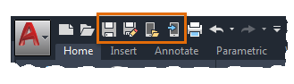
Access
Quick Access toolbar save and open commands:
New Commands
None.
New System Variables
None.
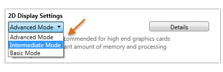
Graphics Configuration
AutoCAD now launches correctly with different DirectX drivers (Dx9, Dx11, or no driver), high resolution (4K) monitors, and dual monitors. In addition, the graphics display settings are consolidated into three modes, which includes gradient hatches and images. The graphics performance setting, Intermediate Mode, is updated to reset several display parameters automatically to optimize your display.
Access
Enter GRAPHICSCONFIG at the Command prompt.
The Graphics Performance dialog box displays, shown in part below.
Use the Same Version of software to Admin your Database
Consistently use the same version of software for all administration work. You can draw/model/estimate/etc using any version. Just make sure your users don’t have administrative permissions on their login. But for administering your database, always use the same version. Here’s why…
You can work in multiple versions of CADmep, ESTmep, CAMduct and even Revit (w/Fabrication Parts) using the same database configuration. In other words, the configuration itself is “Version Agnostic“.
For Revit Fabrication Parts, database compatibility starts with version 2016. The other Fabrication products like CADmep, ESTmep and CAMduct, compatibility goes back to at least the version prior to 2013, before Autodesk acquired the software.
What’s the problem?
You often get new functionality in newer versions of software. Versions of the software that require new data, automatically adds the new data to the database tables. When you only Use older versions of the software without administrative permissions, it ignores that extra data when it encounters it. This is why old versions work with configurations edited with newer versions,
When you try to use an older version to Administer your database, it rewrites those tables but doesn’t see the added data so it gets overwritten. This is why you should stick to the same version when editing your database.
You do not have to use the latest version to maintain your database. You can continue to use an older version for administration. Just don’t use a newer version then go back to the old. You’re perfectly fine to stick with an older version. You just won’t be able to take advantage of new features that rely on added data the new version offers. When you are ready to start using a newer version for Administration, you can make that change anytime but you should also stop using the older versions for administration.
Let’s Demonstrate the Issue
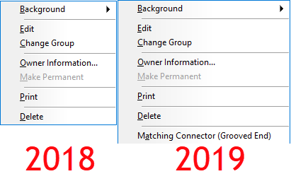
You can watch the video at the end of this article to see an example. In 2019 Autodesk added a new Connector setting for “Connector Matching”. We won’t go into what this does here but you can see in the following image the difference in the right-click menu of connectors.
Fabrication 2019 Added ‘Connector Matching‘
When you watch the video, you’ll see me switch between 2 different versions of ESTmep. I could use any product but ESTmep lets me quickly open and close a database so I can move between versions quickly.
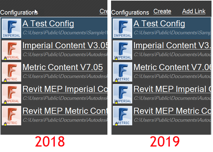
If you look at the configuration icons, you can see which version of software is being used. ESTmep 2019 has all BLUE icons. You can see ESTmep 2018 uses RED icons except the one BLUE 2019 configuration.
ESTmep 2018 has RED Configuration Icons, 2019 uses BLUE Icons
The video starts with “A Test Config” loaded in ESTmep 2019. I select one of the Connectors and change its ‘Connector Matching‘ value. Next, I exit and go back into the same configuration again in 2019 to show the value remains the same. At this point, everything is working as planned.
After exiting the database in 2019, I then switch to ESTmep 2018 and load the same “A Test Config” database. I make a copy of a completely different connector. This is where the problem starts. ESTmep 2018 has no knowledge of this ‘Connector Matching‘ data. Your “Connector Matching” data is over written as soon as ESTmep writes the Connector tables using the format it knows.
Finally, I go back into ESTmep 2019 and verify the data is gone. The default value for the Grooved Coupling’s “Connector Matching” data changes back to “Same“.
When you host a BIM360 Design project, adding members to the project is a common task. If you haven’t done this before, you may notice after typing the address thatBIM360 Design doesn’t seem to recognize it.
When you watch the video, you can notice the blue “Select” button grayed out after typing the Email address. You can type a ‘comma’ (,) after the address to make BIM360 recognize it. You’ll see the Email address converts to a boxed control when you type a properly formatted address.
When you type a comma, this tells BIM360 Design that you’re done typing the address. You can also use a comma to separate multiple addresses. This is why the comma works even when typing a single address.
For years, I’ve shared my Fabrication COD scripts with the industry. These can be used to examine database content using Excel.
Tyler Phillips of Bruner Corporation recently posted a nice article on LinkedIn about using Microsoft PowerBI. His PowerBI dashboard provides a great way to help visualize the data behind your Autodesk Fabrication content.
Simply put, the scripts I share dump property data to multiple CSV files. Tyler used that data for some of the PowerBI data sources. This allowed him to built a dashboard which helps him visualize and navigate the data in a more meaningful way. And better yet, he publish a fantastic article on LinkedIn that explains how to do it.
Microsoft PowerBI Dashboard of Autodesk Fabrication Content
This is a great example of leveraging data from multiple sources. PowerBI help you mash it together to give you meaningful information that’s simple to understand and navigate.
If you’ve ever struggled with ESTmep reporting, just think of the possibilities. By taking the above concept and using it across CSV exports from ESTmep you could easily overcome gaps in estimating reporting.