Don’t use Ancillaries with Breakpoints inside an Ancillary Kit.
Ancillaries are virtual items you can add to your Fabrication configuration. ESTmep users use Ancillaries to help quantify cost and labor. Material quantification for purchasing and/or fabrication is another use for Ancillaries. These are virtual items because they typically don’t affect modeling or coordination. They aren’t even typically drawn yet they are critical to your fabrication as a purchased, fabricated or installed item.
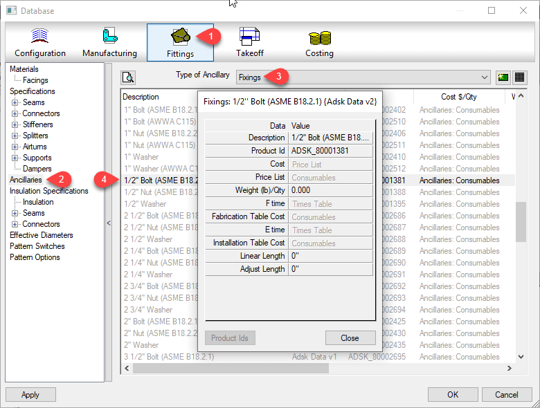
Database view of an Ancillary entry
At times, you many need multiple Ancillaries associated with an item. However the fabrication software typically only allows you to assign a single ancillary to an item or database entry like a connector. For this reason, Autodesk Fabrication includes a type of entry called an “Ancillary Kit” in which you place multiple Ancillaries.
These Ancillary Kits are where you can group multiple Ancillaries that are often used together. A Bolt, Nut and Washers are a good example of an Ancillary Kit.
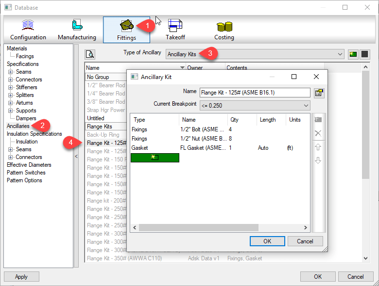
Database view of an Ancillary Kit entry
Ancillary / Kit Breakpoints
Often, Ancillary items are defined by the size of the item they are associated with. As an example, a flange gasket would be different depending on the type and size of flange it’s used with. You can configure an Ancillary to have Breakpoints to reference a different parts depending on the size of the item the Ancillary is associated with.
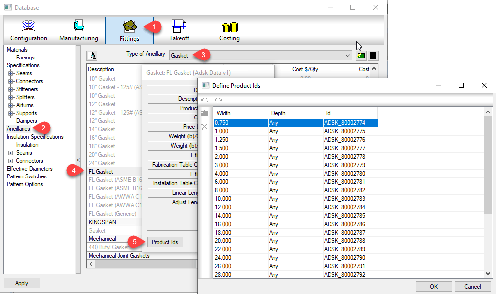
Database view of an Ancillary with Breakpoints
Just like Ancillariess, an Ancillary Kit can also have Breakpoints. Using a flange as our example again, depending on the type and size of a flange, or what it’s connecting to (another flange, valve, pump) it can have different bolt/nut sizes and quantities. You would manage this using an Ancillary Kit with Breakpoints.
Database view of an Ancillary Kit with Breakpoints
Nested Breakpoints
If you watched the example images closely, you can see Autodesk’s own database breaks this Best Practice rule. The rule is to never add Ancillaries that use Breakpoints to an Ancillary Kit. Here’s how to keep that straight…
Yes – Ancillary in Ancillary Kit
No – Ancillary w/Breakpoints in Ancillary Kit
Yes – Ancillary in Ancillary Kit with breakpoints
No – Ancillary w/Breakpoints in Ancillary Kit w/Breakpoints
I’ve not tested Autodesk’s configuration for reporting accuracy. I have enough work managing my own fabrication configuration. However I did create a sample of my own and submitted to Autodesk support. After demonstrating inconsistent results with my sample, their recommended guidance was not to use Ancillaries with Breakpoints in an Ancillary Kit.
Based on testing in other data sets, I would say this is sound advice. Even if you can get it to work, the setup and configuration is less intuitive and confusing. Your Ancillary Kit can reference different Ancillary types using different Breakpoint criteria. The Ancillary Kit could also have conflicting Breakpoint criteria (e.g. Length x Width vs Diameter) compared to the Ancillary.
Keeping this Best Practice can create more Ancillary entries as well as make building Ancillary Kits a little more time consuming. But the results will be more predictable and what’s really happening in your configuration will be more obvious and less obscure. Even where Breakpointed Ancillaries do function within an Ancillary Kit, it’s advised to avoid this where possible.
Use the Same Version of software to Admin your Database
Consistently use the same version of software for all administration work. You can draw/model/estimate/etc using any version. Just make sure your users don’t have administrative permissions on their login. But for administering your database, always use the same version. Here’s why…
You can work in multiple versions of CADmep, ESTmep, CAMduct and even Revit (w/Fabrication Parts) using the same database configuration. In other words, the configuration itself is “Version Agnostic“.
For Revit Fabrication Parts, database compatibility starts with version 2016. The other Fabrication products like CADmep, ESTmep and CAMduct, compatibility goes back to at least the version prior to 2013, before Autodesk acquired the software.
What’s the problem?
You often get new functionality in newer versions of software. Versions of the software that require new data, automatically adds the new data to the database tables. When you only Use older versions of the software without administrative permissions, it ignores that extra data when it encounters it. This is why old versions work with configurations edited with newer versions,
When you try to use an older version to Administer your database, it rewrites those tables but doesn’t see the added data so it gets overwritten. This is why you should stick to the same version when editing your database.
You do not have to use the latest version to maintain your database. You can continue to use an older version for administration. Just don’t use a newer version then go back to the old. You’re perfectly fine to stick with an older version. You just won’t be able to take advantage of new features that rely on added data the new version offers. When you are ready to start using a newer version for Administration, you can make that change anytime but you should also stop using the older versions for administration.
Let’s Demonstrate the Issue
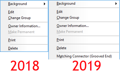
You can watch the video at the end of this article to see an example. In 2019 Autodesk added a new Connector setting for “Connector Matching”. We won’t go into what this does here but you can see in the following image the difference in the right-click menu of connectors.
Fabrication 2019 Added ‘Connector Matching‘
When you watch the video, you’ll see me switch between 2 different versions of ESTmep. I could use any product but ESTmep lets me quickly open and close a database so I can move between versions quickly.
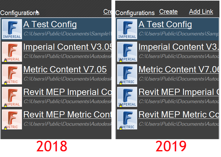
If you look at the configuration icons, you can see which version of software is being used. ESTmep 2019 has all BLUE icons. You can see ESTmep 2018 uses RED icons except the one BLUE 2019 configuration.
ESTmep 2018 has RED Configuration Icons, 2019 uses BLUE Icons
The video starts with “A Test Config” loaded in ESTmep 2019. I select one of the Connectors and change its ‘Connector Matching‘ value. Next, I exit and go back into the same configuration again in 2019 to show the value remains the same. At this point, everything is working as planned.
After exiting the database in 2019, I then switch to ESTmep 2018 and load the same “A Test Config” database. I make a copy of a completely different connector. This is where the problem starts. ESTmep 2018 has no knowledge of this ‘Connector Matching‘ data. Your “Connector Matching” data is over written as soon as ESTmep writes the Connector tables using the format it knows.
Finally, I go back into ESTmep 2019 and verify the data is gone. The default value for the Grooved Coupling’s “Connector Matching” data changes back to “Same“.
It’s not a lot, but there are some improvements in Revit 2019.2 for Mechanical Contractors using Fabrication Parts. Martin Schmid, MEP Product Manager with Autodesk, explains more with some great video examples on the Revit Blog.
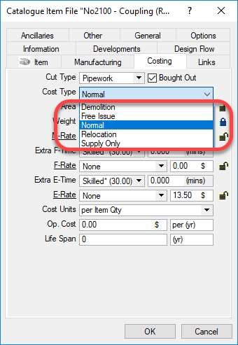
When you build Autodesk Fabrication content, you may have noticed one of the properties “Cost Type“. You can see this setting is shown in the following image.
If you do some searching online, you may run across an explanation for some but not all. As Autodesk explains in it’s online help….
Normal – Reads the Material, Fabrication, and Installation tables to generate costs of all materials, fabrication labor and installation labor.
Supply Only – Reads the Material and Fabrication tables to generate the same costs of material and fabrication but NOT installation. (You’d typically use this if you are fabricating for others outside your company.)
Free Issue – Reads only the Install table when calculating costs.
This leaves two remaining values that can be set. These are not documented by Autodesk. These two serve the same purpose…
Demolition – Used as a filter for Labor table value sets
Relocation – Used as a filter for Labor table value sets
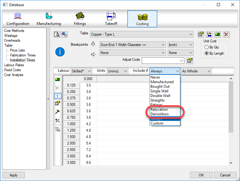
Using these values would allow you to build a labor table for relocation that would include uninstall and reinstall time. You could also use the demolition value to build a labor table for removal only of an item.
While you would think these only would apply to an install table, these filter values are also available for the fabrication table. At the very least, this opens up the possibility of using it in creative ways to serve whatever purpose you like.
After a very brief appearance toward the end of October, the Fabrication updates for 2018.3 and 2019.1 are back on line as of today.
Unlike previously speculated, they were not removed due to issues. They were intended to be released later but were inadvertently released early. If you happened to have them from their initial release, you don’t need to download the update again, the build numbers did not change. However, the PDF documentation of fixed issues on some of them did get more information listed in what was fixed. You can review all the issues addressed here…
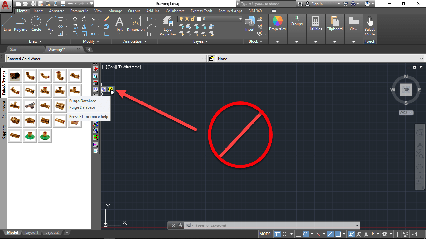
If you’re running 2019.0.0 versions of Autodesk Fabrication, you should be aware of this critical issue.
When using purging the fabrication database, the command will delete all of the content on your service templates leaving them with no buttons or content.
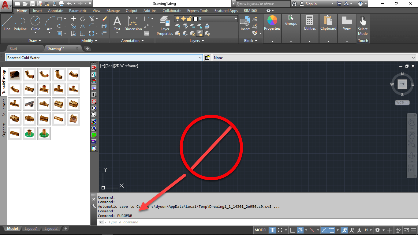
There are several ways to access this command. In CADmep, PURGEDB is accessed from the toolbar…
You can also type PURGEDB from AutoCAD’s command line.
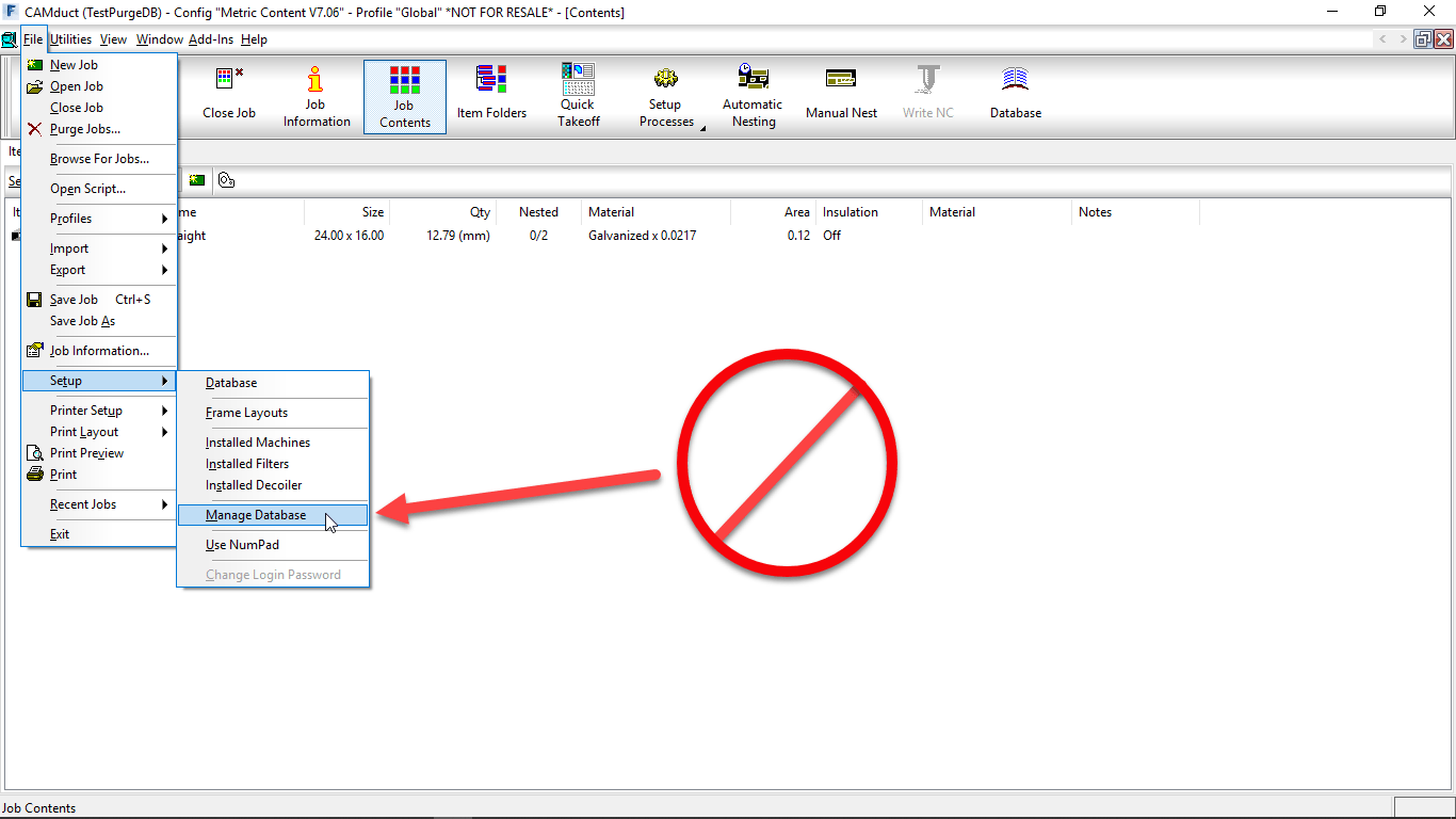
From ESTmep or CAMduct, the functionality is accessed from the FILE -> Setup -> Manage Database menu.
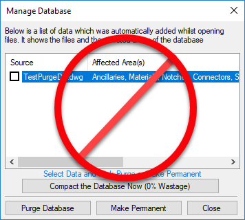
The Purge Database command itself displays the following dialog…
Again, in version 2019.0.0 versions of fabrication products, this will remove all content from all of your service templates. Do NOT run the command. Want to see for yourself what happens? Watch this Screen Capture…
This will only be a risk if you are logged into your database with Administrative privileges. In the event you have had this already happen, the only way to restore your services is to restore them from a backup of your database or to rebuild them all manually.
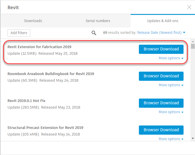
Autodesk released the Revit Extension for Fabrication 2019 on May 25, 2018. This extension (Add-In) will allow you to Import and Export Autodesk Fabrication MAJ files into or from Revit 2019. You can access the extension from the Autodesk Accounts portal or from the Autodesk Desktop App.
Make sure ALL of your ITM content has a Database ID assigned to it.
A database ID is a unique identifier for content. There should be a single Database ID for any ITM that is NOT Product Listed. For Product Listed ITM’s, there should be Database ID for each entry in the product list.
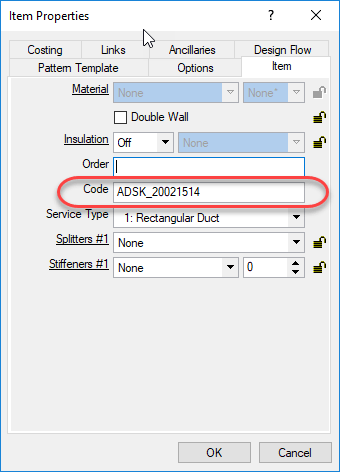
For ITM’s that are not product listed (typically fabricated sheet metal fittings or other content where the ITM only represents one size, you can put the Database ID in the “Code” field of the ITM Properties as shown in the following image…
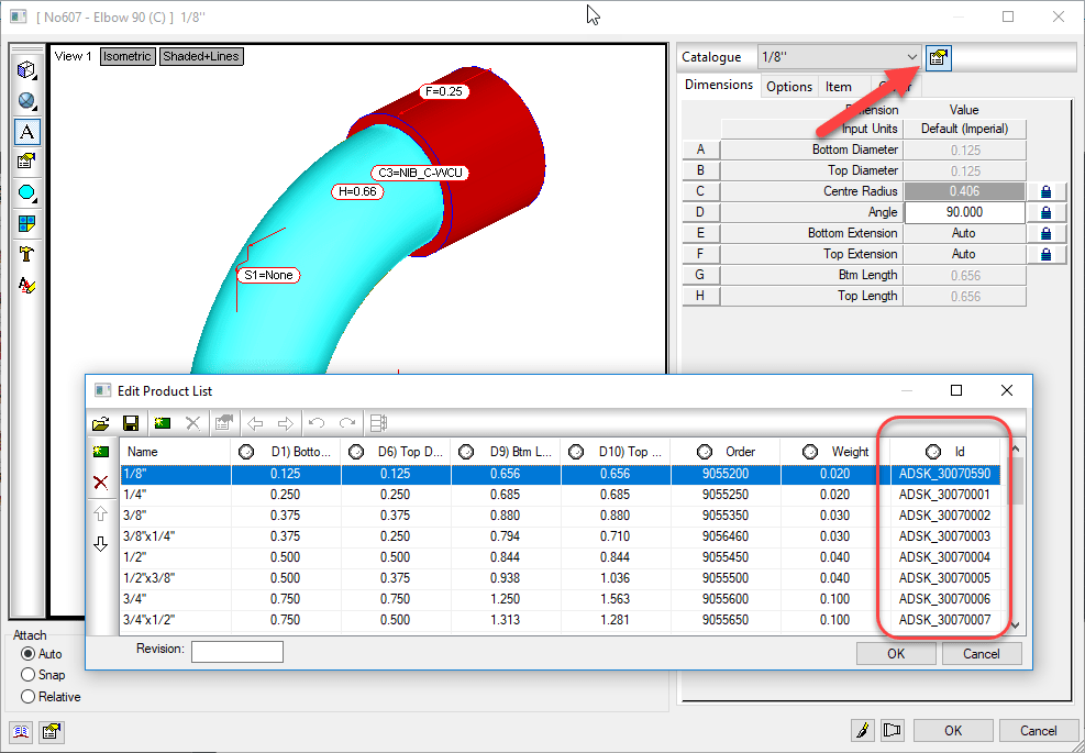
For ITM’s that are Product Listed, the Database ID should be in the ID column of the Product List. When you place an instance of a product listed ITM in your model, you select a size from the product list, When you select that size, the Database ID associated with that size it automatically entered into the Code field of the ITM Properties like shown earlier, The following image shows the Database ID column in a Product List…
Why Use A Database ID?
The Database ID is a useful component to managing an Autodesk Fabrication configuration. This Database ID can be referenced by other aspects of Autodesk Fabrication should you choose to use them. The Database ID is what can link your content to….
Price lists
Fabrication Labor
Installation Labor
Product Information (ProdInfo)
Even if you don’t use ESTmep for estimating and don’t want to use the Price and/or Labor features of the database, Product Information is tied to the Database ID and is used to store additional meta data about your content like Manufacturer, Size, Description, etc. Even if you’re not using ProdInfo now, it’s still a good idea to use Database ID’s because adding them to the content is the most time consuming part. It’s easy to add them when building content, more cumbersome later after the fact. If all your content had Database ID’s assigned, it’s much easier to implement ProdInfo, Price and/or Labor later down the road.
The following Video shows how to access the Database ID of Product Listed and Non-Product Listed ITM’s. It also shows you 2 different sizes of a product listed ITM in a drawing and how Autodesk Fabrication automatically assigned the Database ID from the Product List for the corresponding size into the Code field of the ITM Properties.
Key Database ID Takeaways
Here’s a few pointers when working with Database ID’s:
Each Database ID should be unique and not assigned to other content or sizes.
Managing Database ID’s using a spreadsheet or other database makes managing them much easier.
Your database ID can be anything you want but should have some sort of naming standard associated with it.
Your Database ID Naming standard can be as simple as a prefix followed by incremental numbers to something complex with special codes and formatting to indicate other aspects of your content. (e.g. Valves, Pipe, Sheetmetal, etc)
You can use Autodesk or other Vendors ID’s if they already have them assigned and use your for anything you create or replace them all with your own company Database ID’s if you are particular about naming standards,
Don’t reuse ID’s if the content that once used them is now obsolete. Legacy/Archive drawings still reference these numbers. Simply flag them as being obsolete in the Spreadsheet you are managing them with.