Autodesk Fabrication – Profile Error w/UNC Paths

If you use UNC pathing to get to your Autodesk Fabrication Database, you might find issues when trying to create Profiles if you use them. UNC pathing or (Universal Naming Convention) is where you specify a server and share vs a drive letter. You can see below, the Metric Autodesk Fabrication Configurations is using a UNC path…

When using this configuration, you can create a profile from the File drop down menu in ESTmep and CAMduct or by typing MAPPROFILES in CADmep.

Creating New Profiles

You go to create a new profile by clicking the Green button.

From here, the New Profile dialog starts with the default name “Untitled”. Notice also, the double leading forward slashes before the server name in the UNC path. (Yes, ‘little-stink’ is the server name)

When you start to type a profile name, the leading forward slashes get stripped. This is likely a bug. You can see that in the following image…

If you click the OK you’ll get an error that the profile can’t create the required folder.

However, the fix is easy. If you just add the leading forward slashes again, you” be able to create the profile.


It may be easier to see from a video. You can watch the process here…

Autodesk Fabrication: Best Practice #14

Eliminate All Broken Service ITM’s

Your services should not have broken links to ITM’s. Not only is it sloppy database management, it can slow performance of your database.

Use the Path Repair Tool to find (and fix) broken links in your services.

Right-Click and empty area of your Service Palette and select Path Repair Tool.

When you run the Path Repair Tool you’ll be asked to select a mapping file. You can click cancel and the tool will continue on. When it’s done, you’ll have a list of broken paths copied to the Windows Clipboard that you can paste into a file.

From this file, you can then create a mapping file. The mapping file is merely a text file in the format….

OLD PATH/NAME,NEW PATH/NAME

So the data you paste from the clipboard is good starting point, it lists all the broken paths. There may be duplicate paths listed if the path is used in multiple service templates. It’s ok to remove the duplicates.

Simply ass a comma after the broken path name and enter the new, corrected path. Once done, you can save the file and use it when you run Path Repair Tool again. It’ll then go and fix all those broken paths.

NOTE: This repair technique does NOT work if you have commas in your folder or file names. (See Best Practice #11)

Autodesk Fabrication COD Object Model

I’ve added graphics to better illustrate the Autodesk Fabrication Object Model for COD Scripting,

If you write COD scripts for CADmep, ESTmep or CAMduct, this can help you better understand how the various properties and objects are structured when you write your code.

If you want to learn more about Fabrication COD Scripting and how to use these resources, register for MEP Force 2021 and look for my Fabrication Scripting sessions.

You can find links with the other Fabrication COD Language Reference items here…

Fabrication COD Scripting Language Reference

Individual Object Models can be directly accessed here…

There’s also a link to a printable PDF of the Object Models….

Autodesk Fabrication 2022 Updates

Autodesk Fabrication 2022 marks a decade that I’ve been updating various documentation for the program. As usual, in recent years not a lot has changed but there are a few changes. Here’s a review of the changes for the data I track…

Script Library Updated / Enhanced

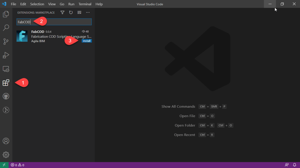
COD Script Library was updated for JOB and LIBRARY Scripts. You can download them for free here. Here’s a summary of changes.


Script Consolidation

In the past, there were 69 to 75 COD Scripts to export all the various properties to separate TXT files. Properties that have multiple entries per ITM like Connectors or Seams are still exported to separate files because the data columns don’t line up between them and there are multiple lines per ITM.

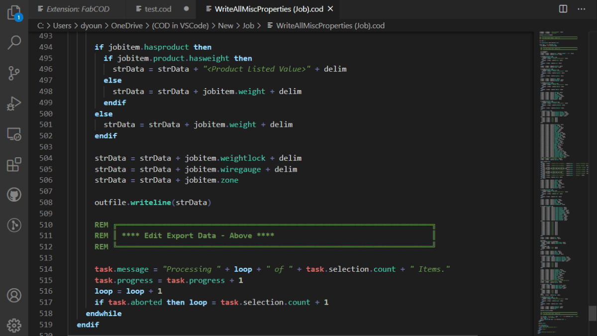
All other properties where it’s a single property per ITM like Spool or Material have all been consolidated to a single script and single TXT file. The WriteAllMiscProperties(Job).cod and WriteAllMiscProperties(Library).cod scripts are where you can extract all other properties so no matter what combination of properties you want, there’s less data files to sort through or scripts to run.


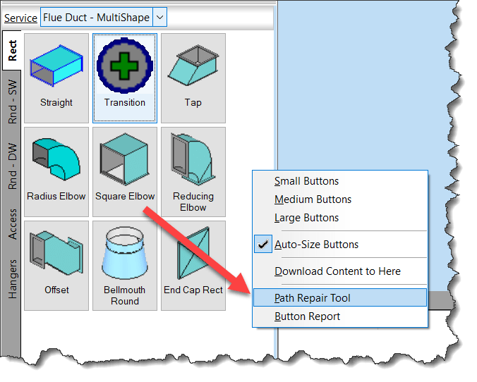
Improved Script Properties Display

The properties scripts were displayed script settings before running the script. They still are but additional properties are displayed where appropriate along with some additional properties the scripts now support (both covered later). In addition to the additional items, you’ll note that clicking the No button no longer cancels the script. Instead, clicking No takes you to the Advanced Configuration (also covered later) where you can change some of those settings.


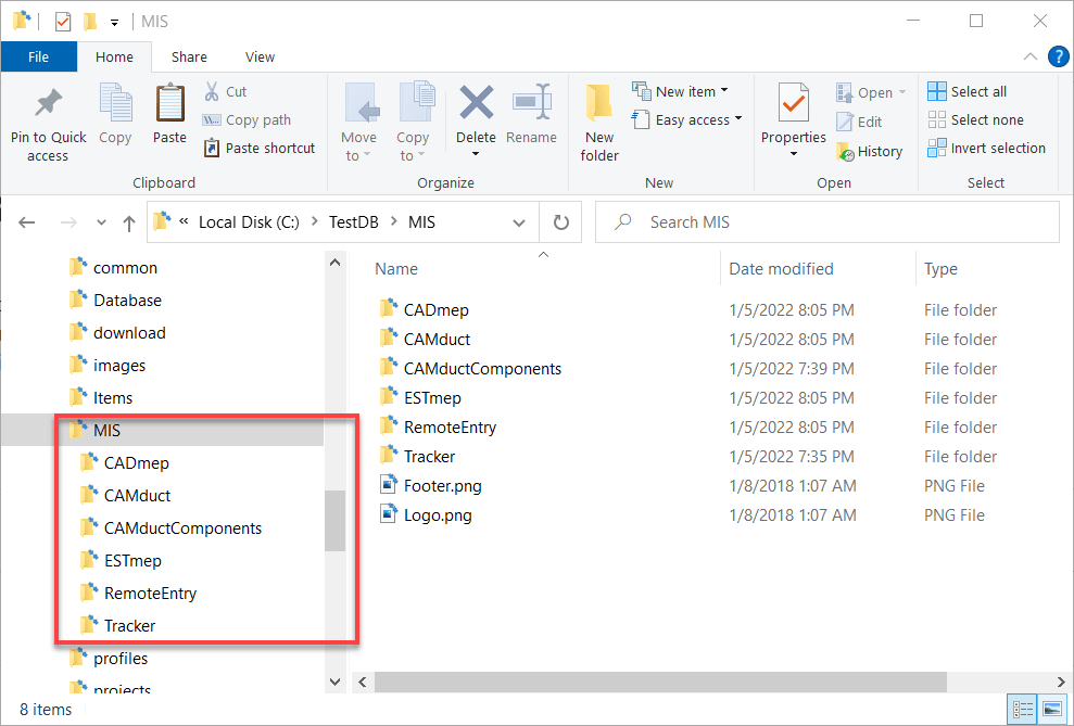
Advanced Configuration – Scan Folder (LIBRARY Scripts Only)

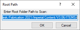
By default, the script looks to the root of your ITM Library folder of your database. This value can now be changed to point anywhere else. You may want to point to a folder of ITM’s outside your Configuration if that’s where you store your ITM’s. You can also scan further down the folder structure so you can perhaps skip exporting Duct ITMs but instead scan and export Piping ITMs.

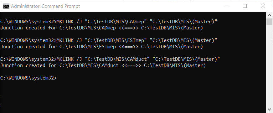
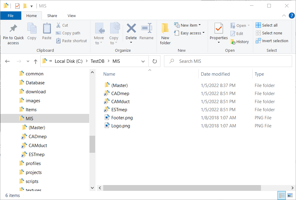
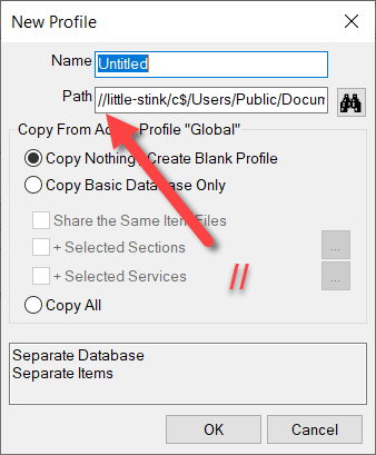
Here’s what this looks like. Note that the path may use forward slashes ( / ). You can however paste a new path that uses backslashes ( \ ) and it should still work. There’s no option in COD Scripts to allow you to browse to a folder so make sure you type or copy/paste carefully.


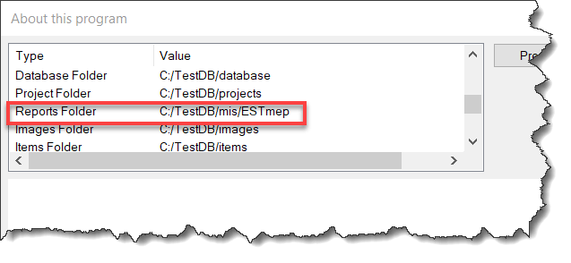
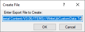
Advanced Configuration – Export File (JOB and LIBRARY Scripts)

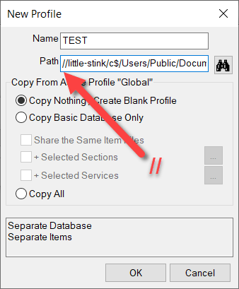
Similar to the Scan folder configuration, you can now also change the default export file name and location. Specifications for specifying paths are the same as above.

Also note that while you CAN specify “CSV” as the file extension, I recommend using “TXT“. When Excel sees a CSV file, it just opens it without giving you the ability to specify how data is interpreted. Using a “TXT” extension makes Excel prompt you for “How” the file should be read like which character is used as the delimiter or defining which columns are Text vs other data types.

Some numerical data or values can be interpreted incorrectly by Excel if you don’t explicitly tell Excel to treat them like Text. A good example of this is the size 1-1/2″ or 1-1/4″. Excel thinks these are dates and will display them as 1/1/2012 or 1/1/2014 respectively if you don’t explicitly tell Excel to treat them as Text. Using that “TXT” extension on the export file is a safe guard against this issue.

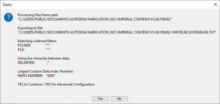
A lot more detail that you likely wanted but hopefully it’s helpful, here’s what that looks like….

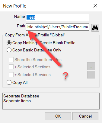
Note you may see an extra slash character between the path and file name. This is can happen if your MAP.INI (Edit Configuration Utility) includes or doesn’t include an ending slash. I may add code to clean this up later but COD Scripts and Fabrication seem tolerant of this extra slash so no need to worry about it (or edit it out if you like).


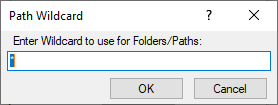
Advanced Configuration – Folder/Path Wildcard (LIBRARY Scripts Only)

Instead of editing the folder you’re going to scan, alternatively you can specify a wildcard to use to limit which folders to export data from. As an example, you could specify *WELDBEND* and properties will only be extracted for ITM’s within folders containing the name “Weldbend”. Wildcard specification is not CaSe SeNsItIvE. By default, the wildcard is ( * ) to extract from all folders. Here’s what that looks like…


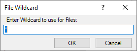
Advanced Configuration – File Wildcard (LIBRARY Scripts Only)

Just like the Folder/Path Wildcard specification, you can specify a wildcard for which ITM files to extract properties from. As an example, you could enter *PIPE* and you would export only from ITM files that contained the work “Pipe”. Again, the wildcard is not CaSe SeNsItIvE. You can use both Folder and File wildcards to very narrowly specify your data export scope. Default wildcard is an ( * ) to extract from all ITM files. Here’s what that looks like…


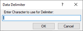
Advanced Configuration – Delimiter (JOB and LIBRARY Scripts)

Data exports by default use a Comma ( , ) to create a Comma Separated Value file. If your Fabrication Database uses commas in folder names or ITM file names this can cause data fields to shift in Excel when opening the export file. If this is the case for you, you can specify a different character to use to separate the data fields in the export file. The Pipe ( | ) character is always a good “rarely used” character for this purpose.

As a side note, it’s not a good practice to have commas in folder or file names. You can read more about that here. This option is really here in case you’re stuck with commas and haven’t fixed them yet.


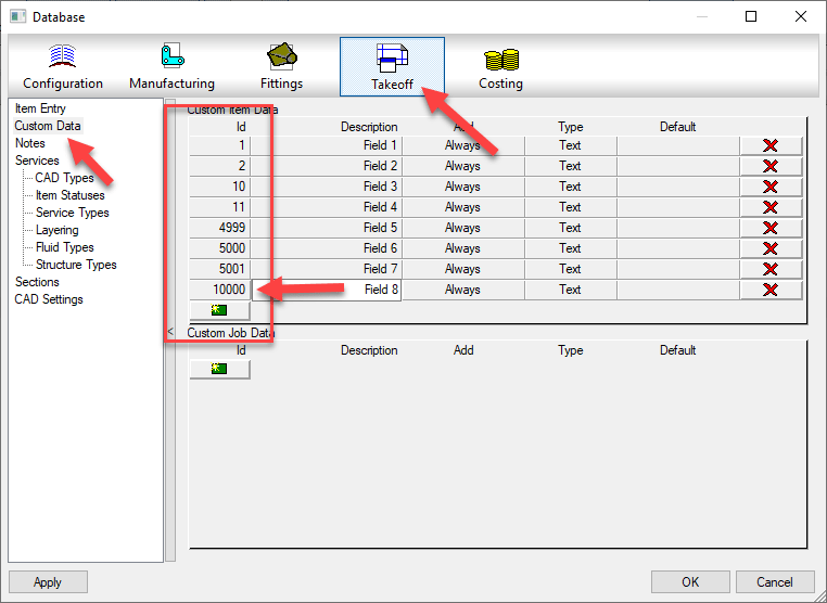
Advanced Configuration – Max Custom Data Index (Only Scripts that export Custom Data)

Only used for scripts that export Custom Data, you can specify the maximum Custom Index value. Unfortunately, COD scripts have no ability to determine how many custom data entries you have or which index numbers are used without jumping through some hoops. To work around this, you need to specify the maximum Custom Data Index value. The script will then loop through all those numbers and find which ones contain values and remembers them. It then exports only those custom index values so that the script runs efficiency.

By default the script uses 5000 as the maximum index number. But as you can see from the below example, the maximum index number is 10000 so we need to specify that. We look at all 10000 possibilities (it goes fairly quick) and takes note that there’s only 8 indices used and then extracts only those 8 from the ITM’s. In the past, the script would loop through all 10000 for each ITM really slowing things down. Now, even if your largest number is 6 or 7 digits (not recommended) the script will still be fairly quick.

Here’s what that Delimiter Character configuration option looks like…


Summary

In the past, if you didn’t like the export files names, where they went, or wanted to change the scope of which files or folders you extract data from, you could have always changed the COD script code yourself. You now shouldn’t have to. Hopefully this makes running these scripts a little more flexible and user friendly.

COD Script Extension for VS Code

If you write COD Scripts for Autodesk Fabrication, take note. There’s now an Extension for Microsoft Visual Studio Code (VS Code) which is Microsoft’s free code editor. If you use Notepad or Notepad++ to edit your code today you may want to consider switching. The COD Extension has some really nice features. Color coding of your code is the most obvious as shown below. However, there’s a lot more than just color coding. Features like Auto-Complete, Folding Sections and Dimension/Option Picker are nice additions in addition to a lot more robust documentation.

Installing The Fabrication COD Extension

If you don’t already have it, you can download and install VS Code here…https://code.visualstudio.com/. Once installed, go to the Extension section, type FABCOD and click the Install button.

Extension Summary

Once you’ve installed the Extension, you can review a summary of extension details here…

From here, you can review a couple of the key features and their keyboard shortcuts….

VS Code Feature – Mini-Map

Not a feature of the extension, but one reason VS Code is a nice editor is the Mini-Map which helps you visualize where you are your code.

FABCOD Extension Feature – Folding

One of the features the FABCOD extension exposes in VS Code is the ability to collapse/expand sections of code for Looping and Conditional function and other areas. When you move your cursor to the left margin, you see symbols that activate this functionality called Folding.

In addition to Folding sections of code, you can create your own areas of code to collapse/expand. These are Folding Regions and can be inserted (or typed manually using the proper syntax) by highlighting the code and pressing CTRL+SHIFT+/.

FABCOD Extension Feature – AutoComplete

Auto-Complete is another core feature of any code editor. VS Code’s Auto-Complete features is leveraged by the FABCOD extension. You’ll need to be editing a saved file with a COD file extension so the VS Code extension knows which code extension to use.

ABCOD Extension Feature – Hover Tips

If you hover over known functions/properties and their context can be determined, VS Code will display a tooltip for the function you’re hovering over. This can be a great way to learn coding as it’ll help you with the syntax.

FABCOD Extension Feature – DIM / OPTION Picker

One of the best features of the FABCOD extension is the ability to get suggestions for the Dimension (DIM) and Options. You can activate the DIM picker with SHIFT+F1 and the OPTION picker using SHIFT+F2 keyboard shortcuts. When using these features, you are presented with an edit box. You type the CID/Pattern Number you’re interested in and press Enter. You are then given a list of Dimensions or Options you’re interested in. It’s not fool proof because some patterns have variable DIM/OPTION values but it seriously helps none the less. Take a look here…

FABCOD Extension Feature – Additional Help

Sometimes you need added help for a function. The FABCOD extension is an open source project on GitHub (https://github.com/AgileBIM/FabCOD). This project contains added help for every function and property and is Auto-Generated and updated as the extension is developed. You can access this help from any of the popup ToolTips by clicking on the BLUE hyperlinked text.

FABCOD Extension Feature – AutoCAD Launcher

One of the other neat features of the FABCOD extension is the AutoCAD Launcher. Pressing F5 in the editor will initiate the script in CADmep. Simply Alt-Tab to AutoCAD and press enter. AutoCAD and CADmep must be loaded at the time for this to work. Due to Autodesk’s limitations in their API’s, this functionality does not work with ESTmep or CAMduct.

VC Code FABCOD Extension – Wrapup

There’s a lot more to VS Code that I won’t get into here. I’ve only covered the highlights of how it and the FABCOD extension can be used to help edit COD file in Autodesk Fabrication. As it’s an open source project, there’s instructions on how to become involved if you have the coding skills. You can also just head over and log issues or suggestions. (https://github.com/AgileBIM/FabCOD)

Fabrication Job Contains No Parts – Possible Fix?

Have you ever tried importing an MAJ into Revit and received the following error….Fabrication Job Contains No Parts.

There’s a lot of reasons this can occur and it’s NEVER because there are no parts. So much for Autodesk’s QA/QC and Error checking.

You may see this most commonly because parts used in the model contain data that’s no longer in your database. You’ve likely noticed from time to time database entries with curly braces around parts of the name like the following…

This happens when an entry in the database is used by an ITM but the database entry itself later gets deleted. Information is cached within the ITM so when it’s accessed, it creates a Proxy entry in your database if it was missing. Within the {Curley Braces} is the name of the object that created the entry.

While CADmep, ESTmep and CAMduct handle this fairly gracefully, Revit on the other hand does not. When it attempts to load an MAJ, it sees these entries and notices they’re missing from your database and prohibits you from importing the MAJ file. Revit thinks the database doesn’t match the MAJ and stops you cold!

A Possible Fix

If this is cause for the import error, you can use the following COD script to potentially work around the issue….

Take the following script and run in in CADmep, ESTmep or CAMduct. You should be logged in with Administrative Permissions while doing this. This script isn’t fixing Revit or the MAJ. What it’s doing is loading ALL the ITM’s from your Database Library into memory.

The process of loading all these ITM’s into memory creates all these proxy entries in your database. This way, when Revit attempts to import the MAJ, the data associated with those ITM’s are most likely present in your Database configuration. In many cases then results in a successful import of the MAJ.

If the Revit file you are importing the MAJ into already points to a Fabrication Configuration, you should reloaded the configuration FIRST before attempting to import the MAJ.

If for some reason this process still doesn’t work, verify that Revit is reading from the same database location as the version of CADmep, ESTmep or CAMduct where you ran the COD script.

In the event it still doesn’t work, there may be other reasons for the failure but this is often the most common, especially with MAJ’s created recently.

If it does work, you’ll want to use the other scripts I provide on this site to help analyze your database. You likely deleted those database entries in the first place for a reason. You either didn’t realize they were needed, or you didn’t know where they were used to repoint those ITM’s to a proper substitute. Those scripts can help you find which ITM’s use which database entries.

Hope this helps.

Autodesk Fabrication Scripting – Did You Know?

In the list of COD Scripting updates I just posted, there’s a couple undocumented functions that have been on my list to explore for more than a few years. I’ve finally gotten to them and figured out what they do.

I won’t comment on how long it took me to actually explore what I had listed in my “To Research” list for years other than to say, Procrastination is a Virtue for those with no Patience.

So without further delay…here you go….


Output Function

This first one is the OUTPUT function. You can call it a couple different ways, with and without parenthesis just like the DEBUG function. It doesn’t really seem to matter. It’s really kind of a worthless function in my opinion.

Not only does it only work in CAMduct and ESTmep (not CADmep) it really isn’t that helpful. It just outputs a message to the Console window. I was initially hopeful it would allow me to “script” some of the secret Console command but no such luck. It’s just a message.

You can see in the COD Code editor the below with both syntax examples…

When you run the script, it’ll call up the Console and display the text you specified. You can see from the following example, it doesn’t even space the text when you call it multiple times. Even tried embedding a Carriage Return in the string and still no luck automating via the Console.


Breakpoint Command

The other command is much more helpful and something most folks don’t know about. I have run into a couple now who knew but most it’s not known. I wish I knew years ago…it’s actually a small step closer to what you’d expect in a modern IDE (Integrated Development Environment).

The Breakpoint function calls up the panel on the right. It displays the values of all your variables. You can see how the value of the “z” variable is displayed. When you hit a Breakpoint, code execution stops until you hit the green arc’d arrow. Code execution then continues until you get to the next Breakpoint if any.

You can access the COD Script editor in CAMduct or ESTmep using the FILE pulldown menu. You can also use the editor in CADmep but unfortunately, there’s no way to display it without writing intentionally wrong code to cause your program to fail and display it. You can then use the editor like you do in ESTmep or CAMduct.

One thing to note, BREAKPOINT only appears to work when you execute code from the Script Editor. If you call it from AutoLISP using (executescript “myscript.cod”) or the EXECUTESCRIPT command in CADmep or by right clicking in your Takeoff items in ESTmep or CAMduct, it runs without stopping your code. This means you can leave the breakpoints in your code and edit/debug via the script editor but not have to remove them when executing them un a production setting.

Digital Transformation for the Average Contractor (Part 1)

There’s a lot of buzzwords in the construction space. Digital Transformation…Industrialized Construction…Machine Learning….Generative Design…Augmented Reality…Drones…Robotics….and the list goes on. So what do you do? Today? Tomorrow? Next year? What actions do you take to prepare for a an unknown future? All while managing the challenges of your current projects, staff, backlog and cashflow.

I use the mechanical engineering/contracting industry in my examples. However the essence of what I’m about to say is applicable to almost any contractor. If you don’t have an unlimited budget, time and/or resources, knowing how to prepare for an uncertain future in the heat of battle can be alarming.

But it doesn’t have to be. You don’t need a crystal ball. You don’t need unlimited overhead and staff to properly prepare yourself and prevent yourself from becoming obsolete from business disruptors. What you need is a good plan. A plan that helps you understand what’s happening, why it’s happening and most importantly how to make the correct turns when you’re not sure exactly where you need to navigate.

The problem…

The contracting business is changing. This is creating a few big challenges to maintaining profitability and efficiency. To survive, we need to tackle these changes head on. Don’t worry, it’s not that hard.

What’s Driving This?

A lot of things are driving these changes, most of which can be grouped into one of two categories. The following lists outline some of the major trends and shifts occurring.

Current trends contributing to “Industrialized Construction”
“Technology Evolution” is driven by several changes.

If you look at any of these trends individually, that all seem obvious. Not only obvious, but it’s hard to argue that any of them are negative or harmful. In fact, they all seem like good things. And they are. But when they’re all happening in unison, all these “good things” are creating a lot of the problems the industry is currently experiencing.

The Chaos of Today

To help manage these disruptions, it’s helpful to understand what’s happening today. Below shows an example of today’s workflow. Most groups work in silos. As they work and create more data and information over the duration of a project, they start throwing it over the fence to others within an organization. Meanwhile, other parts or the organization throw data to them.

Existing project workflows…Separate groups and processes throwing data at each other.

For most this feels like we’re juggling a ball, an egg and a chainsaw. And while we’re juggling we’re also simultaneously in the middle of a game of dodgeball.

So what happens when…

  • We forget to throw data to others
  • Too much / too little information is thrown
  • We don’t catch data thrown to us
  • Too much / too little information is caught
  • We miss the catch or forget to throw
  • Information is caught or thrown early / late
  • We loose information
  • Information was unclear
  • We throw or catch data to fast / slow
  • Data is obsolete or unapproved
  • We get duplicate data

The Solution for Tomorrow

To combat these problems, we need a new process. The below is what we really want. A single stream of data everyone accesses. With this model, you don’t give anyone data, they inherently have access to the data you have which they need. It’s not a copy of the data or a report of the data. It’s access to the source data. Now, when someone needs information, they have access to it.

New project workflows…We all share in a pool of data.

Throughout the construction process, because our data is less fragmented, it’s easy to warehouse. This allows you to better inform design by pulling the historical data from the service group. Sales can now leverage this data to explain the lifecycle savings when your bid may be higher. In reality, any data from any phase can more readily be accessed from any other phase. Quality of the entire process improves when this happens.

A New Technology Stack

This “Future” process is very likely a utopian state we can never fully accomplish. At least not in our lifetime. But that doesn’t mean we can’t get closer. This doesn’t mean we can’t take a more thoughtful and meaningful approach to the solutions we use. The fact is we can. We may still have to use technology we would rather not. Things we can’t integrate as well as we’d like. But we can get closer.

The following are examples of a technology stack portfolio. Key technologies thoughtfully selected which form the backbone of your digital process.

Example of a “Microsoft / Autodesk” based Technology Stack.
Example of a “Trimble” based Technology Stack.

These are just two examples. You don’t have to follow these examples. Your technology stack may be mixed or match differently. You may even have different solutions than those shown in the example.

In these examples, we could use Building Data with Stratus, or Autodesk Fabrication with MSuite. Stratus and MSuite are both model based production management systems. They can both leverage your BIM platform and your BIM content and integrate with your company’s back end ERP system. For a mechanical (or electrical, general, etc.) contractor you can look at a more simplified representation below.

A good “Generic” Technology Stack Model.

Again, your model may differ. You may have two or three circles. The names in those circles may be different. But you shouldn’t have six or seven or twenty circles. It’s important that you put thought into how these systems can be used and work together. It’s also important that you understand their limitations.

This isn’t to say you don’t use a lot of additional applications. But they shouldn’t be major data stores without connectivity to some of the pillars in your technology stack. Ideally they’ll connect to one of the existing pillars but not be a major pillar in themselves.

Wrapup

This wasn’t really intended to be a roadmap. It’s more of a vision. Something you should be trying to achieve with careful thought and consideration. There’s no magic formula or combination. Nothing you should blindly copy and follow from others. Your technology stack needs to match your organization. The speed and effort to put it place based on your company culture and organizational readiness.

Regardless of how long it takes, the important thing is you’re working toward that vision. We don’t know what the future will bring in our industry. Some things will never change while others may abruptly disrupt your business. No matter what changes are forced upon you, the less impactful these changes will be the closer to this model you are. When required to, you’ll be better positions to respond in an agile manner.

In my next article, I’ll cover some things you can start doing right now that can help prepare you to implement this new model.

COD Script Updates – 2020.07.08

I’ve made a couple updates to the Autodesk Fabrication script libraries. If you use them, you can download updated versions from here.

Scripts have been updated to include the Connector Material property found on CID/Patterns 522, 1522 & 2512 as shown below…

This property is intended to be used by a connector to specify a alternate material the connector can connect to. This allows a coupling to connect to alternate materials such as with transition couplings.

Credit for discovering the COD function to extract this property goes to Liz Fong at MacDonald Miller Facility Solutions in Seattle, WA.

Note: This property has also been added to the list of COD Item Properties located here.

Scripts Updated

  • Debug Scripts
    • Debug ITEM Connectors.cod
  • Job Item Scripts
    • WriteAllConnectors (Job).cod
    • WriteAll_Props (Job).cod
  • Library Item Scripts
    • WriteAllConnectors (Library).cod
    • WriteAll_Props (Library).cod