I’ve updated the Fabrication COD Script Libraries. You can find them here. There’s a few things you’ll note…
Database Table Export Scripts
I’ve added a library of DATABASE scripts. These scripts will export to a file the names of the entries for select tables in the Autodesk Fabrication Database. For all practical purposes, COD scripts can’t read from the database tables directly. They can only read and write properties of ITMs. However, there’s an exploit that can be used on a few database tables that allow you to iterate through them and step through the entries, assigning them to a Proxy ITM. Using this approach, we can export rudimentary table data limited to group/name.
This technique was discovered via the work of Christopher Kelly at Infinite CAD Solutions who years ago posted a COD script that iterated through the Connector table in a search/replace function that he posted to XtraCAD.Com.
Export Data Wrapped in Double Quotes ” “
Data fields are now wrapped in “double quotes”. This is done so that entries that may contain a comma are no longer split by Excel thinking it’s the start of a new field. This means that if your data contained a comma, you no longer need to use the advanced functionality to change the delimiter of the export to something other than a comma.
Note: I still highly recommend avoiding use of these commas in data field values as Autodesk does not do a good job of handling these in it’s own exports.
Embedded Double Quote Handling
Text that may contain double quotes (“) are now expanded to “double double quotes (“”). This helps Excel process them as actual parts of the data field and not wrappers around a field. Again, this improves data handling for text fields that happen to contain characters also used by CSV files.
Note: I still highly recommend avoiding use of double quotes in data field values as Autodesk does not do a good job of handling these in it’s own exports. If you want to simulate this look, use two separate single quotes.
Fraction Support
Fields like Size and Description can often contain fractional data which Excel loves to convert to dates or other characters. I’ve prefixed these fields with an equal sign (=) which forces excel to treat them as Text and not automatically try to interpret their data type and convert them.
CSV Exports vs TXT Exports
In the past, these scripts exported to a TXT file to force Excel to open the import wizard and allow you the ability to specify which fields were text. As a result of the above changes, this should no longer be necessary so the export files will now be CSV file extensions. This should now allow double clicking on them open them in Excel without splitting strings that contain sommas or double quotes or converting fractions to dates. If you run into properties still prone to Excel automatically converting them, please let me know.
2022 and Earlier Scripts NOT Updated
As time progresses, so should the version of software you use. As such, I’m no longer actively updating the old scripts to include the above changes. They’re still there to download should you need them. And you can easily download both and use a file compare utility to find the differences and update them yourself.
As there’s a LOT of small changes to these scripts. As such, it’s certainly possible I mistyped something and one produces an error in certain data sets. If you run into an issue, please let me know.
There’s a bug that crept into Autodesk Fabrication versions that prevent some COD scripts from running. Any Script that accesses the Item Product list [item.product / item/product.*] will likely fail in the initial shipping version of 2026 and any prior Fabrication version’s update that was released on May 21, 2025.
Here’s what that error looks like when you attempt to run one of my scripts. The code you run may be different but you’ll see a “Simple Variable Not Expected” error in the script and the highlighted line will likely have “item.product….” somewhere in there.
This affects the scripts I have on this site including….
WriteAllDatabaseIDs (Job).cod
WriteAllMiscProperties(Job).cod
Extract Product List Data (Library).cod
WriteAllDatabaseIDs (Library).cod
WriteAllMiscProperties(Library).cod
Here’s a list of versions that work vs have the bug…
Version
Fabrication Bug
2026.0.0
Yes
2025.0.2
Yes
2025.0.1 & Earlier
No
2024.0.4
Yes
2024.0.3 & Earlier
No
2023.0.5
Yes
2023.0.4 & Earlier
No
Autodesk has confirmed this bug/defect and it should be fixed in an upcoming update. If you need to use COD scripts that accesses the product list data, I recommend using one of the versions without the bug until Autodesk releases a fix.
Thank you to my network for alerting me to this issue.
Thanks also to Craig Farish at Autodesk for digging in and validating the defect and queueing up a future fix. I tend to beat up Autodesk a bit, but Craig is one of the good guys behind the scenes helping our industry.
Did you know you can change the Pattern (CID) of an Items in your Takeoff or Drawing in Fabrication? A Simple COD script is all it takes. Obviously, you an do some irrational things like try to change a piece of Decoiled Straight (Pattern #866) to a Square Elbow (Pattern #3). But there’s plenty of cases where swapping ITM’s and Patterns makes a lot of sense.
You may want to take a piece of Machine Cut Straight (Pattern #1) and change it to Decoiled (Pattern #35) or Sheared (Pattern #36) or the universal Straight (Pattern #866).
You may even want to keep the same pattern number and merely load a new ITM to get dfferent options like going from a Gored to Adjustable Elbow based on your library. The possibilities are really endless.
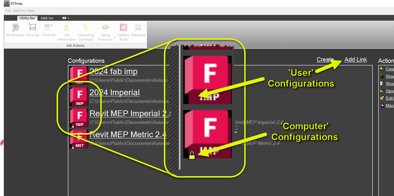
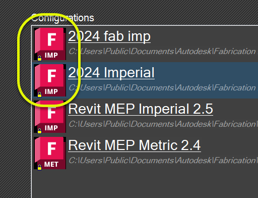
When you manually add a Fabrication Configuration to your system yourself, it only works for the currently logged in user. In fact, you may have noticed this with your own configurations compared to the default ones Autodesk adds during installation. You can see the difference by the presence of a little Yellow Lock icon in the lower left of the Configuration’s image.
So when you use the Add Link option to add a configuration, it’ll only exist for you. If someone else logs into the computer, the configuration won’t be displayed for the new user. Autodesk’s on the other hand…will still be there.
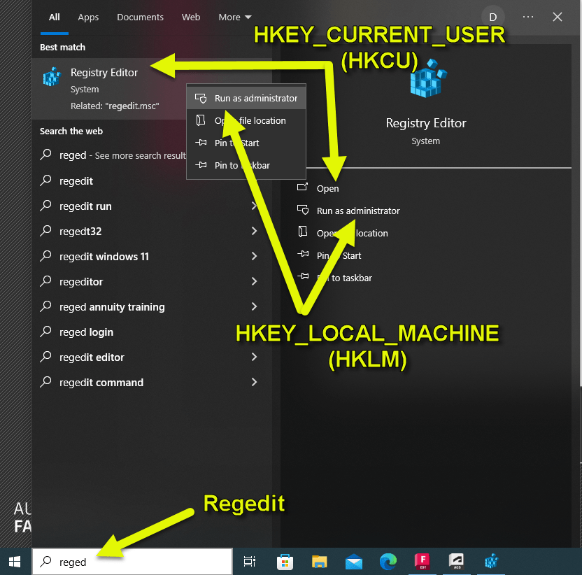
The difference between these two ways Configurations work is based on how the configurations are “configured” in the Windows Registry. So let’s take a look by starting the Registry Editor.
The first thing to know, is that there’s two ways to start the Registry. Just running the REGEDIT command opens the editor and displays everything. The other way is to Run as Administrator. When just run, you’ll have read/write access to the HKEY_CURRENT_USER branch (‘Hive’ is the proper term) often abbreviated as HKCU. This is the branch where the User configurations are stored.
The Computer based Configurations (like Autodesk’s) are stored in the HKEY_LOCAL_MACHINE branch often abbreviated as HKLM. When you run REGEDIT normally, you’ll see the HKLM branch but it’s Read-Only. To write to the HKLM branch, you’ll need to launch REGEDIT with the Run as Administrator option. Your IT Department may restrict this from you so you may need to involve them if you want to implement Computer based Fabrication Configurations.
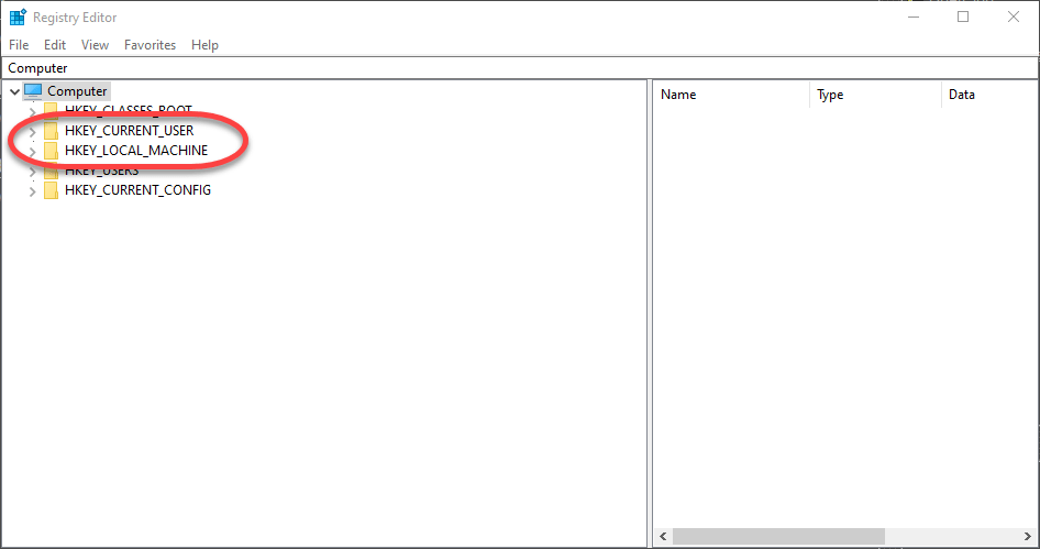
The other thing to note, is that when you Run as Administrator, the HKCU branch is there but the settings may be missing or different. This is because, the Registry Editor is technically running as another user and that branch is User specific. You can see the two branches I’ve referenced in the following image.
Converting Configurations to ‘Computer’ Based
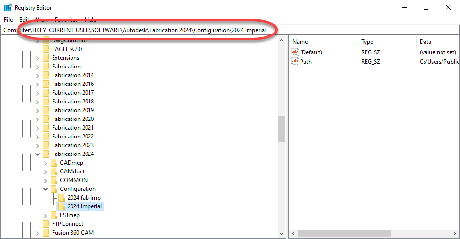
While you can edit the Registry manually, the easiest way to convert your Fabrication Configurations to be Computer based (not User) is to run the Registry Editor normally (not as Administrator) and export the HKEY_CURRENT_USER settings. The settings are in the key…
The <year> represents the version year of Autodesk Fabrication (CADmep, ESTmep, CAMduct, Remote Entry, etc.) or Revit. You can see that in the following image. If the Configuration key isn’t there, that means there’s no configurations “configured” for that version year. If a specific “year” isn’t listed, it means that version wasn’t installed.
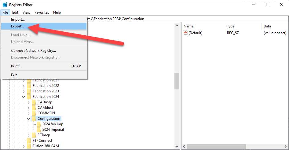
Once you get to the Configuration Key, you can export it using the File -> Export option as shown here…
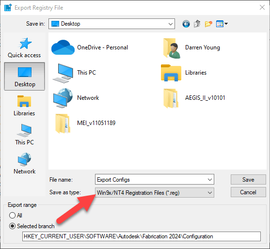
While you can Export a single configuration, I like to pick the Configuration Key and do them all. We can get rid of what we don’t want later. The main point to note when exporting is to change the Save as type: to the Win9x/NT4 Registration Files (*.reg) option. This will save the export in ASCII text which you can edit in Notepad.
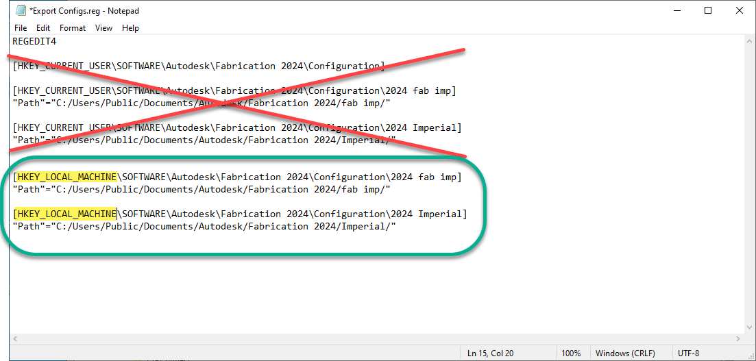
Once you export to a file, you can right click on the file and select Edit to open in Notepad. The following image shows how it looks and is marked up what I’ve removed vs added/edited. Note I also edited the Registry Hive from HKEY_CURRENT_USER to HKEY_LOCAL_MACHINE.
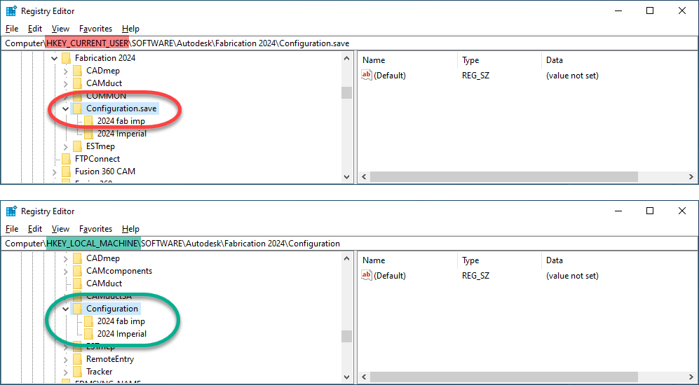
Once you’ve edited the file and saved it, you’re almost ready to import it. It’s generally not advisable to have the same configuration with the same name and same path in both the HKCU and HKLM branches.
So first, you can run REGEDIT normally and rename the Configuration folder…or just delete it (if you’re comfortable doing so). Then close the Registry Editor and run it again but Run as Administrator. You can now Import the file you just edited to import those new Registry settings. The following image shows what both branches might look like…
Now, when you launch Fabrication (CADmep, CAMduct, ESTmep, etc.) you’ll see the little Yellow Lock icon on your configurations. Revit won’t show that little icon but it does honor the ‘User’ vs ‘Computer’ configurations.
A Word About Fabrication ‘Profiles’
One side effect of ‘Computer’ or machine based Fabrication Configurations shows up if you use Profiles in your Fabrication Configuration. It doesn’t apply to Revit but does CADmep, CAMduct and ESTmep. When you use Profiles with ‘User’ based Configurations, the last active profile will be the default when you launch the program again. With ‘Computer’ or machine based profiles, you’ll always default back to the Global profile.
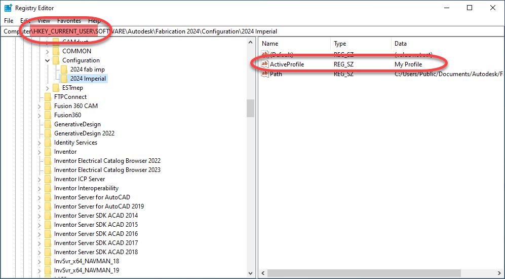
However this is easily fixed. To start, let’s look at the ‘User’ based configurations under HKCU when a profile was used…
You’ll see there’s now an ActiveProfile value in the configuration that wasn’t there before. That’s how Fabrication knows which profile to load by default. But also remember, the HKLM branch of the registry is normally Read-Only. So this means those programs can’t create this value when you change profiles.
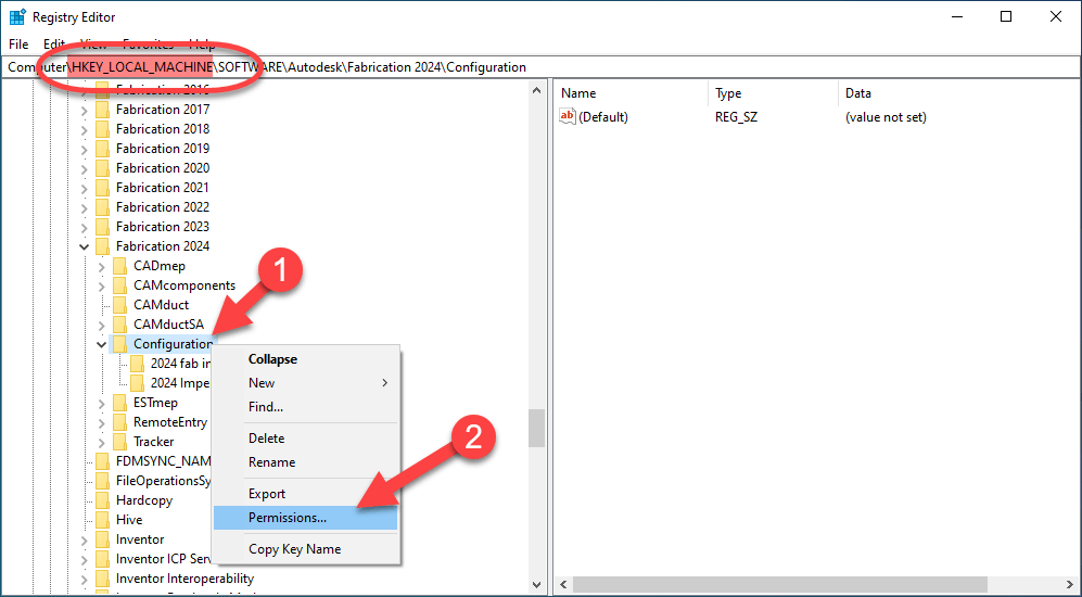
The solution to this, is making those registry keys Read-Write in the HKLM registry branch. You can do that by running REGEDIT as an administrator like before and navigating to the proper registry keys. From here, you can Right-Click on the Key’s name and select Permissions….
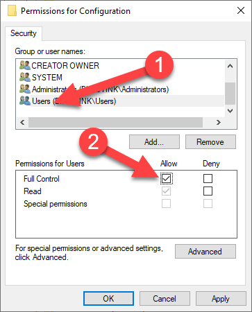
You can do this on a specific configuration or at the root Configuration key and the permissions will be inherited by the downstream keys. Once the Permissions dialog shows up, select the User permission group and select the Allow toggle for Full Control. Again, you may need your IT’s help if you don’t have permissions to do this.
This will now allow CADmep, CAMduct and ESTmep to save the last Fabrication Profile to the Registry in the HKLM branch so when you start the software the next time, it’ll be able to use the last Profile used.
One good side effect of changing these permissions…you’ll now also be able to import or create more Fabrication Configurations in HKLM in the future WITHOUT having to Run as Administrator as you’ll now have Read-Write permissions to those keys by default.
Make sure if you do these steps, to do them for all versions of Fabrication. You can even make entries for versions you don’t have installed so they work later if you install that version. So if you want to prepare for 2025 versions, you can copy/paste/edit those registry settings in the file you exported and rename them as 2025 (or older versions) all in the same file, Being proactive in this way will minimize future support downtime.
One of the more annoying things users find with upgrading Autodesk Fabrication is losing their customizations. Things like column configurations in the old version do not magically appear in the new version.
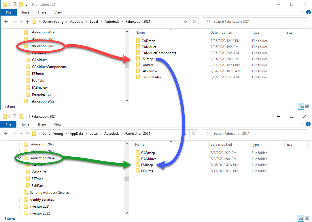
But this problem is actually fairly solvable. You just need to know where to look. And those settings are located in a local folder on your system. They’re USER specific….VERSION specific and PRODUCT specific. Here’s where you’re going to look…
Each user will have a folder for the version and product they’re using. If the Version/Product isn’t there, that means the product is not installed or that combination of Version and Product was not run yet.
So as an example, if you’re using ESTmep 2021 and have your columns all configured, you’ll find that folder. But if you just installed 2024 and not run it yet, ESTmep 2024’s folder may not be there. If it is, the settings will not be the same.
In our theoretical example of upgrading from ESTmep 2021 to ESTmep 2024, you’ll copy the folder/contents from 2021 into 2024. If the ESTmep folder doesn’t exist in 2024, just copy the entire folder.
You can even copy the contents of ESTmep to the CAMduct folder. This would make the column configurations the same for those two product to be the same. You can also copy a product version from one user to another user. Either on the same computer or a complete different computer.
The folders may have different numbers of file between them. They control different things. The lack of a particular file within the Product folder means a particular feature wasn’t customized.
You could play around using trial and error and see exactly which file controls which settings. But I’ve personally not found that to be worth the effort. I just copy them all so I know that my new install is the same as the prior.
Another thing I usually recommend to people upgrading, is find the person who’s settings you want to use. Save those folders somewhere on the network for easy access. When you install/upgrade other users, copy them from the network local to the person you’re setting up.
Using this technique, you can easily keep your Fabrication product customizations consistent…version to version, product to product, user to user and computer to computer.
Fabrication 2024 is out. I’ve updated all the reference information to include 2024 formats. As has been the trend the last few years, little has changed. Summary below…
I’m occasionally asked how one would add one of every size in a product list to their job. This very easy using ESTmep or CAMduct. CADmep however does not have this capability.
Here are the steps….
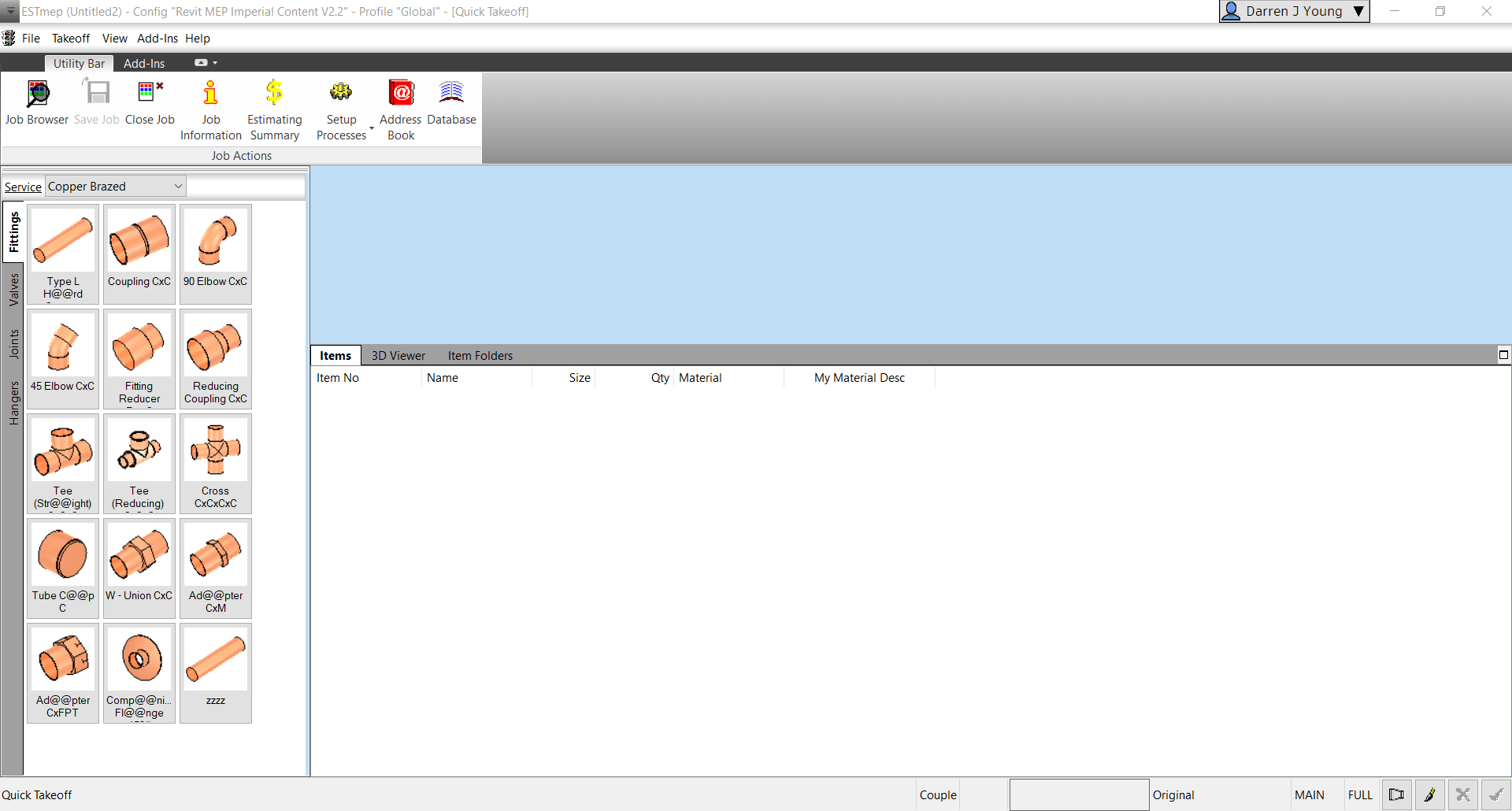
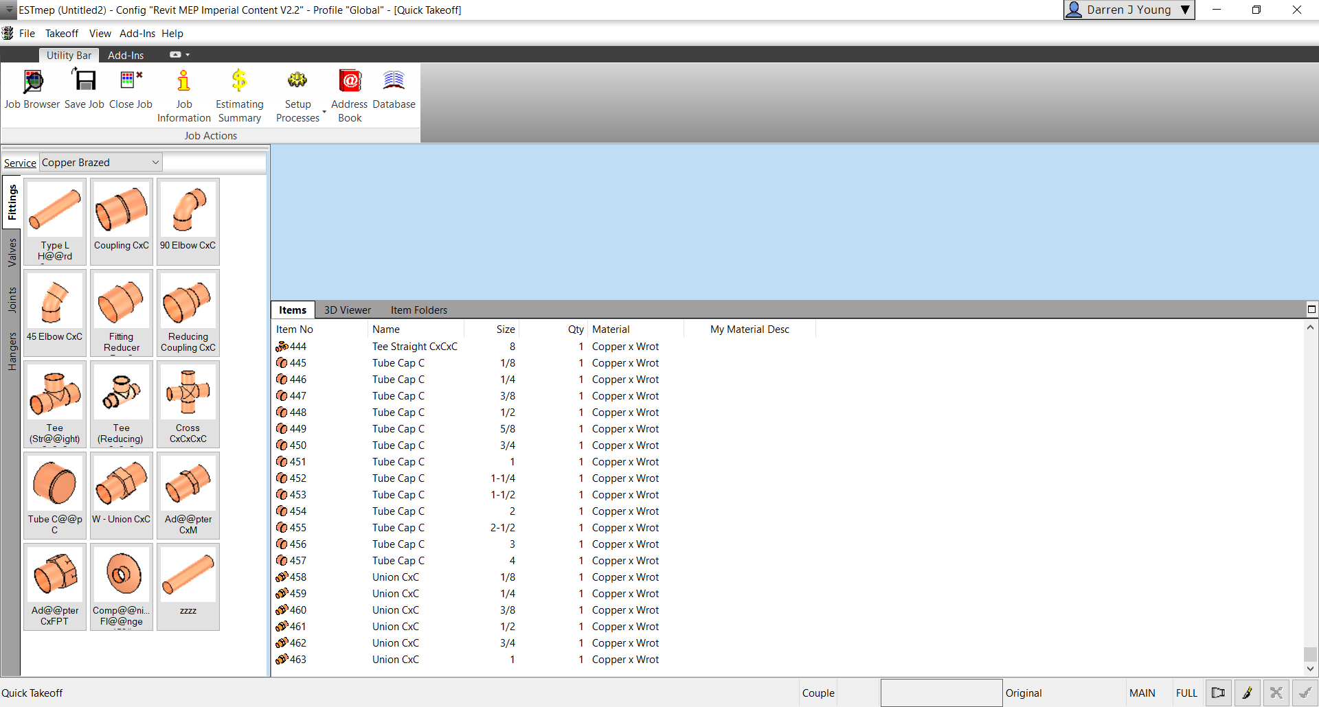
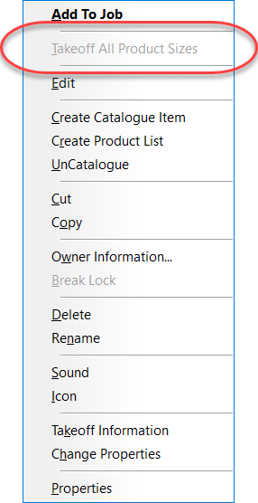
Step 1: Start ESTmep / CAMduct with a blank job.
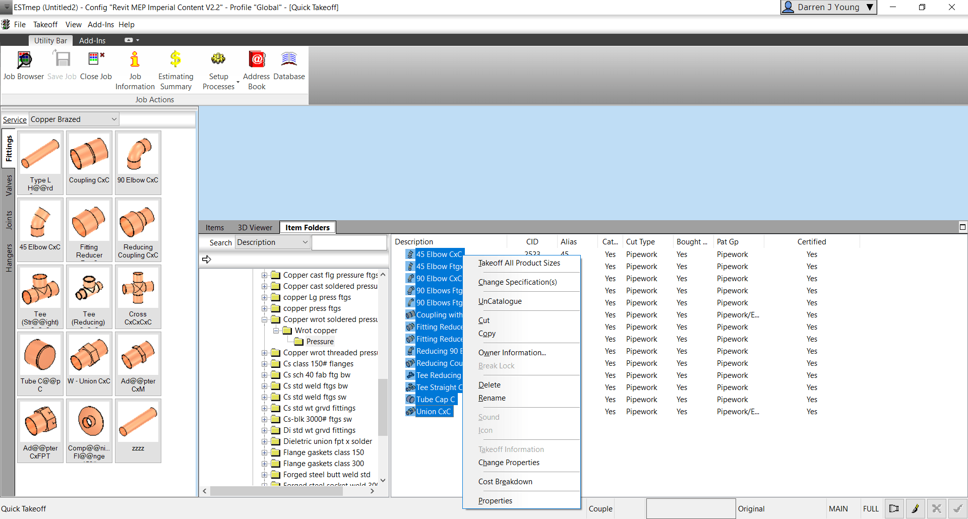
Step 2: Go to Item Folders and navigate to the folder with the ITM(s) you wish to takeoff all sizes for. Select all the ITM’s and press CTRL+SHIFT+Right-Click and select Takeoff All Product Sizes.
Step 3: Go back to the Items tab and review all the sizes of each item you selected.
Why Would You Do This?
There’s several reasons this may be helpful to you.
Any Size with dimensional errors is quickly found
A simple report shows you where you may have holes in your data (Price, Labor, Product Info, etc.)
Produce a quick MAJ that can be opened in CADmep (OpenJob) to measure each size to ensure dimensional accuracy.
If the option is grayed out/disabled, you’re one or more of the ITM’s in your selection is NOT Product Listed. For this to work, all items you’ve selected must be Product Listed.
I have a lot of people contact me and ask about software tools. They usually only know of some of them but not all of their options. Often they don’t fully understand what all they do or don’t do and how they may compare to each other.
So I figured I’d throw together a little summary of the better options that I’m aware of. There’s others out there but they’re really not penetrating the market or working toward integrating with other solutions near as I can tell. OR perhaps I’m just clueless and haven’t run across them yet.
I’ve listed the tools below in Alphabetical order to minimize suggestions of bias hopefully. But I tend to be pretty opinionated so take that for what it’s worth.
I’m sure everyone I’ve listed below will have issues with my descriptions to some degree and that’s ok. While I personally know many of people involved with these companies, I’m not an expert on their solutions. I highly recommend you talk to all of them and ask them your specific questions.
Note: I have not listed machine tool specific software like TigerStop‘s TigerTouch or Watt‘s new 3dPP Software. If you have tools like those, you likely already have those software options available to you and are familiar with them.
Other tools specific for Duct fabrication like Autodesk Fabrication CAMduct or Trimble ToolShop (Vulcan) are not covered because the Sheetmetal trades have been using them for years and are quite familiar with them.
The last thing to note is that just because a few solutions have an ‘X’ in the same column does NOT mean they even come close to addressing that category the same way or equally as well. Just that the tool helps with those major/broad categories I’ve listed. These tools do much more than I outline, I’m just covering some of my major observations. Review software demo’s and workflows closely.
Allied BIM is a great group of guys. They’re a little smaller than some of their competitors but don’t let that fool you. They integrate with more variety of machine tools than their larger competitors. So what do they do?
Fabrication Center – This is your production management system. Helps you keep track of what you’ve fabricated, what’s in process and what’s in the pipeline.
Fabrication Desktop – This is a machine control application that integrates with their other tools. It’s a huge upgrade to what you’d get out of the box from TigerStop or Razor Gauge.
Fabrication Tools – Help automate model and drawing production, spooling, etc. all in Revit. (you know, all those things Autodesk should have done but didn’t).
Allied BIM also sells machines last I knew. I’ve seen one of their setups and I tell you…if you want “White Glove” treatment and support….these are your guys. I don’t know anyone else installing a camera so they can remotely watch and assist your team on the shop floor. As they started out as a set of in house tools as a fabricator, they’re also the only company I know who’s run by guys who actually worked production. They’ve also recently partnered with ATG USA (Autodesk Reseller) to help support their sales efforts.
While a well known Autodesk reseller, they’re the new kid on the block competing against eVolve MEP. It’s hard to describe but while they’re competing against eVolve Mechanical, they’re approach to tools they’re building seems quite different. I’m pretty impressed with what they’re doing and where they’re going. General feel is instead of big complicated commands that you use once in a while and do a lot, theirs are more a suite of simpler more elegant tools that you’re going to use again and again putting money back in your pocket.
Here’s a few offerings under the “BIMrx” branding…
BIMrx Core – A lot of general Revit management tools.
BIMrx Fabrication – Modeling automation and efficiency. Focus here is on Fabrication ITM workflows.
BIMrx Fabrication DBS – Don’t have a Fabrication ITM database? Here’s one you can just buy vs build yourself.
BIMrx MEP – Modeling automation and efficiency. Focus here is on RFA/Family workflows.
Microdesk has other offerings too but they’re not focused exclusively on MEP so I’m not going to cover them. I do however encourage you to take a look.
Formerly known as WebDuct, they started out as a field ordering tool for Ductwork and other materials. Their Ductwork workflows have various integrations to CAMduct, ToolShop(Vulcan), PractiCAM, etc. But don’t let their Sheetmetal origins fool you. They’re a material logistics tool (pipe, consumables, tools, etc.) that integrates into a number of ERP systems used by MEP contractors like Viewpoint, Coins and others.
One of their more recent additions is an online duct builder which might be a good competitor to GTP’s FieldOrderZ. But because of their field logistics focus, they’re not really competing against Msuite, Stratus Connect2Fab or Allied BIM….yet. There are customers of those products that also using BuildCentrix.
One of the new players in the Fabrication Content space is ENGworks Global. They build a lot of content directly for manufacturers. If you download content from a manufacturer, there’s a good chance it may be theirs. In early 2023, they’ve announced their product Fab360. This is their offering of a full blown database for Autodesk Fabrication. I’ve not personally reviewed their offering due to an NDA with another firm operating in this space (not on this list). None the less, don’t dismiss this casually. There’s a couple very well respected Fabrication experts associated with this company in recent years so I would expect this to be a quality offering.
eVolve MEP is a company and suite of tools spun out of Applied Software. Applied Software ended up picking up Fabrication support after TSI’s demise when they acquired Enceptia (formerly DC CADD).
Their bread and butter (among other things) are tools to help model authoring, spooling, hanger placement, etc. Once again, this is a company that really shouldn’t exist except for Autodesk’s inability to listen to customers. They’ve built all the things you’d need and more to model with ITM content in Revit in contrast to Trimble’s RFA/Family based SysQue. On the ITM side, Microdesk is really the only major competitor with MSuite’s FabPro and Victaulic Tools taking a good sized bite of the apple too.
eVolve Electrical – Electrical based model authoring and automation. Not sure but I think this is RFA based.
eVolve Materials – This is a materials management and procurement system.
eVolve Mechanical – ITM based model authoring and automation for duct, pipe and plumbing.
eVolve Origin – This is eVolve’s custom prebuilt ITM Fabrication database.
GTP’s Stratus product is another one of the big competitors in the production managements space. Their differentiator IMO started as a focus on machine tool integration but as other’s have caught up, it’s become their ability to highly customize the system. This makes it a bit unwieldly to manage but if you master it, you can make it do a lot of things nobody ever envisioned and things their competitors can’t do. This flexibility also makes it a little easier to incrementally implement IMO as opposed to a larger more encompassing rollout common with other software implementations.
Here’s some of the products GTP offers…
FieldOrderZ – This is a newer offering designed to facilitate ordering materials and even field based sketching of fabrication. It does intigrate w/Stratus but can also be used standalone.
GTP Connect – This tool is designed to facilitate procurement from models.
Stratus – This is GTP’s production management system. Works with CADmep or Revit as well as both RFA and ITM content. While GTP doesn’t have Spooling solution inside Revit, you can Spool completely within Stratus.
Syclone – This is a tool used to import PCF file into Revit to generate a model. PCF is a format that can be exported from a number of applications to exchange piping component data.
Wireworks – This is GTP’s model authoring tool but it’s specific to Electrical only. content in Stratus. There is no equivalent for mechanical that I’m aware of.
HangerWorks Pro is a Revit Add-In to help with Hanger placement and modeling. It was originally written by GTP for Dewalt. It then disappeared for a while and it’s just recently resurfaced again but completely rewritten by the developers at MSuite from my understanding. I’ve not seen what the new rewrite looks like but do have a demo scheduled.
MEP Track is another new production management system on the market. But it’s not like any other. Developed with a smaller contractor in mind, its production management without breaking the bank. It uses exports from CAMduct and ESTmep and leverages the data to enhance your production management capabilities. But don’t let their smaller budget conscious focus fool you. MEP Track integrates with CAMduct and your duct fabrication process way more than any of the other 1″big players” in this space.
Manufacton was really one of the first ‘Production Management’ solutions available in the industry. I’ve been told their original founder was from Autodesk and a lot of their funding came from some Autodesk insiders. However, unlike their 2 primary competitors at the time (MSuite and Stratus) they really seemed to struggle to gain market share in MEP. When I had my demo, they weren’t even able to tell me who any of their MEP customers were…I ended up telling them who they were.
Ultimately they looked for a buyer and were acquired by Vizz Technologies. I’m not familiar with Vizz Technologies or where they’ve taken the product since. However, it still appears to me to focus more as a high level, generic (not MEP focused) production management tool. Executive management may really like it but it doesn’t appear focused as much on the end users in Detailing or the Shop like you see with Allied BIM, MSuite, Stratus. Still, it’s worth a look of you’re looking for a solution to help manage your shop.
MSuite is one of the big players when it comes to production management. If you’re looking for a solution and don’t look at them, you’re not doing your due diligence. They have a number of things they do but the big differentiator of MSuite in my opinion is their incredible focus on productivity. If managing the labor (productivity/scheduling) for your fabrication and install is your focus, there’s nobody that does it better IMO.
I hear a number of Union contractors dismiss Msuite claiming they’re not allowed to “track labor” but I find this a bullshit argument and excuse personally. There’s a number of union contractors using MSuite including some of my friends working at one of my competitors locally. I’m more than happy to put you in touch with a number of users if you think production tracking and scheduling is an issue.
Here’s a high level list of some of their tools…
BIMPRO – This is MSuite’s set of tools for Model authoring. Spooling automation, Hanger Layout and more.
FABPRO – This is MSuite’s production management system. Track everything your shop fabricates and have complete visibility to the labor effort it takes. Works with both RFA and ITM workflows.
FIELDPRO – This is MSuite’s tool for tracking in the field. What’s been received…what’s been installed.
While MSuite has it’s roots in MEP, you’ll also see they’re making more headway in the industrial space than their competitors (IMO) near as I can tell. If you also do industrial work….take a serious look.
In a further boot to their credibility and playform, on May 13, 2022 MSuite announced they were acquired by Stanley Black and Decker. I’m expecting to see development excelerate even more with Stanley backing this suite of tools.
PypeServer is a little more difficult to explain. Most are familiar with it is from it’s early days as the programming and control system for Watts pipe profiling machines. But it’s changed in recent years and you’re likely not as familiar with who they are today.
Watts has since moved to using their own software 3dPP for their new machines. 3dPP looks to me like an almost identical clone (a very strong nod to PypeServer IMO). But PypeServer now supports a lot more machines…
Pre-2020 Watts
HGG
Machitech
Vernon
TigerStop
RazorGauge
At it’s core, PypeServer is most similar to a CAM program but yet it’s still quite different. So lets try to explain…
How PypeServer is different than other CAM programs from my perspective is their approach to a variety of things. For starters, most CAM programs output a CNC file for programming a part. PypeServer uses a database which can be used to recall production run parts or even queried to run reports on past production.
They also are starting to heavily leverage the cloud to facilitate data transfers eliminating the need to manage lots of files to program parts. One added benefit to this is it makes this a LOT easier to install a machine safely in your corporate network without having to add it to your domain and deal with antivirus or firewall issues that can affect machine performance. Instead, give it a connection to the web and that’s all your IT needs to do.
Another key distinction is that most CAM programs at best import exports from other CAD systems. PypeServer goes out of their way to integrate with others. Their list of importers is impressive. Each custom tailored to the CAD system they’re designed for. The Stratus import as an example, works automatically without the need for any operator actions. This minimizes the work within PypeServer to program the parts.
Another example of this is the ever growing list of Addin’s for other CAD systems to export more streamline the workflow. For our industry, their Add-ins for AutoCAD and Revit will push data to the cloud where it’s easily imported into their products without the need for file management. Here’s a rundown of their core products…
PypeServer Connect – This is their Addin that exports parts from Revit, CADmep, Plant3d to PypeServer Lyte or PypeServer Enterprise.
PypeServer Enterprise – This is their original program that’s used for Pipe Profilers.
PypeServer Lyte – This is their newest addition used to drive linear cutting equipment like TigerStop and RazorGauge.
In the interest of disclosure, I am on PypeServer’s Board of Advisors. That means that for whatever reason, the listen to my ramblings about the industry. They’ve not in any way compensated me to write this and I’ve not submitted anything written here for their review. These are just my thoughts…consider them bias or not as you see fit.
This company’s focus is field ordering of Duct and other accessories, hardware & material from the Field to Shop. Their application elminates the need for paper orders, spreadsheets, emails, faxes and phone calls for a more error free experiance eliminating the wasted time of traditional procurement methods.
I’ve been a big critic of Trimble for a long time. They’re history of buying multiple solutions, allowing them to get obsolete and then buying new ones always bothered me. However….I’m seeing signs of a new Trimble. A Trimble that’s interesting in bridging their solutions together and providing more open access via API’s an integrations.
So imagine my surprise to see their new Connect2Fab product in Tampa this January at the MEP Innovation conference. This looks like it’s going to go head to head against GTP’s Stratus, Msuite and Allied BIM.
So it’s new and that likely means it’s not as mature as some of their competitors. But it looks good and is impressive for just getting out of the gate. Considering all the other things Trimble offers in the market, this should be considered a real threat to competitors and a viable option for contractors.
Trimble’s other main tool is SysQue, their Model Authoring offering. Unlike eVolve Mechanical that’s focused in ITM/Fabrication Part workflow, SysQue is based on Revit’s RFA content. SysQue comes with it’s own content making it an attractive offering to many who don’t have the time, skills or money to invest in making their own.
Once again, this is a tool that shouldn’t need to exist except for Autodesk’s gross neglecte of the MEP contractor industry. But if you want to do fabrication modeling in Revit efficiently, you’ll need something so it’s worth a serious look.
Let’s face it…Trimble’s had everything they’ve needed and more to compete directly against Autodesk for some time. But their offerings didn’t integrate well and that wasn’t ever really a big strategy within Trimble. But that seems to be changing….from Detailing w/SysQue, Content (RFA & ITM), Submittal Management, Estimating, Collaboration and even ERP….imagine if (when) all that’s connected.
If Trimble manages to pull this off well and repair some of trust they’ve lost with some customers in the past, they’ll be well positioned to knock Autodesk flat on their ass IMO. Autodesk rarely shows up with a booth to any event with actual trades people in attendance. On the other hand you always see Trimble with a well staffed booth. I suspect you’ll see where this is going and how much traction it’s getting within 2-5 years.
BuildingData – This is Trimble’s Fabrication ITM content library. Hands down, the largest collection of ITM on the planet.
Connect2Fab – Trimble’s new Production Management solution for managing your shop from models.
EC-CAD – This is Trimble’s AutoCAD MEP based modeling tool (Formerly East Coast CAD)
MEPContent – This is Trimble’s AutoCAD Block, IFC and RFA content library.
SysQue – Trimble’s Revit Addin for Model Authoring
Note: In the interest of disclosure, I’m not a user of SysQue and RFA content for MEP fabrication modeling. I use ITM content. That said, a lot of folks think I’m anti-SysQue. That’s not the case. I actually was involved in it’s early beta testing/development at a past employer. It’s a perfectly valid tool and is the right tool for many companies. The only thing I was ever against were some of the early marketing tactics like “Native Revit” and other bullshit sales tactics which for the most part have ceased now that Trimble acquired it.
Victaulic Tools is another interesting software offering. They’re not really a software company trying to capture the fabrication modeling market. Rather they built the tools in large part for their own BIM Services group and they sell them for a very modest cost to customers. Regardless of which tools people buy, they often also buy Victaulic tools due to it’s low cost and very helpful utilities.
Virtual Building Supply (VBS) provides ITM content for Autodesk Fabrication users. Whether you work in CADmep, ESTmep, CAMduct or Revit with Fabrication Parts, if you need ITM’s added to your database, VBS is a good source of high quality content. If they don’t have what you need, reach out and they’ll quote you to build it. Unlike many other content providers who provide “subscription” content services, VBS content is a “buy it once” model.
VBS also will provide a full database if you are in need as well. They’ll even manage your database. So if you need a full database or just a few ITMs, they’re well worth looking at.
Summary
So that’s my list of many of the major software tools available. There is no perfect solution. Many can be used alone or in conjunction with the others on the list. Some are even both competitors and partners with each other.
I really encourage everyone to look at all these tools if they address the issues they’re trying to solve. Just don’t get caught up on buzzwords. There’s a lot of users in the industry that will give you the pros and cons of each of these tools.
Do use use PDF Underlays in your ESTmep takeoff? Do the Pages come in all at once on separate tabs and layers? Or do you have to place them individually and make the tabs/layers yourself?
Maybe it worked one way for you and all of the sudden it seems to change to the other way for no reason. And despite looking, you can’t find a setting that changes this behavior.
What controls Auto Sheet Placement vs Individual is very easy to control, but it is hidden. Let’s take a look.
Individual vs. Automatic PDF Sheet Placement
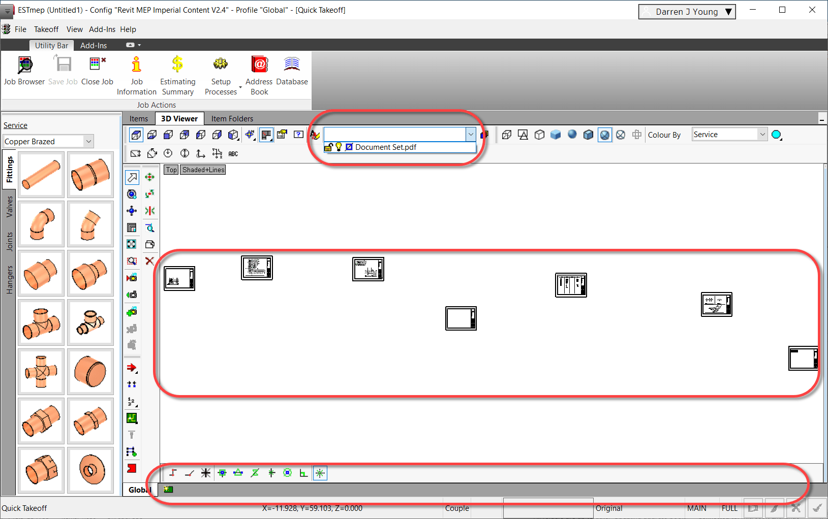
This images shows a 7 page PDF with each page imported as an Underlay separately. Notice they are not on separate tabs and they’re all on one layer.
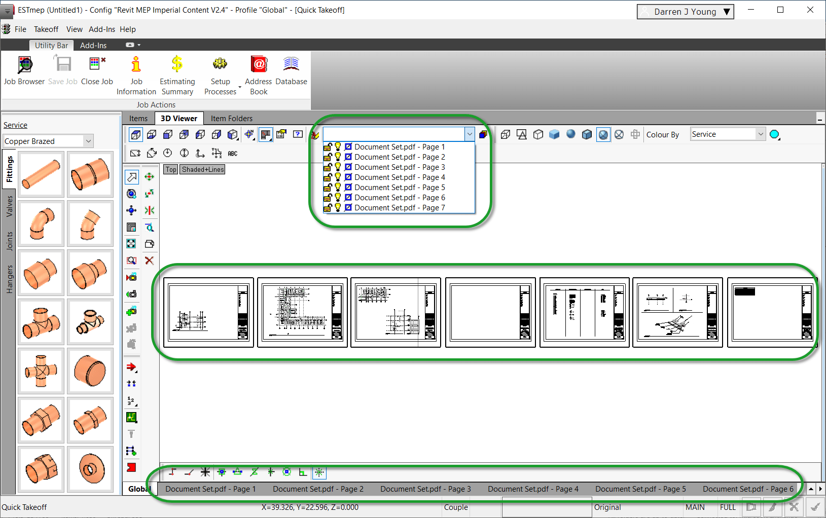
This next images shows what Automatic PDF placement looks like. Notice all sheets evenly placed in a row, each on a separate tab and layer.
So what’s the difference? What’s the magic setting? It all depends on how you select the “of type” dropdown when you select the PDF. This next image should explain it…
Let’s Look at Each Process
Place Sheets Individually One at a Time (of type = *.*)Place Sheets Automatically All at Once (of type = *.pdf)
ESTmep seems like it should be easy to calculate things like Area and Weight. A couple of the major factors in cost. But this couldn’t be further from the truth. It’s difficult to understand “Where” numbers are coming from. Here’s a few tips for troubleshooting.
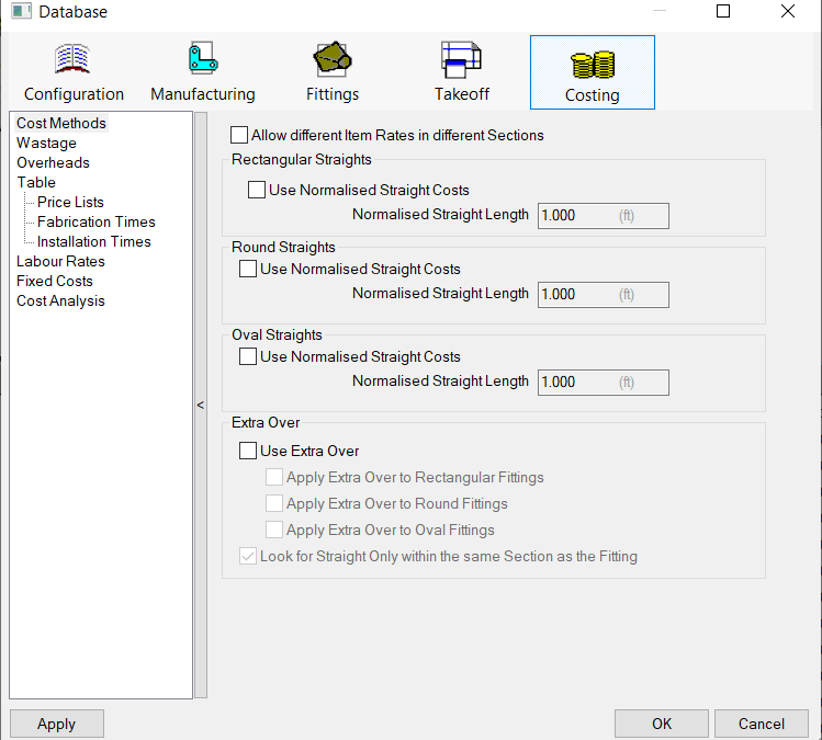
Eliminate Wastage and Costing Adjustments
Make sure Normalization is turned off for costing. You can do that here…
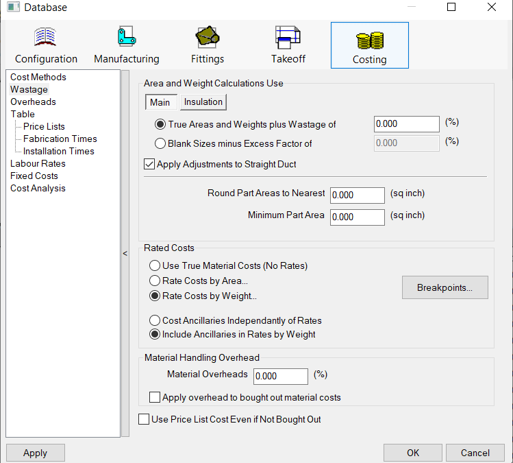
Next, eliminate any Wastage factors. Here’s what that might look like…
Create a Neutral Takeoff
There’s so many adjustments and factors that reporting properties it’s hard to tell what all makes up a number. The best way to find out what makes up a number is to make a Takeoff that eliminates as much of the factors as possible so you start with the core properties.
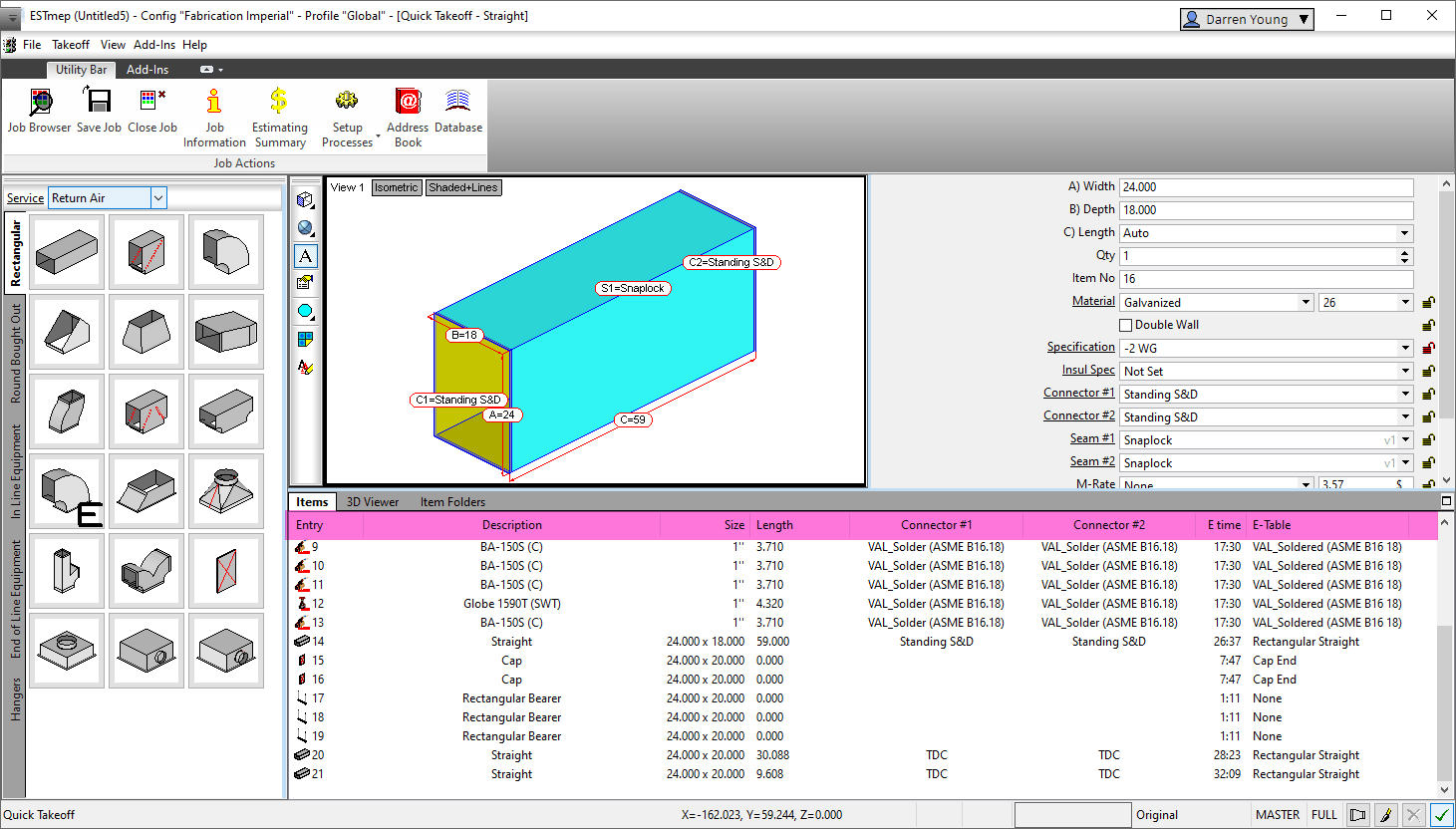
You can do this by adding Duct with simple numbers…12″ x 12″ x 12″. Duct with no connectors and no seams to eliminate allowances and sealant. Sizes that either don’t use stiffening or a purpose built specification that eliminates stiffening.
In my test, I created 20 pieces of Straight Rectangular Duct, You can do other fittings or Round/Oval too but start with the simplest and once you get dialed in and understood, you can expand to Round Straight or Fittings, etc.
Qty of 1
12″ Width x 12″ Depth
12″ Length
24″ Length
36″ Length
48″ Length
60″ Length
24″ Width x 24″ Depth
12″ Length
24″ Length
36″ Length
48″ Length
60″ Length
Qty of 2
12″ Width x 12″ Depth
12″ Length
24″ Length
36″ Length
48″ Length
60″ Length
24″ Width x 24″ Depth
12″ Length
24″ Length
36″ Length
48″ Length
60″ Length
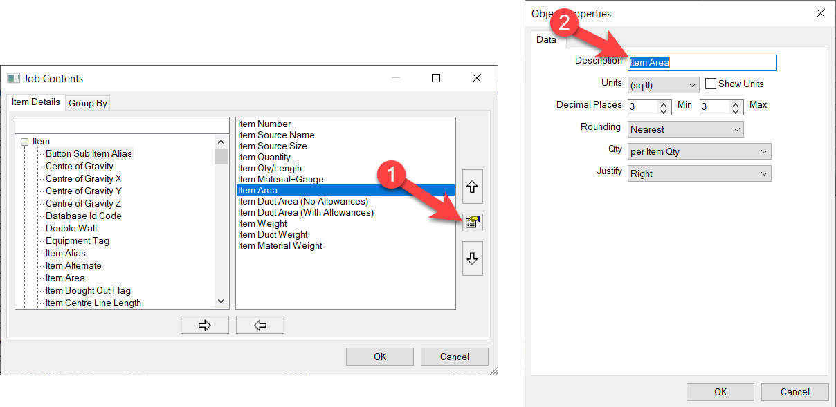
Customize Takeoff
Takeoff in ESTmep can sometimes list “Many” properties for Area and Weight or Quantity. When you add them, they typically just list “Area” or “Weight” making them unclear what they are. You can customize the takeoff Description to reflect which property it maps to. This way you can add them all and see the differences.
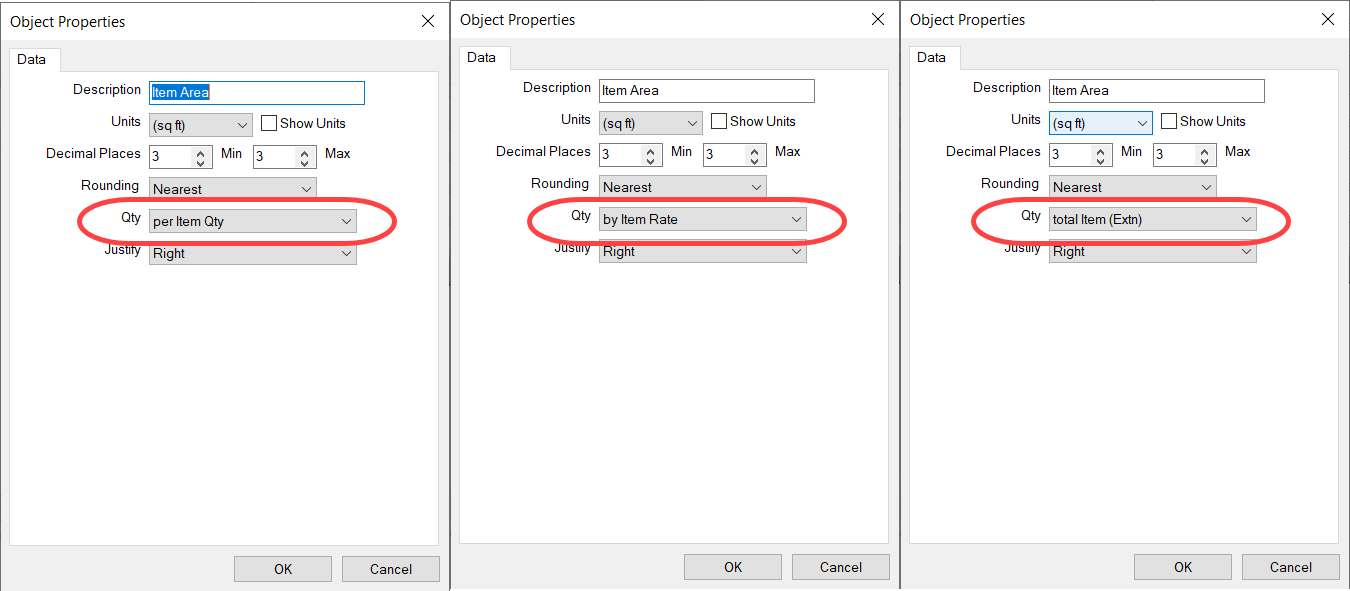
Test Various Quantity Units
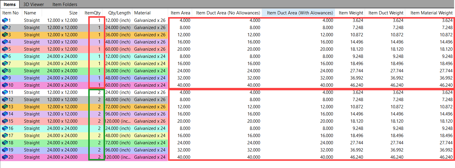
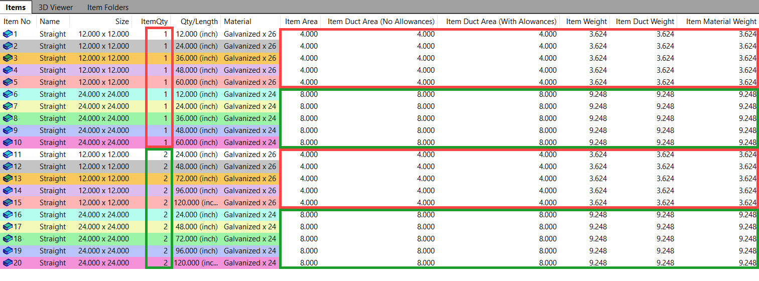
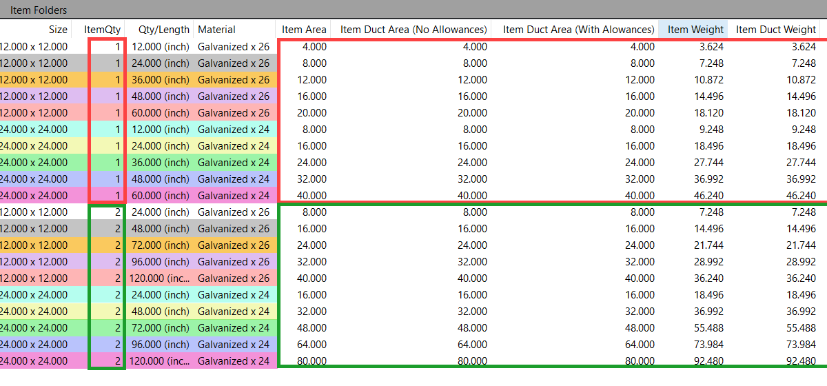
Each Property in Takeoff also has the ability to change the Qty Units. Here’s the 3 settings you have can reflect what Area and Weight is displayed. Here’s what those settings look like…
Here’s the results of those settings on my sample duct…
Per Item Quantity
Per Item Rate
Total Item (extn)
You can see “Per ITem Qty” gives you likely the closest to what you want. Exept it doesn’t take into account the Quantity of fittings. Quantity of 1 vs 2 is the same Area/Weight for the respective sizes.
“Per Item Rate” seems to be furthest from what you’d think. It’s really a ‘Per Ft’ value.
Lastly, the “Total Item (extn)” gives you most likely what you want and also taking into account the quanities of fittings.
Validate Data
Now that you have sample data and simple numbers, you can start doing the math. Look at the material and gauge and find the weight or area and see how your numbers respond.
Once you get comfortable that the numers are correct, start by adding in Seams or Connectors and see if the ancillary weights get added as you expect. Note that you’re numbers may be a little “off” based on Seam or Connector allowances and notching. Try adding only one thing at a time.
If you want to test how Wastage or Costing methods apply, you’ll want to go back to simple duct…No Seams…Connectors….Stiffeners, etc.
Keep things simple. Experiment. Check the numbers. Remove one of the factors and add another and try again. Then combine factor and verify your data is adding up properly.
Unfortunately there is no easy path or roadmap. But by starting with simple datasets and incrementally testing added features or factors, you can start to get a better picture of where your values are coming from.