What Does COST TYPE do on ITM Content?

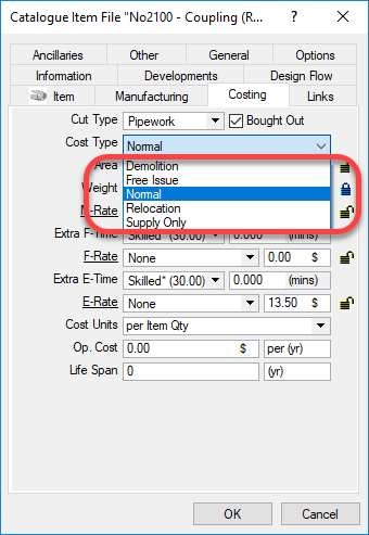
When you build Autodesk Fabrication content, you may have noticed one of the properties “Cost Type“. You can see this setting is shown in the following image. 

If you do some searching online, you may run across an explanation for some but not all. As Autodesk explains in it’s online help….

  • Normal – Reads the MaterialFabrication, and Installation tables to generate costs of all materials, fabrication labor and installation labor.
  • Supply Only – Reads the Material and Fabrication tables to generate the same costs of material and fabrication but NOT installation. (You’d typically use this if you are fabricating for others outside your company.)
  • Free Issue – Reads only the Install table when calculating costs.

This leaves two remaining values that can be set. These are not documented by Autodesk. These two serve the same purpose…

  • Demolition – Used as a filter for Labor table value sets
  • Relocation – Used as a filter for Labor table value sets

Using these values would allow you to build a labor table for relocation that would include uninstall and reinstall time. You could also use the demolition value to build a labor table for removal only of an item. 

While you would think these only would apply to an install table, these filter values are also available for the fabrication table. At the very least, this opens up the possibility of using it in creative ways to serve whatever purpose you like.

Defensive Driving for Coders

Disclaimer: I’m not a professional coder. Just a good hack, script kiddie, amateur, whatever you want to call me. But I’ve been doing it for a while and I tend to be good at finding ways to make things less error prone. I also pickup tricks from industry peers who humble me with their ability.

If you aren’t a professional programmer, you’ve likely never been told either. So I’m telling you as its helped me and I’m sure it’ll help you too if you’re an amateur like me. 

This works regardless of language. Whether you code in Visual Basic, AutoLISP, Java, C# or any other language the concepts are the same but the syntax will be different. For this reason, I’ll use pseudo code…that is, syntax that isn’t any particular language but uses terms obvious to describe what’s going on.

The Issue with Strings (Text)

A common activity in any programming is reading text, often called String data types. You read the value from somewhere else like a property or have the user type the data. You then need to test the data in a conditional statement to see if the data is valid. You may also be testing to see which action to take depending on what was typed. 

The problem when doing this is you don’t always know the case used when typing. Most conditional testing on string data is CaSe SeNsItIvE. Take the following examples….

MyValue = "Elephant"
if MyValue = "Elephant" then
MessageBox "Yes - There's an Elephant in the room"
end if

This code works because the case of the text strings is identical. But what about this….


MyValue = "elephant"
if MyValue = "Elephant" then
MessageBox "Yes - There's an Elephant in the room"
end if

In the above code, the test fails because the “E” in “Elephant” is now lower case.  This is very simple to solve and is obvious once it’s pointed out.

To resolve this, when you test a String value, use code to force the value to either UPPER (or lower) case and test against that. Now look at the following code…

MyValue = "Elephant"
if
Upper(MyValue) = "ELEPHANT" then
MessageBox "Yes - There's an Elephant in the room"
end if

  …or this example…. 

MyValue = "Elephant"
if
Lower(MyValue) = "elephant" then
MessageBox "Yes - There's an Elephant in the room"
end if

In either of these examples, we take the value we want to test, force it’s case one way or the other and test against that case. Now it doesn’t matter what case is typed by a user or returned when reading a value, the test is now essentially inoculated from case differences by forcing it one direction or the other. 

A Less Obvious (but related) Tip

Another common mistake I see people do is not use this technique when they know the software better. For example, lets say you wanted to retrieve the type of AutoCAD object and noticed that AutoCAD ALWAYS returns the name in mixed case….”Line”. 

It’s common for less experienced programmers but very smart and observant coders to ignore the tip I just suggested. I’d advise you to NOT do that…always use a forced case when testing text strings. Even when you’re sure the value you are reading and testing is always a particular way.

Why? What happens if…that pesky if…AutoCAD or whatever you are using changes? Autodesk sees a lot of programmers…maybe they overhaul AutoCAD code and object types are now returned upper or lower or a mix? You’ve now put in the hands of someone else if your program will break in the future. As unlikely as it seems, it’ll eventually happen. The key to writing resilient code is tricks like this. Think of it as a coder’s version of “Defensive Driving”. Anticipating future inconsistencies and planning for them makes your code more resilient and less likely to break on your next upgrade. 
Fabrication CADmep Help

It’s sometimes easy to miss new things. This is why I want to point out something that was added in 2015. CADmep now has an APPHELP command. You can type APPHELP at the command prompt to bring up CADmep’s help system.

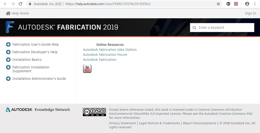
If you’re online, the help is pulled from Autodesk’s web site from the following URLs…

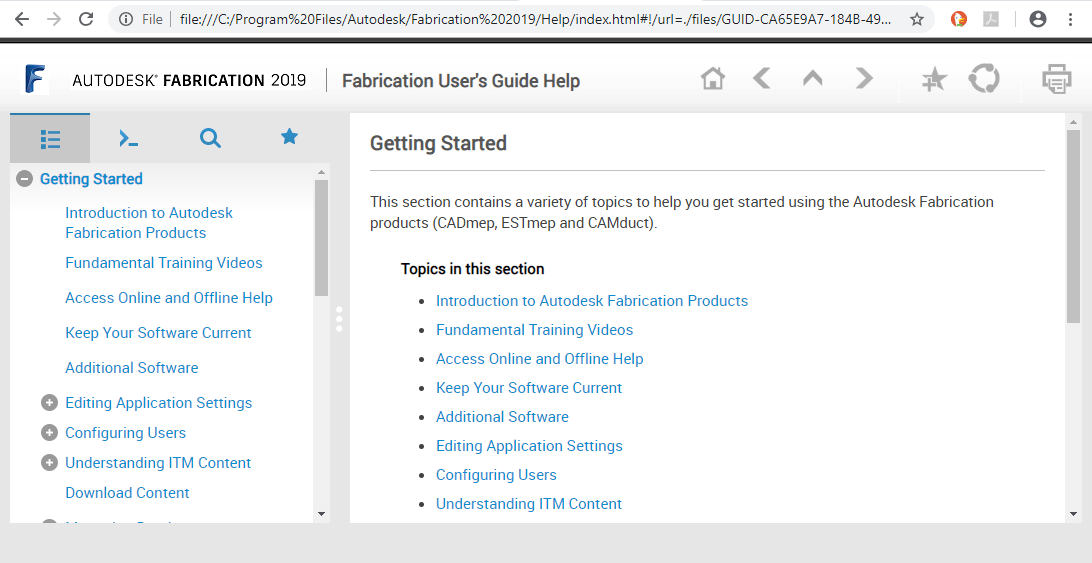
When you’re not online, APPHELP  loads the help system that’s installed locally. You can find it in these folders…

  • C:\Program Files\Autodesk\Fabrication 2015\Help\index.html
  • C:\Program Files\Autodesk\Fabrication 2016\Help\index.html
  • C:\Program Files\Autodesk\Fabrication 2017\Help\index.html
  • C:\Program Files\Autodesk\Fabrication 2018\Help\index.html
  • C:\Program Files\Autodesk\Fabrication 2019\Help\index.html

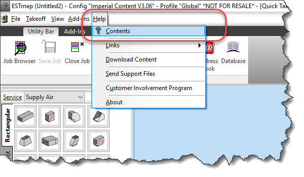
But what if you’re using CAMduct or ESTmep? No worries. The other products work the same way. Instead of typing APPHELP, type F1 on your keyboard or use the Help pull down menu.

TigerStop – Tip #1

More and more mechanical contractors are installing and using TigerStops. The company has been around for a long time in a number of industries but only recently have they started to get noticed by mechanical contractors. If you’re unfamiliar with them, you can find out more from their web site www.tigerstop.com. You may also want to view their Blog post about one mechanical contractor’s experience with them here.  I’ll be posting a few tips going forward as I get more familiar with them. To get you started, here’s my first Tip.

Install TigerTouch software on your computer

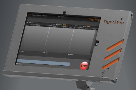
One of the options you can buy when getting a TigerStop, is the Tablet package that consists of a Windows Surface PC with the TigerTouch software. This package provides your TigerStop with a much friendlier interface that can be used to control your TigerStop controller.

While this software is used to control your machine, you can also install it on any computer. Simply download the Full installer from TigerStop’s web site and install. Installing on another computer has several benefits….

  • Test, and learn some of the software workflow in a safe more comfortable environment. This is a great way to train your shop staff how to use the interface without taking your machine out of production and without wasting any material.
  • Allow you to more easily get screen captures and produce documentation for your staff.
  • Test new software builds before updating your machine.

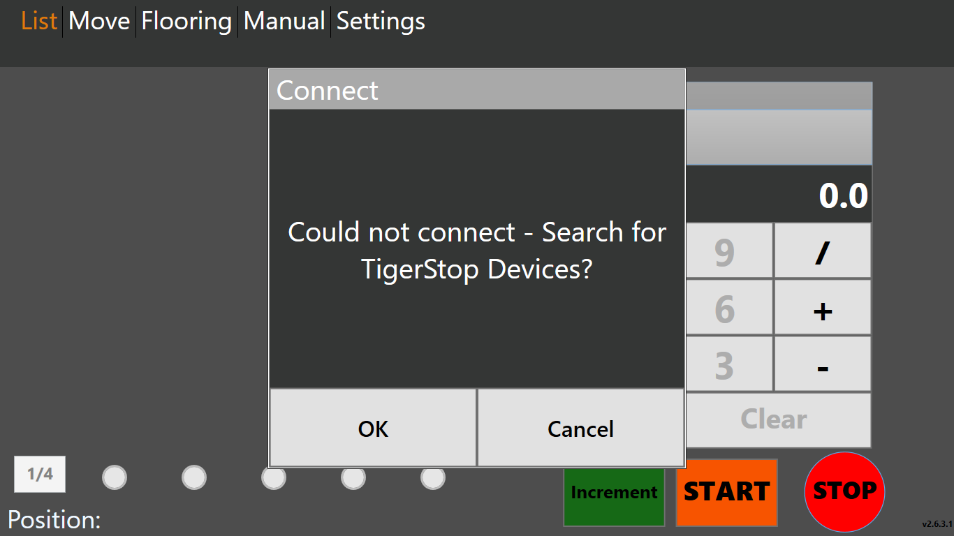
When the TigerTouch software starts, it notifies you that it can’t find a machine connected. That’s perfectly fine, just click cancel so it doesn’t try to look again.

From here, you can now use many of the functions of the software. When you click START, instead of the software waiting for your saw to operate, your cut lists are just processed automatically for for each stock size you enter. Here’s a video of the software opening a Cut List and processing it on my system which is NOT connected to an actual TigerStop machine.

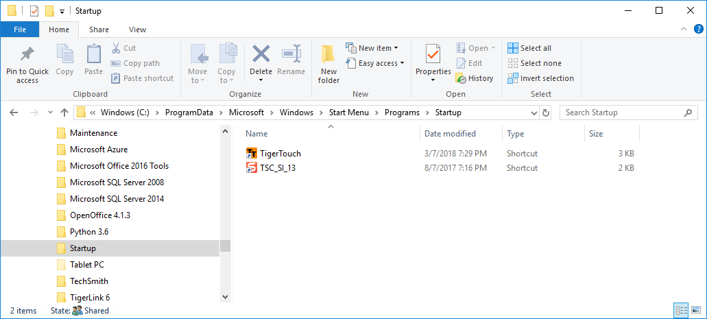
One last item…When TigerTouch installs, it assumes you’re installing a machine so it’s configured to automatically run when you log into Windows. To stop this, simply remove the TigerTouch Shortcut in the Windows Startup folder. The shortcut is located here:

C:\ProgramData\Microsoft\Windows\Start Menu\Programs\StartUp

When you’re browsing to this folder you may not see the ProgramData folder because it’s a Windows System folder which by default is configured to be hidden. Simply type in the folder name and you’ll be able to browse to that folder.

Programmer’s Trick: Custom Number Rounding

Most programming languages have a function to round a number to the closest whole number using standard math rules. Anything fraction of a number < 1/2 typically rounds down and any fraction of a number >= 1/2 rounds up. In Visual Basic, there’s a “Round” function, C# has a “Round” method and Excel even has a “Round” function.

  • 1.0 already a whole number, rounded value remains 1.0
  • 1.25 rounds DOWN to 1.0
  • 1.49 rounds DOWN to 1.0
  • 1.5 rounds UP to 2.0
  • 1.75 rounds UP to 2.0
  • 2.0 already a whole number, rounded value remains 2.0
  • …etc…

Some languages lisp AutoLISP, doesn’t have a function that behaves like this. Instead, AutoLISP had a “FIX” function that rounds down, regardless of the fractional component.

  • 1.0 already a whole number, rounded down remains 1.0
  • 1.25 rounded down becomes 1.0
  • 1.49 rounded down becomes 1.0
  • 1.5 rounded won becomes 1.0
  • 1.75 rounded down becomes 1.0
  • 2.0 already a whole number, rounded down remains 2.0
  • …etc…

If you use a language like AutoLISP that only drops the fractional component of a number (essentially always rounding down) to function like real math rules, this is easily accomplished by simply adding 0.5 to the number before rounding. This changes the resulting rounded number to the same as traditional mathematics would round the numbers.

  • 1.0 + 0.5 = 1.5 rounded down becomes 1.0
  • 1.25 + 0.5 = 1.75 rounded down becomes 1.0
  • 1.49 + 0.5 = 1.99 rounded down becomes 1.0
  • 1.5 + 0.5 = 2.0 rounded down becomes 2.0
  • 1.75 + 0.5 = 2.25 rounded down becomes 2.0
  • 2.0 + 0.5 = 2.5 rounded down becomes 2.0
  • …etc…

So far, this is quite simple. But what if you wanted to round to the nearest 1/8? Or 1/2?  Again, many of the rounding functions in programming languages have the ability to round to a certain number of decimal places by specifying the number of decimal places as an argument to the rounding function. This works great on decimal values where you want to round to the nearest 1/10 (0.1), or 1/100 (0.01). However, this doesn’t work in other fraction that are not base 10. Rounding to the nearest 1/8 yields 3 decimals (0.125) but 2/8 (1/4) yields 2 decimal places (0.25) and 4/8 (1/2) yields in 1 decimal place (0.5). So how is this done?

Quite simply actually. You can use another technique which shifts the decimal. This moves the fractional component you want to keep to the left of the decimal and leaves the remaining fractional components to the right of the decimal where you can round them off. It sounds more complicated than it is.  Let’s look at how this works by focusing on 1/8 (0.125).

What happens when we multiply 1/8 (0.125) by a factor of 8? We get 1.0 which when rounded, stays 1.0, we then divide by 8 again which shifts the decimal back to where it belongs and we end up with out original number as follows…

0.125 * 8 = 1.0  rounded stays 1.0 / 8 = 0.125 (1/8)

Now let’s try this when the number is slightly larger….

0.126 * 8 = 1.008 rounded becomes 1.0 / 8 = 0.125 (1/8)

The key is…if you want to round to the nearest 1/8, you “MULTIPLY by 8, ROUND, then DIVIDE by 8″.  You can also use the inverse formula “DIVIDE by 1/8, ROUND, then MULTIPLY by 1/8″. Either formula works.

The same technique works if you want to round to the nearest 2 (even) or 3 (3, 6, 9, etc.).

  • 0.25 / 2 = 0.125 becomes 0.0 * 2 = 0.0
  • 0.5 / 2 = 0.25 rounded becomes 0.0 * 2 = 0.0
  • 1.0 / 2 = 0.5 rounded becomes 1.0 * 2 = 2.0
  • 1.99 / 2 = 0.995 rounded becomes 1.0 * 2 = 2.0
  • 2.00 / 2 =  1.0 rounded becomes 1.0 * 2 = 2.0
  • 2.99 / 2 = 1.495 rounded becomes 1.0 * 2 = 2.0
  • 3.0 / 2 = 1.5 rounded becomes 2.0 * 2 = 4.0
  • 3.5 / 2 = 1.75 rounded becomes 2.0 * 2 = 4.0

Using these techniques, you can quickly convert numbers into the rounded format of your liking, regardless of the programming language you use.

AutoCAD Selection Modes

AutoCAD does a lot of things for you automatically. Unless you’re an old timer from back in the DOS days, you may not be familiar with all the options you can choose from when presented with the “Select Objects:” prompt in AutoCAD, In days of old, AutoCAD displayed all of the options on the command line when going into selection mode. There were less options back then and a lot of what happens automatically now, you had to type the options for,

Today, there’s a lot more options so AutoCAD no longer displays them unless you type an invalid entry. Even then not all the options are displayed. Many of the options now are default behavior making the options less critical in operating AutoCAD efficiently. None the less, they are often helpful. Here’s a chart of the options available. A description of each option follows. For more detailed information, you can refer to AutoCAD’s Online Help using the following link.

AliasOptionModal / Single Use
AAddModal
ALLEverythingSingle Use
AUAutoModal
CCrossingSingle Use
CPCrossing PolygonSingle Use
GGroupSingle Use
LLastSingle Use
MMultipleModal
OObjectModal
PPreviousSingle Use
RRemoveModal
SiSingleModal
SUSub-ObjectModal
UUndoSingle Use
WWindowSingle Use
WPWindow PolygonSingle Use

  • Add (A) – Default mode for selection in AutoCAD. As you repeatedly pick items, they are ADDED to the selection set you are building. Stays in effect until switching to REMOVE mode.
  • All (AL) – Single use option that selects ALL objects in your AutoCAD drawing even if not displayed outside the current drawing area. Object on layers that are OFF and/or LOCKED will still be selected. Objects on layers that are FROZEN will not be selected.
  • Auto (AU) – Default mode for selection in AutoCAD. It’s combination of two other AutoCAD selection modes combined. SINGLE if you pick on an object, it will be selected. If you don’t pick on an object, BOX selection mode will be a CROSSING if the second point is to the left of the first selected point or a WINDOW selection  if the second point is to the right.
  • Crossing (C) – Single use selection mode where you pick two points to form a rectangle. Anything completely within or crossing the rectangle, regardless of the order or direction the points are picked is selected.
  • Crossing Polygon (CP) – Single use selection mode where you picks a series of points to form a polygon. Any object completely within or crossing the polygon will be selected.
  • Group (G) – Single use selection mode that allows you to type the name of a group to add the objects in that group to your selection. When specifying the names of unnamed groups, you must include the asterisk (*) prefix in the automatically assigned anonymous name AutoCAD gives it.
  • Last (L) – Single use selection mode that allows you to select the most recently added object in the drawing that’s visible, in the current drawing space and who’s layer is not off or frozen.
  • Multiple (M) – Modal selection mode used to selects objects individually without highlighting them for performance when selecting complex objects. When finished selecting objects you don’t want to highlight, press Enter and you’ll be returned to the default AutoCAD selection mode and still in the select objects prompt.
  • Object (O) – Default selection mode in AutoCAD where you select objects. Use this option to exit the SUBOBJECT selection mode.
  • Previous (P) – Single use selection that selects everything that was in the previous selection set (assuming the previous selection set wasn’t erased).
  • Remove (R) – Modal selection mode that cancels the default ADD mode to remove objects from your selection set. Most useful when it’s faster to select everything (ALL) and remove what you don’t want selected than it is to select everything you do want selected.
  • Single (Si) – In addition to being a single use selection modem, you can only select one object and the select objects prompt is terminated. If you fail to select an object in SINGLE mode, you are switched to BOX mode.
  • SubObject (SO) –  Model selection that allows you to select edges, faces, etc of complex objects. When in SubObject mode, you can no longer select Objects without using the OBJECT option to return to that selection mode.
  • Undo (U) – Single selection mode that removes the most recently added object (or objects if they were selected as a group) from the selection you’re building. Can be used repeatedly to keep removing object(s) in the reverse order they were added.
  • Window (W) – Single use selection mode where you pick two points to form a rectangle. Anything completely within the rectangle, regardless of the order or direction the points are picked is selected. Unlike CROSSING, anything that crosses the window will not be selected.
  • Window Polygon (WP) – Single use selection mode where you picks a series of points to form a polygon. Any object completely within the polygon will be selected. Unlike CROSSING POLYGON, anything that crosses the polygon will not be selected.