Warning: This is Part 2 of a 4 part series on merging Autodesk Fabrication Databases. Autodesk Fabrication software is extremely powerful and flexible but that also makes it very fragile. Use the below guidance with caution. I highly recommend backing up your configuration before attempting anything I’ve recommended. It never hurts to have a firm grasp of how Autodesk Fabrication functions from an administrative perspective. Consider yourself warned!
Method 2: ITM’s as Proxy
Another method of transferring data from one database to another is by using ITM’s. Simpy take an existing ITM or make a new one and set some of it’s properties to those you want to transfer. After you’ve completed this, copy the ITM to your desired database.
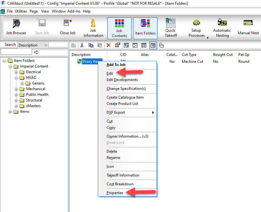
In your desired database, right-click on the newly copied ITM from the Folders view and select Edit or Properties as shown below.
Once the Edit Item or Item Properties dialogs are displayed, you can simply close them. The only purpose in calling them up was to force Fabrication to read all of their settings which in turn causes them to be created as Proxy entries in your database if they don’t already exist.
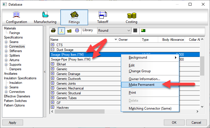
Once the database entries are in your new database, you’ll want to navigate to those database entries and make the proxy items permanent as shown below.
Pros: > Every property an ITM uses is supported. > Dependent database entries supported (e.g. Fixings on a Support) Cons: > Can bring in more properties than you want which need to be cleaned. > Time consuming for large property sets as multiple ITM’s required. > Proxy items must be manually made permanent afterward
Warning: This is Part 1 of a 4 part series on merging Autodesk Fabrication Databases. Autodesk Fabrication software is extremely powerful and flexible but that also makes it very fragile. Use the below guidance with caution. I highly recommend backing up your configuration before attempting anything I’ve recommended. It never hurts to have a firm grasp of how Autodesk Fabrication functions from an administrative perspective. Consider yourself warned!
Preface
You shouldn’t find yourself merging parts of different Fabrication databases very often. If you do, you may want to revisit your database management workflow and practices.
However there are a number of legitimate reasons you may do it. Most common is the database you’re using now isn’t the one you used a few years ago because you started over. It’s common for a Fabrication database to be a mess. They’re hard to learn and understand and while you learn, you do a little damage unknowingly. Maybe it’s turnover of the staff managing your configuration. Each new person will say they know how to manage Fabrication and what you’re doing is wrong. So they fix it. In the end, you end up with a mix of database management “Styles”.
And last but not least, it’s because trades men and women manage your data. Don’t get me wrong. Your trade staff are hands down the most qualified to manage an Autodesk Fabrication configuration. This is why the task gets assigned to them. But ultimately, what do companies “want” them to do? Detailing and modeling….run piping, plumbing, sheet metal, electrical, etc. Management more often than not pushes them to get back to modeling because management really doesn’t understand the importance of a good database. This leads to shortcuts and mismanagement through no fault of those doing the work. They’re doing the best they can given the constraints their under.
Whatever the reason, if you need to merge parts of different Fabrication Database configurations together, I’ll explain four different methods in the coming posts.
Method 1: Importing / Exporting Database Items
Export/Import Database is the most commonly used method. It’s also the most widely know. In 2014 and earlier versions, many of these were separate commands for each part of the database. In the 2015 version, they were wrapped up in a single command. This process allows you to export and import the following items…
Airturns
Insulation Specifications
Splitters
Ancillaries (except Kits)
Installation Times
Stiffeners
Connectors
Seams
Supplier Costs
Dampers
Sections
Supports
Fabrication Times
Specifications
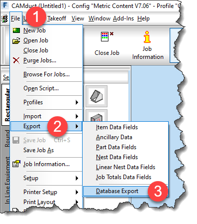
To initiate the Export process, type DBEXPORT at the command line in CADmep. In CAMduct or ESTmep, select File -> Export -> Database Export from the menu as shown below…
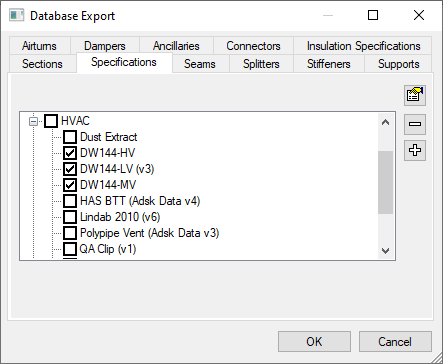
Once you start the command the Database Export dialog is displayed. You can switch tabs and select various database entries to export.
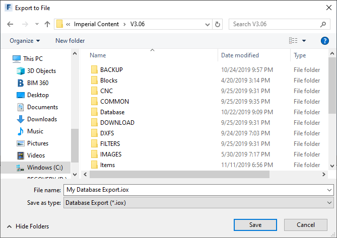
Once you’ve selected the items you wish to export, click OK and save the export file.
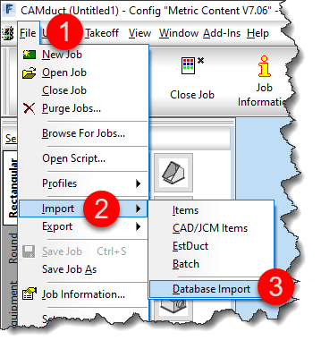
This *.IOX file contains everything you selected for export. You can then use this file to import those settings into another database configuration. The process for importing is very similar. Type DBIMPORT at the command line in CADmep or pick File -> Import -> Database Import in ESTmep or CAMduct from the menu shown below…
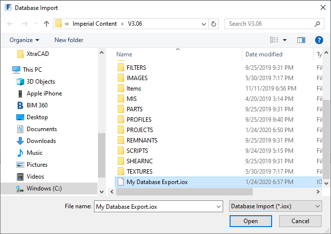
Upon initiating the command, you’re prompted to select an *.IOX file for import. Select the file you wish to import and click OK.
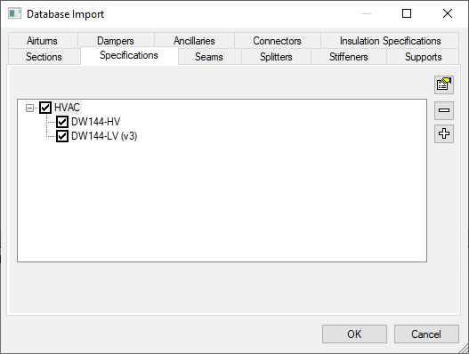
After selecting the file, you are presented with a dialog just like the Export dialog. In this one, you can navigate the various tabs and select what you would like to import.
There is no good way to see what’s available for import without checking all of the tabs. Only items included for export will be displayed. You can pick and choose to import some or all of the items that were in the export file.
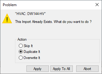
If an item you are importing already exists, you can choose to Skip, Duplicate or Overwrite the item. A word of caution, if your configuration has not been managed well, be very careful selecting the Apply to All button. There are times when the items Fabrication thinks are duplicate are indeed different items. This can be due to database corruption or misaligned indexes or any number of other reasons. If you’re concerned, select Apply for each item one at a time to verify the duplicates aren’t unexpected.
Pros: > Easy to use > Most common items supported > Dependent items (e.g. Ancillaries attached to a Support) are included even though they are not displayed. Cons: > Not all database areas supported (e.g. Materials, Ancillary Kits, Notches, etc.)
How many times have you had to reconfigure a system because a server changed? Remapped Drive letters? Links that used UNC paths? It’s downright annoying when IT needs to replace a server and it’s name is different. But it is understandable…systems get old and outdated and need upgrading or replacing.
What I don’t understand is why we use server names at all. Most Ethernet networks use IP addresses to route traffic, not server names. But nobody can ever remember all those numbers. When you type a server name, it pings the DNS server to locate the IP address of that server. Makes sense right.
But we don’t have to use server names…or IP addresses. DNS can be configured with a CNAME Alias (CNAME – Canonical Name). A CNAME Alias is just another human friendly piece of text that’s used to point to another Server Name, IP address or even another CNAME Alias.
What a CNAME Alias do for us?
To understand what a CNAME Alias can do for us, lets take the example of license server. All your client software points to the server name…let’s say is’s something like “P-LA-LIC01“. Now your IT rolls out a new server for licensing…it’s not going to be “P-LA-LIC02“. All your clients need to be updated to the new server name. Depending on the sophistication of your IT and the software they mightbe able to push an update. But more often than not, the local CAD/BIM Manager is left updating clients.
With a CNAME Alias, you could create a nice user friendly name like “ADSK-LICENSE“. All your software would use this name instead of the server name.
This CNAME Alias is setup on your DNS server. Most IT groups won’t give you access but if you know how it works, you can request and have them set it up for you. Just tell them you want a CNAME Alias named “ADSK-LICENSE” that points to “V-LA-LIC01” (ADSK-LICENSE -> V-LA-LIC01). Now when you’re ready to cut you users over to the new license server, have them update the DNS record for the alias to the new server overnight. The next morning, everybody is pointed to the new server, no reconfiguration required.
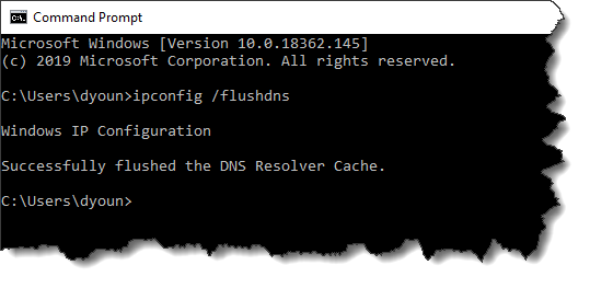
If someone has left on their computer, they may need to reboot to see the changes. In the unlikely event is still doesn’t work, they can open a DOS prompt and flush the DNS cache with the command line “IPCONFIG /FLUSHDNS“
Where does this work?
Just about where ever and ever where you would type a server name. You can make a drive letter using an Alias. You can use an Alias in a UNC path. We can even specify them to point to the IP address of network printer or other equipment.
The only real down side to using a CNAME Alias is that it doesn’t show up when browsing your network, But all things considered, that’s not a bad idea. If it were up to me, no user anywhere would ever know the names of the servers…only the Aliases. I really don’t know why this trick isn’t used more often. IT uses it for their own purposes, it just rarely gets implemented to affect the users. Using this approach, I’ve migrated hundreds of users in multiple locations to new servers with a 3 second DNS update in the evening. I suggest you give it a try.
We’ve all been there. Moving our mouse around trying to find the pointer on the screen. This can be especially troublesome in a shop floor environment. Computer screens are small. Full of dust and dirt. Poor lighting and perhaps even a poor mouse surface. All of these factors can make use of a computer on as shop environment annoyingly painful.
Beyond the obvious improvements like a larger, regularly cleaned monitor and improved lighting, there’s a couple simple tweaks you can make to keep your staff providing value as opposed to looking for a mouse pointer.
Advanced Mouse Options
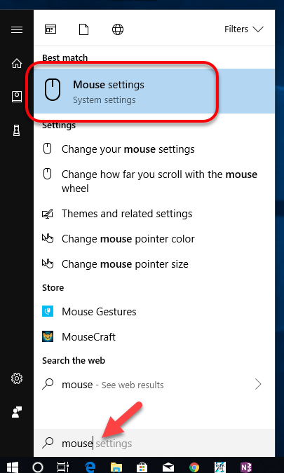
Using your Additional Mouse Settings, you can make a couple quick changes that will significantly improve the usability of a shop floor system. Simply press the Windows key on your keyboard and type Mouse.
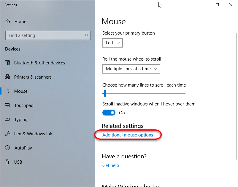
This should display the Mouse Settings option in the search results, that’s what you’ll want to click. This will bring up the Mouse Settings window. Here you’ll want to click the Additional Mouse Options link.
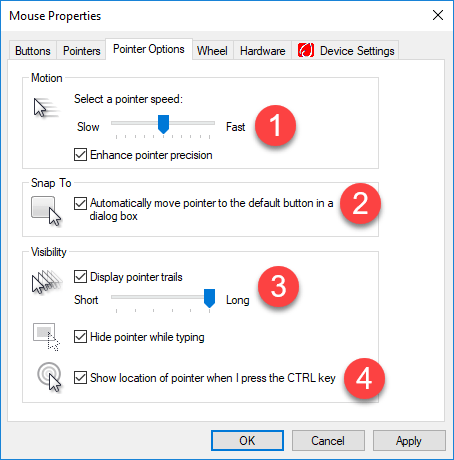
Now from the Mouse Properties dialog, there’s a few things, you should make adjustments to.
Select a pointer speed – You may want to turn down your pointer speed. It can be hard to find and track a mouse if it’s moving really fast.
Automatically move pointer to the default button in a dialog box – This setting may help depending on the software used on the shop floor. It may also be annoying. However, every time a dialog or window is opened, you’re cursor will be in a predictable location.
Display pointer trails – This leaves a few images of your cursor trailing around as you move your mouse. The longer the trail, the easier it will be to spot your mouse as you move it. Longer trails will have the most visibility.
Show location of pointer when I press CTRL key – You’ve likely seen this trick in software presentations. Press and release the CTRL key and a series of circles will radiate out from your mouse position.
A Word About Machine Controls
A lot of machines now are using Windows based controls. If these systems rely on the use of a Mouse instead of a touch screen, you may want to make these same changes. However these systems can often launch upon startup and make it appear you have no access to the Standard Windows interface. You can often simply plug in a keyboard and mouse into a USB port for quick access. You can then use standard Keyboard tricks to get you to a more familiar interface.
Press the Windows key on the keyboard to bring up the standard Windows menu.
Press Alt-Tabto gain access to other running or hidden applications.
If the control is running in Kiosk mode, you may not have access to the standard Windows options. In this case, press CTRL-ALT-DELETE to bring up the Task Manager. From the Task Manager, you can launch a new process or run a new program. You can simply type Explorer.exe and this will reload the Windows interface you’re use to allowing you to make the mouse changes.
When you host a BIM360 Design project, adding members to the project is a common task. If you haven’t done this before, you may notice after typing the address thatBIM360 Design doesn’t seem to recognize it.
When you watch the video, you can notice the blue “Select” button grayed out after typing the Email address. You can type a ‘comma’ (,) after the address to make BIM360 recognize it. You’ll see the Email address converts to a boxed control when you type a properly formatted address.
When you type a comma, this tells BIM360 Design that you’re done typing the address. You can also use a comma to separate multiple addresses. This is why the comma works even when typing a single address.
For years, I’ve shared my Fabrication COD scripts with the industry. These can be used to examine database content using Excel.
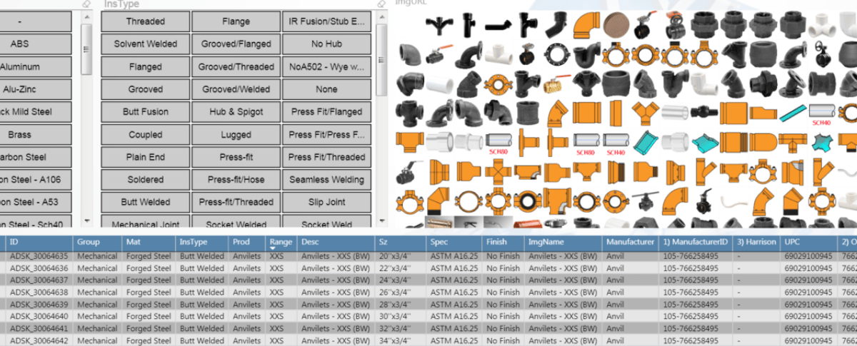
Tyler Phillips of Bruner Corporation recently posted a nice article on LinkedIn about using Microsoft PowerBI. His PowerBI dashboard provides a great way to help visualize the data behind your Autodesk Fabrication content.
Simply put, the scripts I share dump property data to multiple CSV files. Tyler used that data for some of the PowerBI data sources. This allowed him to built a dashboard which helps him visualize and navigate the data in a more meaningful way. And better yet, he publish a fantastic article on LinkedIn that explains how to do it.
Microsoft PowerBI Dashboard of Autodesk Fabrication Content
This is a great example of leveraging data from multiple sources. PowerBI help you mash it together to give you meaningful information that’s simple to understand and navigate.
If you’ve ever struggled with ESTmep reporting, just think of the possibilities. By taking the above concept and using it across CSV exports from ESTmep you could easily overcome gaps in estimating reporting.
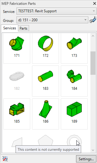
It no secret that not every Autodesk Fabrication pattern is supported in Revit. I’ve recently finished a more in-depth analysis of which patterns are and are not supported in Revit. Each of the 703 different pattern types were tested in each version and each update of Revit.
On the Fabrication COD Scripts page, you can find a Revit Support Report script. That script will analyse your ITM library and generate a CSV report of the status of every ITM in your Fabrication Configuration.
You can also find the complete results of my testing on the Revit Support page. Here’s a summary of the the testing…
Tested Version
Each of the below versions of Revit were tested with all the the 704 different patterns:
2016
2016R2
2061R2SP7
2017.0
2017.1
2017.2
2018.0
2018.1
2018.2
2018.3
2019.0
2019.1
2019.2
Testing Criteria
“Supported” for purposes of this testing is based on whether Revit allows a particular pattern to be used in the Fabrication Part Browser.
Testing Results
Testing results will have one of the following status descriptions.
No – No Revit support
Varies ({verison}) – Revit support varies between Revit version
Yes (Risk) – Revit does support but use NOT recommended due to issues
New ({version}) – New Pattern supported in later Revit versions
Yes – Pattern is supported in all Revit versions with no significant issues
Support Status = No
No – Parts not supported by the Parts Browser are obviously listed as having “No” support. There are a total of 84 different patterns listed in this category. They are as follows…
125
126
127
128
129
130
141
158
202
203
204
205
206
207
208
209
210
211
212
213
215
216
218
220
221
228
230
301
302
308
503
505
521
530
764
765
803
804
805
806
833
873
910
913
928
960
961
964
966
969
974
980
983
985
994
996
999
1049
1102
1106
1114
1142
1150
1152
1157
1161
1162
1165
1168
1169
1181
1194
1196
1198
2185
2189
2190
2191
2192
2199
2200
2873
3108
3873
Support Status = Varies
Varies(version) – In some cases, Fabrication Parts were initially allowed or supported in earlier versions and later were restricted. These parts have a status of “Varies” followed by the version where the change occurred. It’s recommended you avoid use of these patterns even in versions where they work as they will not be supported in later versions. There are 17 patterns that once worked in Revit but are no longer supported. They are as follows…
0
182
222
381
845
853
855
864
876
898
903
912
915
971
1105
1170
1175
Support Status = Yes (Risk)
Yes (Risk) – Patterns that list “Yes (Risk)” are technically supported in Revit but I highly recommend avoiding their use. Patterns with this status have issues like inserting at the Revit’s Project Base Point and not the cursor location. They also have a tendency to crash Revit if you attempt to grip or edit them. As a result, I highly recommend avoiding their use. There are 29 patterns in this category. They are listed here…
119
189
317
346
347
348
349
350
351
352
353
368
369
390
392
397
398
415
810
828
922
930
962
963
968
973
1159
1160
1176
Support Status = New
New (version) – Some patterns were not around in earlier versions of Revit but later added and supported in Revit. These patterns are listed as “New” followed by the version of Revit they became available in. These patterns are generally safe to use for Revit. There are 19 patterns in this category which are listed here…
217
1206
1207
1238
1239
1240
1241
1242
1243
1244
1245
1246
1247
1248
1249
1250
2197
2198
2217
Support Status = Yes
Yes – Parts allowed by the browser that work across all versions of Revit are listed with e “Yes” status. There are 555 patterns in this category. They are listed here…
Here’s another simple Attacher tip for Fabrication products. If you hold down the Shift key while clicking on the Attacher arrow in CADmep, ESTmep or CAMduct,. the arrow rotates the opposite direction.
Clickingthe Attacher – Notice it Rotates in the “Clockwise” Direction Clickingthe Attacher – Notice it Rotates in the “Counter-Clockwise” Direction
Sometimes the best tips are the simplest. They can often be forgotten about or never learned because of that. Here’s a reminder for those that may not know or have forgotten…
In CADmep, or the 3d viewer of ESTmep or CAMduct, you can hold the Control key while clicking the attacher arrow to rotate the arrow 180 degrees. The below screen recordings are both done from CAMduct but ESTmep or CADmep work just the same.
Clickingthe Attacher – Notice it Rotates in 90-Degree IncrementsCtrl-Clicking the Attacher – Notice it Rotates in 180-Degree Increments
When you build content, it’s often desirable to have certain dimensions or options locked. This even applies to connectors, seams and dampers but to a lesser degree.
If you have a lot of Dimensions and/or Options to Lock or Unlock, you don’t have to individually pick each one. You can lock or unlock many very quickly provided they’re in a row.
The trick is simple….pick the button to lock/unlock the first field you want to change, and then while still holding the pick button drag your mouse up or down. This is a fast an efficient way to lock large groups of properties without picking each one.
The following recording shows this process. We’re using Pattern Number (CID) 910 as our example.