Fabrication Pricing, Labor and Product Information
I have a lot of people ask how Pricing, Labor and Product Information (ProdInfo) works in Autodesk Fabrication. It’s a simple concept once you understand it. But it’s also rarely illustrated graphically so I’ll attempt a more graphical explanation here.
At it’s core Product Information requires the use of an ID, sometimes referred to as a Database ID. Pricing and Labor can be handled two separate ways depending how you need to price and labor your items. One of those ways is using Product Listed Pricing and/or Labor. When using Product Listed Prices or Labor, you also use an ID.
Generally speaking, 100% of your parts should have and ID. ID’s should also be unique without a very good reason for duplication. There are a couple good reasons to duplicate ID’s across content but we won’t get into that here. If this article is helpful to you, those reasons would only serve to complicate the issue at this point.
Product Information & Product Listed Prices & Labor
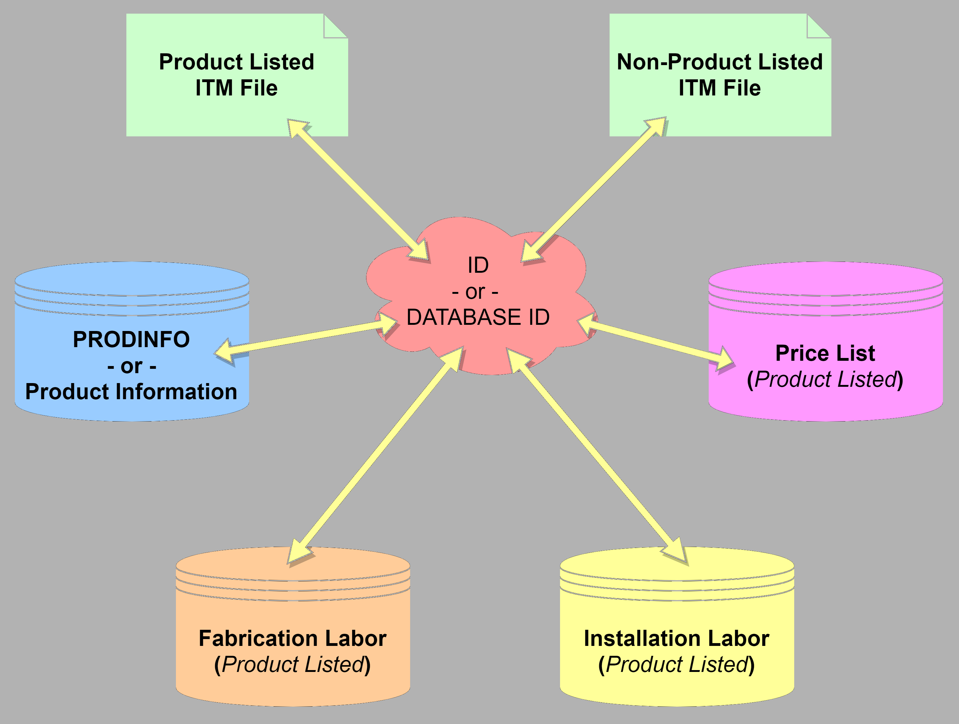
When you have an ID associated with your ITM content, that ID serves as the “Glue” to tie together all the other database tables in Autodesk Fabrication. An ITM with an ID, looks up that ID in the Product Information database to find the related product information. IT also does the same for Pricing, Fabrication Labor and Installation Labor.
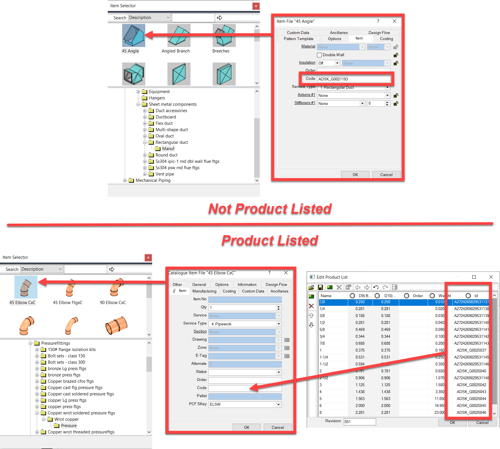
The following images shows where the ID is stored in your ITM Content. For ITM’s which are NOT Product Listed, you simply type the ID into the “Code” field from the Properties window.
For Product Listed ITM’s, it’s handled slightly different. You add the ID column to the Product List and add the ID’s there. When you add a product listed ITM to your model or takeoff, the value of the ID for the size you select gets automatically placed in the “Code” property. When that ITM is merely sitting in your library on disk, the value here doesn’t matter. It can be blank or any one of the ones in the Product List. Adding the ITM to your model then updates it to the proper ID.
Product Information
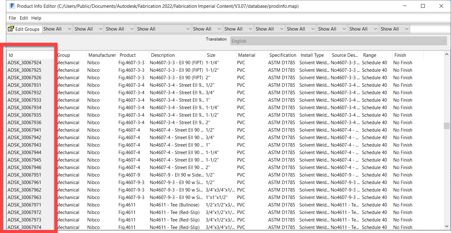
Product Information or ProdInfo for short lists additional data about the fitting or item. The following image shows the related data in ProdInfo with the ID column outlined.
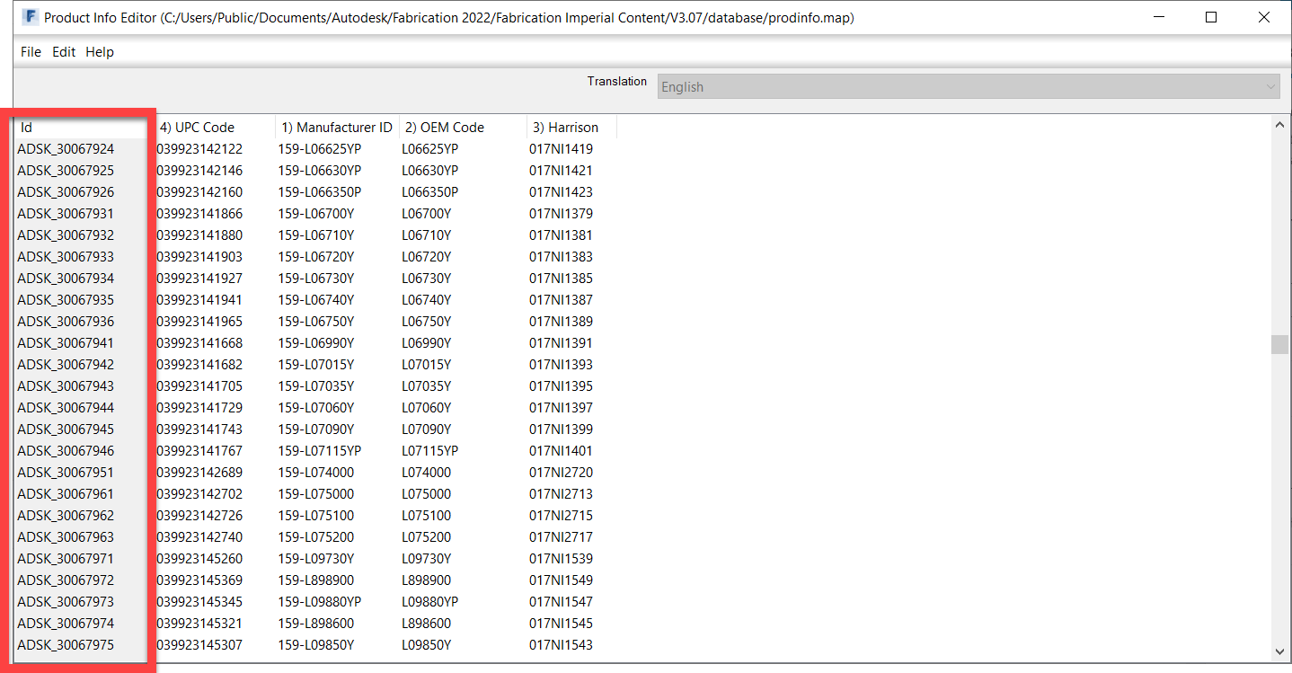
In addition to standard product information, you can also change to a Supplier view of ProdInfo where you can add additional columns for any other types of data or numbers you want to track. The following image shows some added data fields like UPC Code and Harrison HPH codes.
Pricing
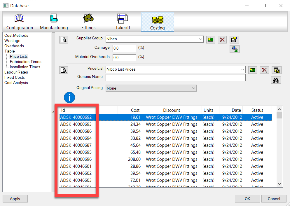
The following image shows a Product Listed Pricing Table. The ID is outlined. Here’s where you can add pricing information to the ID of the ITM. Note, the term Product Listed Price here is a little confusing because “Product Listed” prices can apply to non-product listed ITM’s. While an ITM may not contain a “Product List“, the pricing table is still a “List of Products” that are referenced by ID.
Labor (Fabrication & Installation)
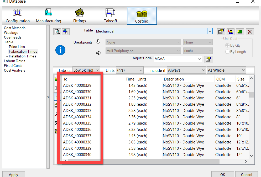
In the same way Price List’s work, Fabrication and Installation Labor work in a similar way. Product Listed labor can apply to any ITM, Product Listed or not as long as it has an ID. The following image shows Fabrication labor but Installation Labor works identically.
Breakpoint Pricing & Labor
A second way to specify Price and Labor doesn’t require ID’s because they’re not looked up from a list. These would be Breakpoint Price and Labor tables. With this type of Price or Labor table, you build a 1d or 2d Breakpoint Table that uses the part’s size as a guide to look up the proper price or labor rate in a matrix.
Price Breakpoint
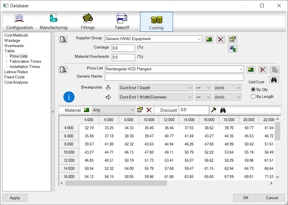
The following image shows a Pricing Breakpoint table. You can make more than one breakpoint grid and have each apply to a different material if you have the need.
Labor (Fabrication & Installation) Breakpoint
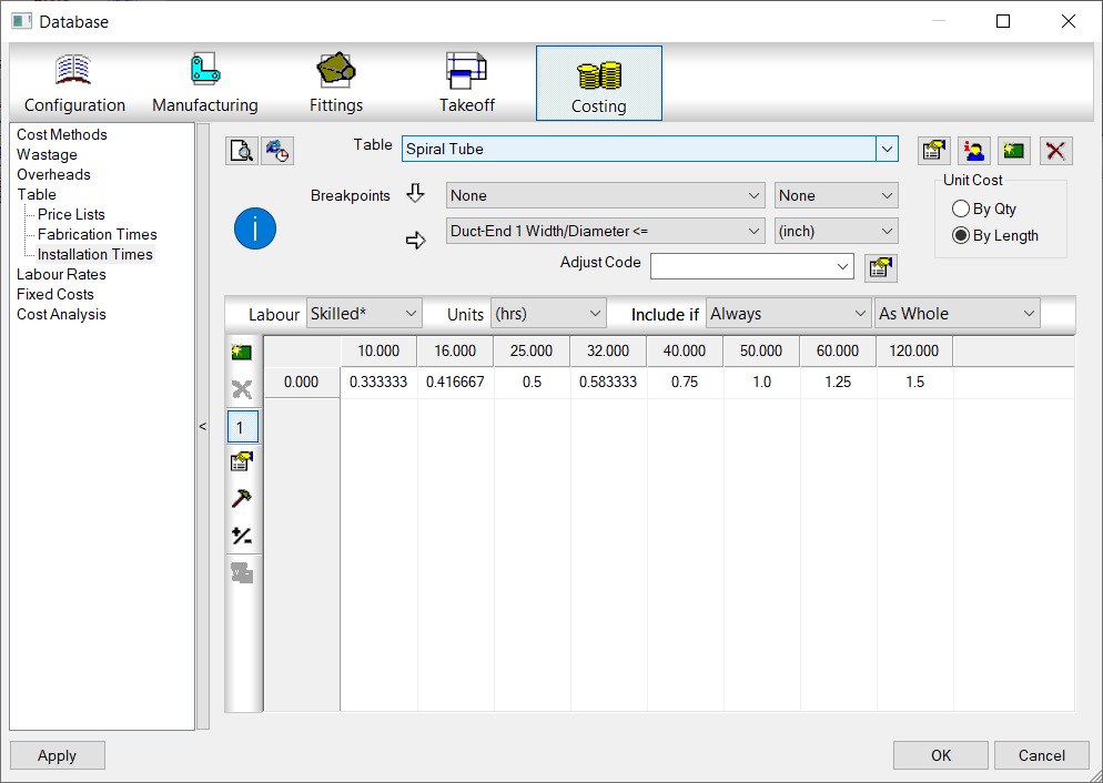
Similar to a Price Breakpoint, you can make a matrix for Labor as well. With Labor Breakpoints, you can also make more than one matrix and have it apply to various properties of the item labor is being applied to like Insulated or Non-Insulated.
Finding the Right Price & Labor Tables
While all you need for ProdInfo is an ID on an ITM and matching ID entry in the ProdInfo Database, Price and Labor need an extra step.
Price and Labor can have multiple tables to help you organize the values or even manage the price for the same item from multiple suppliers. To handle this, you set the tables in the ITM properties. This is true for both Product Listed ITM’s as well as Non-Product Listed ITM’s.
Setting these tables tells Fabrication which table to look in to find either the ID or the Breakpoint table which uses size and property criteria to apply to the ITM.
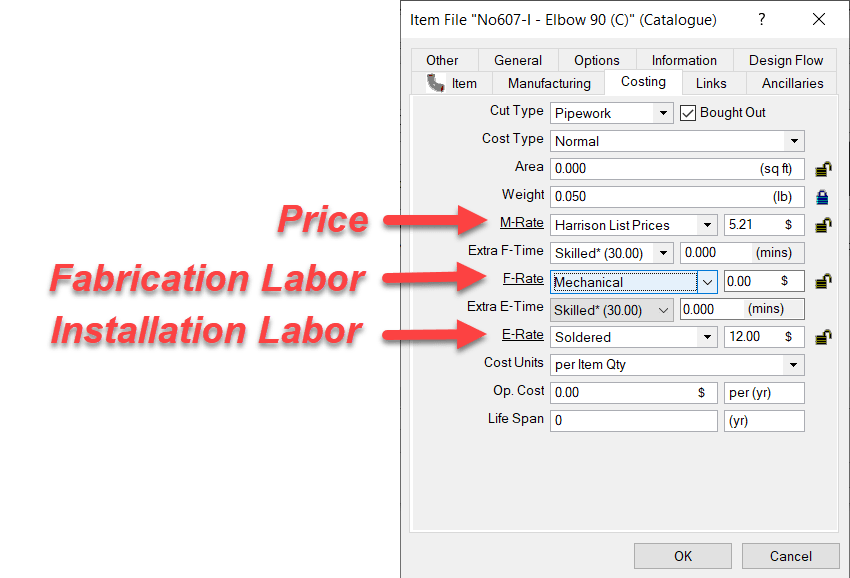
The following image shows where those tables are configured in the Costing tab of the ITM properties.
M-Rate is were the Price of the material comes from. This is set typically for bought items where you pay a set price. If you leave this set to “None“, material pricing would be calculated on a “Price per Pound” formula based on the material weight. This is typically done for Fabricated Sheetmetal fittings where the weight of the Sheetmetal is calculated based on area and gauge and then priced per pound. For piping or bought items, this table would typically point to a table that contains the pricing.
F-Rate is where you select the Fabrication Table to use to look up the Breakpoint Table or ID if Product listed labor. This is most commonly set to “None” for Piping items or other bought items where you just buy them but don’t fabricate them. It’s usually set to a specific table for Sheetmetal fittings which you fabricate and want to calculate fabrication labor.
E-Rate – This table is for Installation Labor. The “E” in “E-Rate” stands for “Erection” if that helps you remember. This will be set for most contractors who are installing duct or piping. It would typically be set to “None” if you were a fabricator only selling to others who install.
Summary
Hopefully this helps give you an idea how pricing, labor and product information functions (at a high level) in Autodesk Fabrication. There’s a lot more strategy and nuance you can get into but this is a good place to start understanding the basics of how it all works.