If you’re an AutoLISP programmer and use Autodesk Fabrication CADmep, you most likely know that there’s a COD Scripting language in Autodesk Fabrication that provides read and/or write access to CADmep properties. The problem with COD Scripts, is that sometimes they’re not powerful enough to do all of the other things you’d like to do and you may want to use AutoLISP.
What you may not know is that you can access the vast majority of CADmep properties from AutoLISP. To so this, you need to configure CADmep’s List Setup dialog which will provide a light weight but similar interface to what you see when you build reports in Autodesk Fabrication.
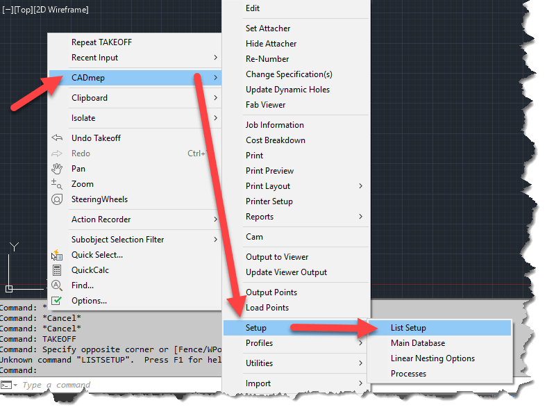
To access List Setup, right-click in an open area or the drawing editor and then select “CADmep” -> “Setup” -> “List Setup” from the menu.
ListSetup will Provide access to CADmep Properties
Configuring List Setup will provide access to the configured properties via DXF codes which are one of the most common ways of accessing object properties in AutoLISP. (You can also access these same DXF based properties via VBA, ARX or .Net)
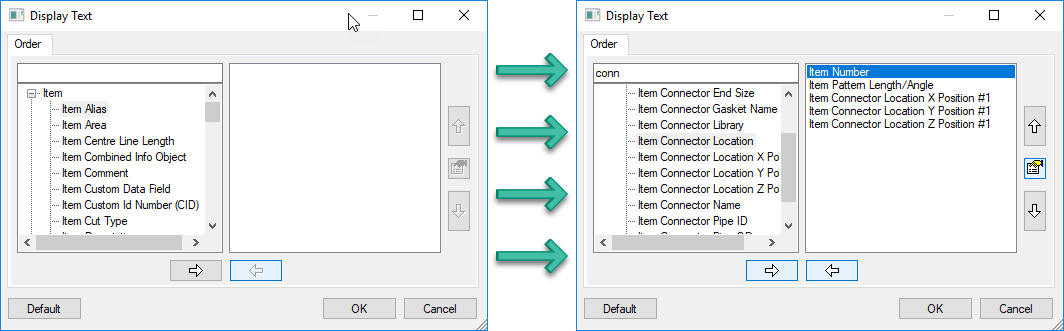
The following image shows the List Setup dialog before (left) and after (right) being configured. Simply add the properties you want to extract in the order you want them.
Before and After Configuration of List Setup
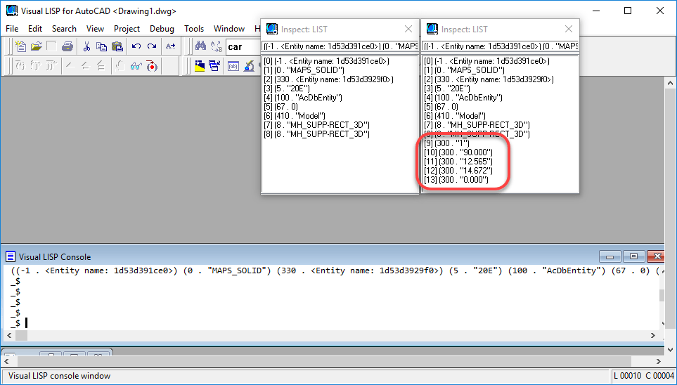
Once you’ve configured the properties you want, a simple call to the (ENTGET) function in AutoLISP will return the data you’re looking for. You can see in the following image, that we’ve saved the DXF data to two different variables in the VisualLISP editor. The listsetup-blank variable (left) was done before configuration and the listsetup-config variable (right) was done after the configuration of List Setup.
CADmep Properties can be Found in the 300 DXF Group Codes
The code used to extract the data is the following….
Because the VisualLISP editor does not word wrap it’s results, you can use the Inspect
Now, there are a few things to know about this method….
All CADmep properties show up in DXF Group Code 300. If you are returning multiple properties, you’ll have multiple 300 codes to parse through.
The order the properties are configured in List Setup is the order the properties will appear when returned in AutoLISP. There really is no other foolproof way of knowing which codes are which properties (unless obvious by their value) without knowing the order List Setup was configured.
If you later change the properties or their order, you’ll likely break your existing code. Think carefully about what you may want later and add it from the start even if you don’t want it at this time. If you need to add properties later, simply add them to the end of the list.
This method works well for reading Fabrication properties. It doesn’t allow you to set them using functions like “(ENTMOD)” or “(ENTUPD)“
After a very brief appearance toward the end of October, the Fabrication updates for 2018.3 and 2019.1 are back on line as of today.
Unlike previously speculated, they were not removed due to issues. They were intended to be released later but were inadvertently released early. If you happened to have them from their initial release, you don’t need to download the update again, the build numbers did not change. However, the PDF documentation of fixed issues on some of them did get more information listed in what was fixed. You can review all the issues addressed here…
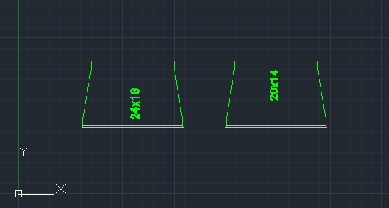
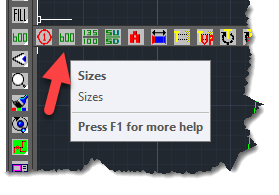
In CADmep, using the Size command, you can tag the size of a fitting. But on a fitting like a transition, what if you wanted to tag the size of the opposite end?
This can be easily done but the sequence is a little nuanced. Type “SIZE” from AutoCAD’s command prompt or select the “Size” tool button on the CADmep toolbar.
When prompted to Select Objects, select the fitting. Once the fitting is selected, instead of pressing <Enter> to end the selection like you normally would, press and hold the <TAB> key while you press the <Enter> on the keyboard at the same time. Your tag will display the size of the opposite end.
Depending on your AutoCAD and Mouse settings, right-clicking to end the select objects prompt may not work and instead bring up a right-click menu. For this reason, it’s recommended you use the <Enter> key on your keyboard while pressing <Tab>
The following video shows to transitions of the same size side by side. The left transition has it’s size tagged like you normally would. The fitting on the right, the <Tab> key his being held down when the <Enter> key is pressed which results in the tag displaying the size of the opposite end of the fitting.
On October 23 2018, Autodesk released Update 2019.1 and 2018.3 for all the Autodesk Fabrication products. Within a week, the updates have disappeared. This most often happens when a critical issue arises with the update. No word on what it may effect but when this has happened in the past, the issues were often significant.
I have not taken the time to uninstall and reinstall my Fabrication products as I don’t do production work. I would advise anyone that does production work to seriously consider this if they’ve already applied the updates.
So far with the limited Fabrication database administration I’ve done I haven’t noticed anything. I have tested nearly 1-1/2 dozen support issues I’ve logged over the last year and a half and only 1 was addressed. Many of my issues affected incorrect sheet metal pattern developments and require manual fixes each time.
If you’re interested in the issues that were suppose to be addressed, please refer to my Fabrication update page. Links are below. If past history holds true, the new updates will come out a month from now and be new versions which may not list the issues that were corrected.
I’ve been asked from time to time, which Autodesk Fabrication Patterns (CID’s) support exporting points for field layout. If you want to use Trimble, Topcon or similar hardware for field layout like hanger inserts for MEP, these points are important.
So, with this post, we’ll show you that information but also hope to accomplish something else in the process. I’ll walk you through a couple ways to do it, one significantly better than the other. It’s not really important that you know how to do this same process again, once you have the information, you’ll likely save it somewhere. However, knowing how to do this process will hopefully give you ideas about techniques you can use for other types of data mining and extraction. It’s not hard after all, you just need to get creative with few things you already likely know how to do.
If you’d rather just get to the data, scroll to the end of this post and you’ll find the list of pattern numbers. Otherwise, follow along and at the same time, explore some options for learning how to get this type of data yourself.
Step 1 – Get a copy of Every CID
The MAKEPAT command in Fabrication is how we create new ITM’s based on a particular CID. Most people working with Fabrication for a while know that. What they may not know is that you don’t have to randomly type patter numbers and run the command hundreds of times. CAMduct can do them all at once. If you don’ have CAMduct, install a trail version which you can download from Autodesk’s web site.
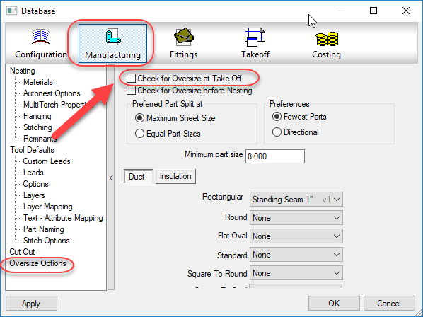
After starting CAMduct with a new project, the first step is to turn off prompting for Oversize which would keep prompting you on some large sheet metal patterns that exceed the material size. We turn this off to make the process run without pausing for user input.
Turn OFF Oversize Checking
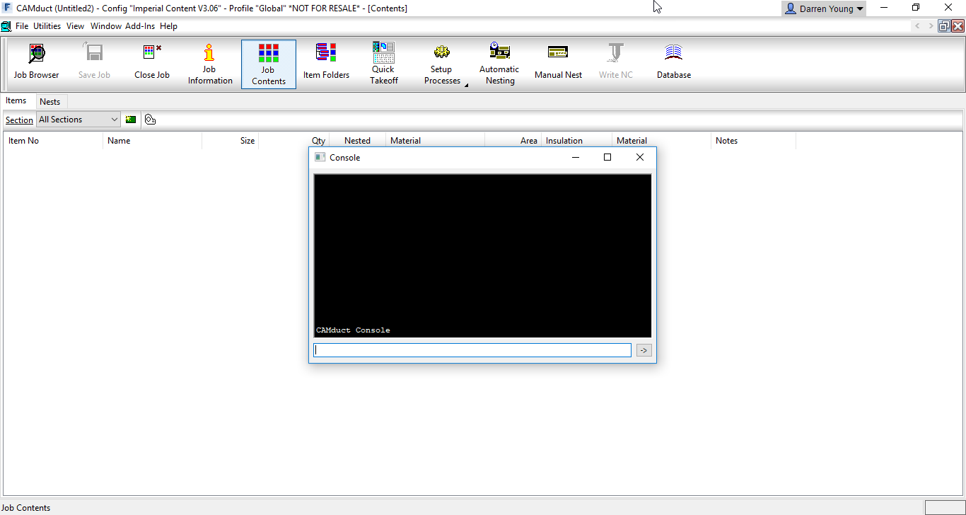
The next step is to display CAMduct’s Command Window screen by pressing “CTRL-SHIFT-C“.
Pressing “CTRL-SHIFT-C” on the Keyboard Displays the Command Window.
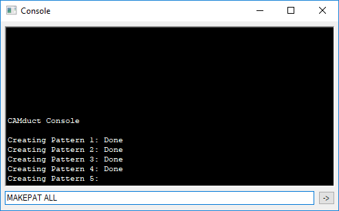
Next, in the Command Window, type the command “MAKEPAT ALL” and press <Enter>. (Note that the Command Window is also part of ESTmep but the MAKEPAT ALL function is not supported in ESTmep, only CAMduct.)
“MAKEPAT ALL” will Create One of Each Pattern
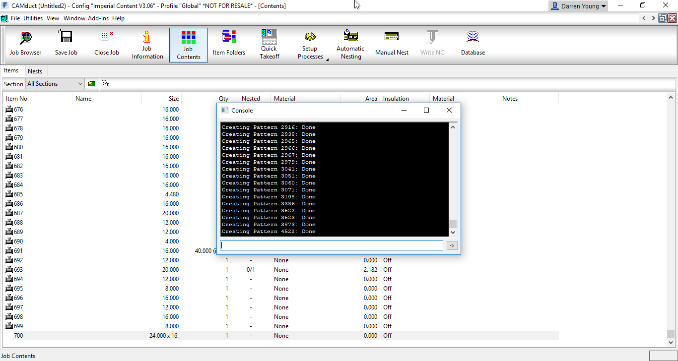
Depending on the speed and resources of your computer or even other running processes, this can appear as if it’s locked up CAMduct at times. However, be patient and let it sit. Unless the software crashes, the process will complete. I’ve seen cases where it can take over 10 minutes or more.
When complete, there is no prompt. You’ll just notice the cursor back in the Command Window’s typing area. The last pattern should be CID 4522. You’ll also see the Job Contents will contain each pattern that was successfully taken off. These patterns exist only in this job, not in your database so you’ll want to save this job in CAMduct’s MAJ file format for future reference. If you like, you can download my copy here.
All Successful and Supported CID’s Are Now in One MAJ.
Step 2 – Examine Patterns
Now that we have a file with all the patterns, we can examine them. There’s a lot, and doing each one individually will take a lot of time. If you’ve ever been to one of my Autodesk University sessions, you’ll know that I frequently supply a lot of Fabrication COD scripts. This is where they can come in handy. You can download them here.
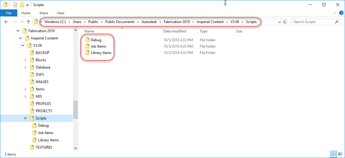
I typically place my COD scripts under the Scripts folder in my Fabrication Configuration like so…
Scripts Extracted to the Configuration’s “Scripts” Folder
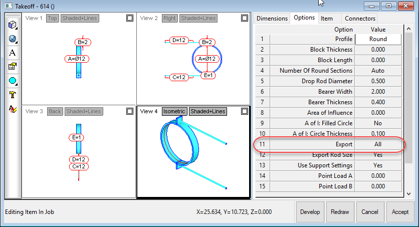
If you look at a Hanger CID (1249 for example) you’ll see in it’s Options tab that there’s an “Export” option that tells CADmep if it should export field layout points or not.
The “Export” Option Controls Field Layout Point Exports
We’ll use this to determine which CID’s export points which is where the scripts come in. For this example, we’ll be using the following script…
.\Scripts\Job Items\WriteAllOptions (Job).cod
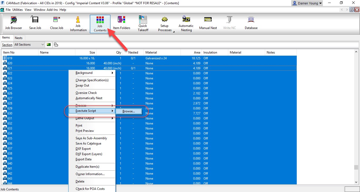
This script will write all the Options for all the item in the CAMduct Job. To do this, click the Job Contents button on the ribbon, select all the items in the job, Right-Click and select the Execute Script option then browse to the above referenced COD script.
Use “Execute Script” to Run a COD Script on All Selected Items
After the script completes, it’ll have written to a text file all the options and their values for each of the items in the job along with their CID. You can find the file located in the root of your fabrication configuration’s Items folder. This is the file you’ll be looking for…
.\Items\WriteDWGOptions.Txt
Using Microsoft Excel, open the text file. Make sure you change the file extension to Text Files so Excel displays the file you created.
Change Excel’s File Type to “Text Files (*.prn;*txt;*.csv)“
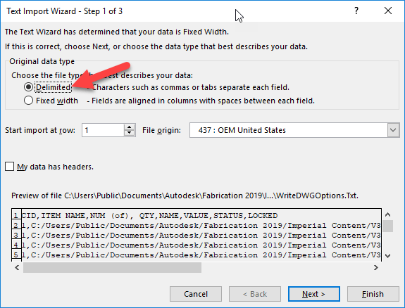
This will bring up Excel’s Text Import Wizard. Select the “Delimited” radio button and click Next.
Use “Delimited” as the Import Option in Excel
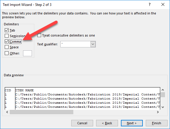
In the next screen of the Wizard, you’ll select the “Comma” toggle as one of the delimiters and then click the Next button.
Use the “Comma” Option as the Delimiter
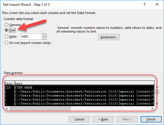
In the next wizard page, you’ll highlight all the columns in the bottom portion and select the “Text” radio button to tell Excel to treat all the columns as text. From there, click the Finish button.
Change All Columns to “Text” Data Format
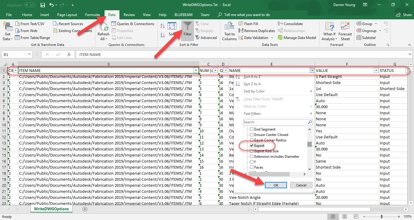
From here, Excel displays a line item for each option of each item in the job. You can now quickly filter this list by clicking the Data ribbon menu and selecting the Filter button. This adds a drop down arrow control in the first row of each column. “Column E” is the “Name” of the option. When you click the drop down arrow in that column, you see a list of all the values. Uncheck the top “(Select All)” option to deselect all the values and then scroll to the “Export” option and select it. This tells Excel to only display rows containing this text. From here, click the OK button.
Use AutoFilter to Display Only the Rows that Contain the “Export” Option
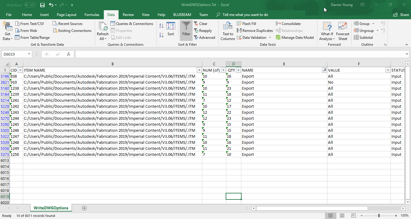
Once this is done, you’ll get a very short list in Excel. The left most column, “Column A“, is the CID or Pattern Number for each item in the job (we make one of each pattern) that has the Export option.
Excel Quickly Filters Options to Only Those With an “Export” Option.
So now we have a list of Pattern Numbers that you know will export points for field layout. You also learned how you can use some of the scripts I have to Export and mine data from your fabrication configuration. The question you have to ask now is, are we certain this data is correct?
Autodesk Fabrication allows you to rename Dimension and Option names. That would suggest that it’s possible to miss an option that was renamed to something other than Export. In this case, because we used CAMduct to create all the patterns from scratch, it’s most likely that it’ll have all the default names for it’s Options and Dimensions.
We’re still not in the clear however. It’s possible some patterns that support field layout points don’t have an Export option or have a similar option but name it something else. For this reason, we can’t be certain we know ALL the CID’s but we can be certain that we know SOME of them.
Step 3 – An Second (Better) Approach
How can we be certain we know ALL the CID’s that support field layout point exports? The simple answer is to export all of the items and see which have points.
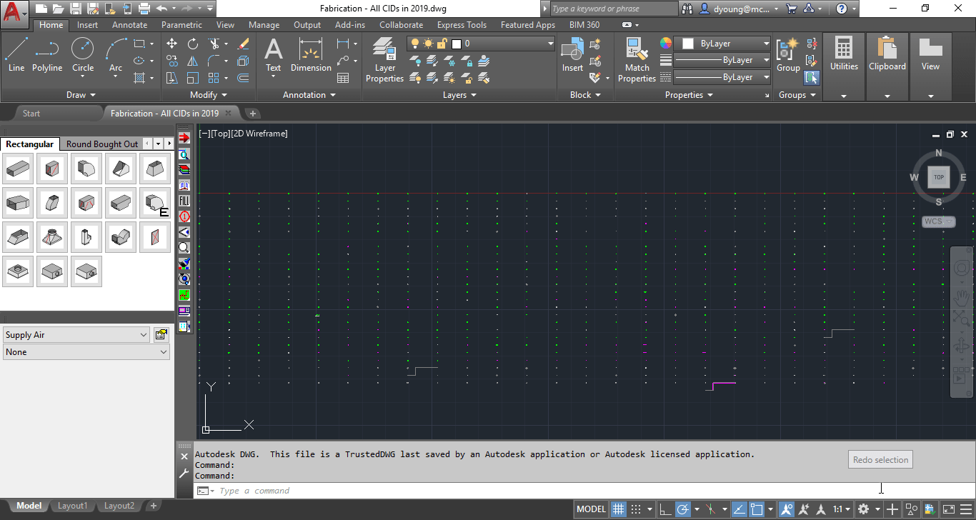
To do this, we can use Fabrication CADmep. Start AutoCAD and load Fabrication CADmep. From here, if you saved the job you created in CAMduct as an MAJ file, you can use the “OpenJob” command in CADmep to import all those Items into CADmep.
CADmep will display all the items in the Fab Viewer before importing. Simply click the OK button to complete the import process.
MAJ Imported into CADmep Displays Items in an Array
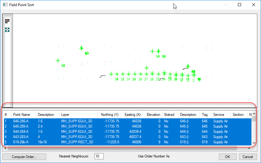
Once the MAJ is imported, CADmep will display all the Items in a large array. From here, we can use the “FPOINTE” command (previously the “TRIME” command) to export all the points. When the command asks you to select the points, type “ALL” at the select objects prompt. This will display the Field Point Sort dialog.
All Items Supporting Field Point Exports Will Appear in this Dialog.
Now we could finish exporting the points at this time but we’re not going to. This is because not all the information in this window actually gets exported. Specifically, the Tag column which displays the Item number (not the CID) and we need to know which Item number (which CAMduct sequentially numbered) to find the Item so we can check it’s CID later.
Instead, we’re going to select all the points in the bottom of the dialog, Right-Click and select “Copy” to copy the entries into the Windows Clipboard.
Without going into all the steps here, the next thing we naturally want to try is to Paste the items into Excel. If you go ahead and try it, you’ll likely notice that the coordinate fields are missing (that’s an interesting story with some history in itself) which isn’t a big deal for our purpose. But upon closer examination, you’ll also see that the columns aren’t lining up in Excel. Pasting this data into Excel is not going to work without a lot of fixing of data.
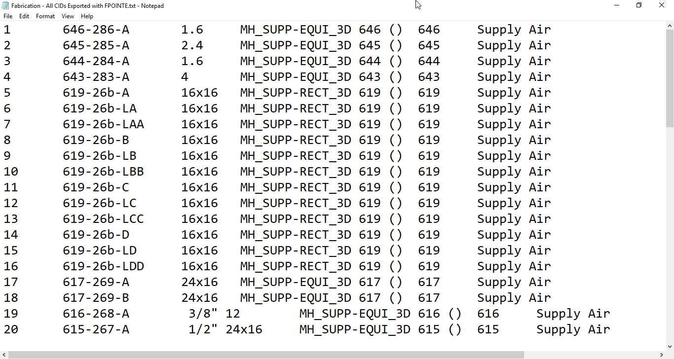
So the next thing I try, I paste the data into a blank Notepad file to see what it looks like there.
“FPOINTE” Data Pasted Into Notepad
Looking at the data in Notepad, you can easily see there’s columns. A little lower in the file you see the columns tend to shift, bit there’s definitely columns there. A little further experimentation using the cursor and keyboard arrow keys you can see the cursor jump between columns. This is a clear indication that columns are separated with Tab character. If your data doesn’t look like this, try looking at the Word Wrap setting in the Format pull down menu and turning it off.
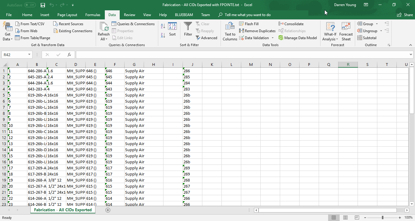
At this point, you should be guessing what’s next. Save the TXT file and open it in Excel like you did earlier. The only difference is that instead of selecting a comma as a delimiter, you want to make sure that Tab is selected as the delimiter, The resulting data in Excel should look like the following image…
“FPOINTE” Data Opened in Excel
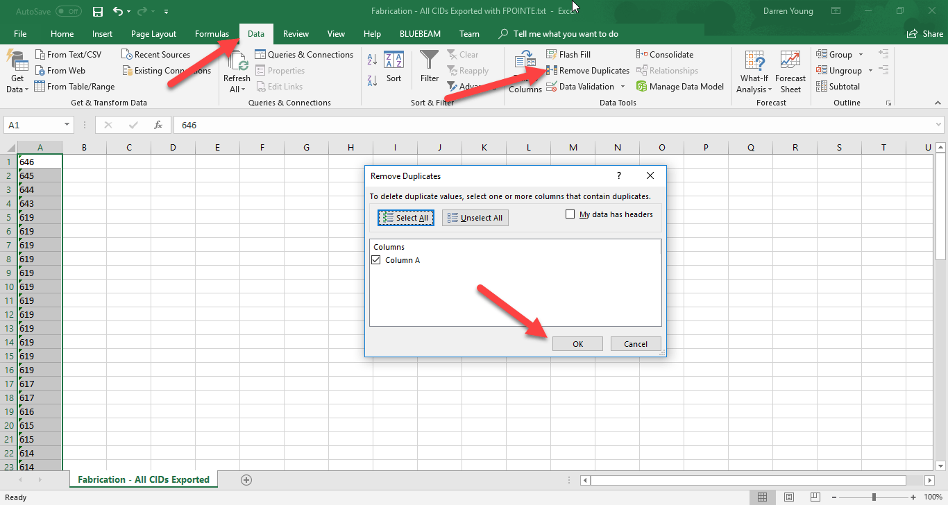
Lets keep in mind that some patterns export more than one point so there’s duplicates that aren’t needed. Additionally, we really don’t care about any of the exported data except for the Item Number which was in the Tag column in the Field Point Sort. This column is in Column F of Excel. For this reason, we’ll delete all the columns except for F. When you’re done, Column F will shift to Column A. From here, we can use Excel’s Remove Duplicates function on the Data ribbon to remove the duplicate Item Numbers.
Remove All Columns Except the One With the Tag Data and Run Remove Duplicates
When you’re done, you’ll have a nice short list of each pattern’s ItemNumber that was able to be exported. Note, this is the sequential Item Number that CAMduct assigned when creating the patterns. This is NOTthe CID or Pattern Number. Keep this Excel file opened for now, we’ll get back to it later.
At this point, it wouldn’t be too hard to look up each item number in CADmep or CAMduct and check it’s properties to find the Pattern Number of the item. But that can still take some time. We’ll go through another step to automatically look up the Item Number and show you the Pattern Number of the Item.
Step 4 – Using The Item Number to Find The Pattern Number (CID)
We need to somehow tie the Item Number to the CID or PatternNumber. To accomplish this, we’ll again turn to our scripts. All of my COD Scripts typically export the CID number. There’s also typically a script for each property. So we’ll be using the following script which will export the CID and Item Number of all the items in our drawing.
.\Scripts\Job Items\WriteAllNumbers (Job).cod
Type “ExecuteScript” in CADmep and browse to the above script file. At the Select Objects prompt, type “ALL” to select all the items in the drawing to run the script on. When the script is finished, it’ll export the data to the root of the Items folder like before. Open it just the same as you did prior making sure you use a Comma for a delimiter and change the column data types to Text.
.\Items\WriteDWGNumbers.Txt
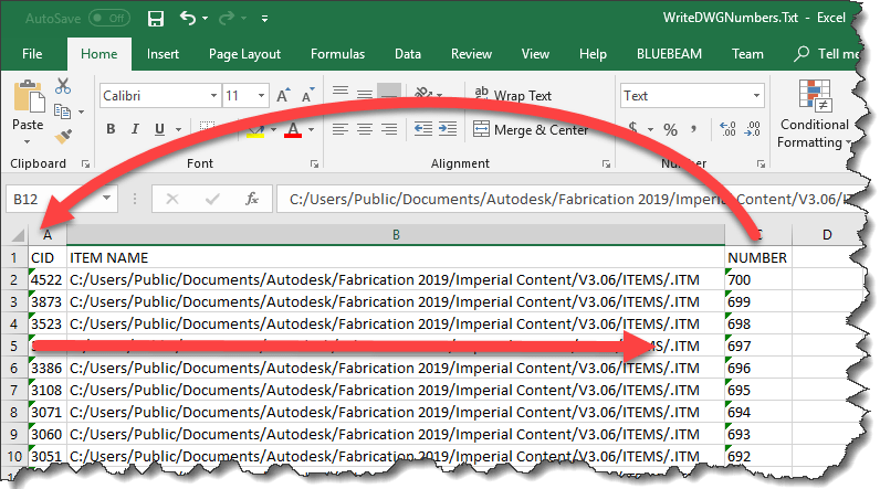
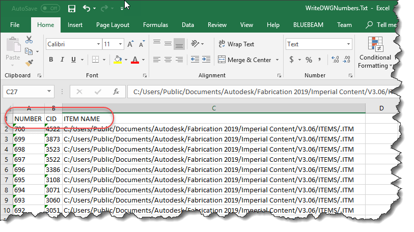
Once you open the Item Number export file, it’ll look like the following image. This is what we’ll use to cross reference the Item Numbers with their corresponding Pattern Number.
Item Numbers Exported from our Job
Because we need to look up the Item Number in Excel, we’ll want to move the Number column in front of the CID column. This is because the function that we’re going to use in Excel needs the number it’s looking up in the first column. When complete, your data should look like the following image…
Number Column Moved To The First Column
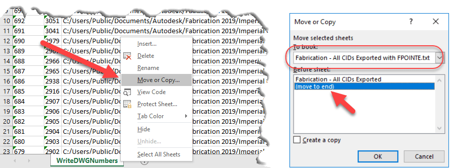
Next, we’ll move this entire worksheet to the first Excel file that contains our points. Right-Click on the worksheet tab and select “Move or Copy…“, use the drop down list in the Move or Copy dialog to select the spreadsheet with your exported point data and move it to the end. Click OK when done. This will move the sheet with exported Item Numbers and CID’s to the end of the other workbook.
Move the Exported Item Numbers Worksheet to Your Point Export File
When you’re done, you’ll have two separate tabs in your first Workbook. One lists only the Item Numbers of the successfully exported points, the other contains the Item Numbers and corresponding CID’s.
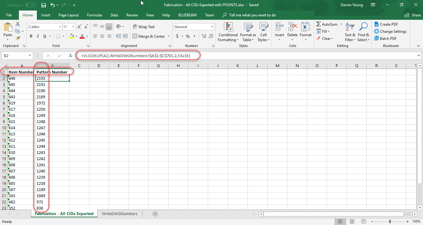
Go to the first worksheet tab where it lists a single column with the Items Numbers that were exported. Add a blank row at the top and type the text “Item Number” in Column A and “Pattern Number” in Column B. In cell B2, type the following formula…
=VLOOKUP(A2,WriteDWGNumbers!$A$1:$C$701,2,FALSE)
After typing the formula, copy it to the remaining cells in the column to complete the cross reference.
This formula tells Excel to look at the ItemNumber, and find it in the first column of the range in the second worksheet that lists all the ItemNumbers and CID’s. When it finds that corresponding ItemNumber, return the value from the second column which contains the CID. The “$” in the cell address of the range tells Excel to NOT increment the range address as the formula is copied down…you want to look at the same range no matter what. Finally, the False flag tells Excel to do a strict match and not try to interpret close results. Your finished data should look like the following…
This completes our final list of Pattern Numbers (CID’s) that support Field Point Exports. You can look at my Excel file by downloading it from here.
Note that when we looked only at Items that contained the Export option, there were 14 patterns. However when we tested against the actual point export in CADmep, we ended up with 25 patterns. Our final list of PatternNumbers (CID’s) that support field point exports is here…
149
321
322
838
972
1049
1189
1238
1239
1240
1241
1242
1243
1244
1245
1246
1247
1248
1249
1250
1972
2189
2190
2191
2192
Hopefully you’ve gained an idea on how to use some of the scripts, Excel and other processes to mine and extract data from your Fabrication configuration. It’s using techniques like these that allow me to assemble a lot of the information I have on this site like which versions of software have which CIDs’s and which ones are supported in Revit.
Autodesk Fabrication reports can be tricky. It’s not always clear what’s happening with the data you’re trying to report or where it’s coming from. To make matters worse, some print objects are listed more than once.
These duplicate print objects are not just in multiple categories for you’re convenience when building reports. In fact, they don’t even report the same information.
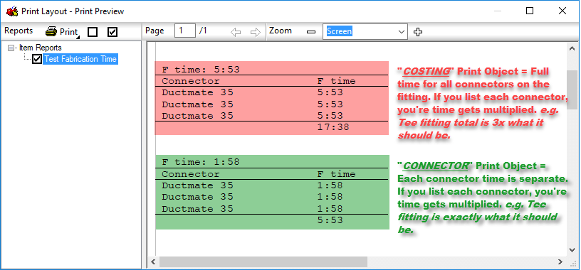
In this example, we’ll look at Item Connector Fabrication Time as it applies to a Tee duct fitting, Each Tee fitting has 3 connectors which we’ve set to a Ductmate connection. We’re using this connector because it has labor attached to it in the default Imperial configuration that Autodesk ships with Fabrication CADmep, ESTmep and CAMduct.
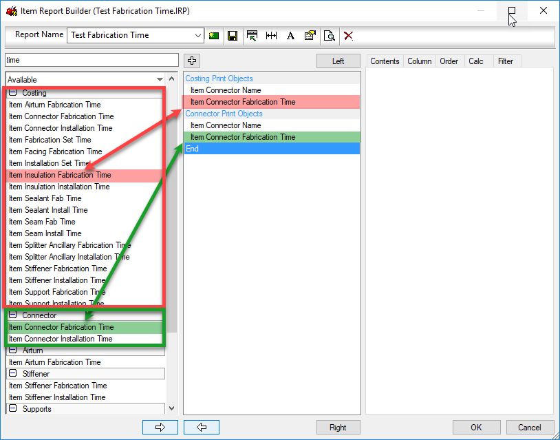
The following image shows our report editor for an Item report. The Red and Green shows the same name for the print objects. One is located in the Costing group and the other in the Connector group.
Red and Green Print Objects are the Same Name but from Different Groups
The “Costing: Item Connector Fabrication Time” print object returns the time for ALL the connectors on the fitting. The “Connector: Item Connector Fabrication Time” print object on the other hand return the fabrication time for each connector individually.
The next image shows the preview of our Item report. Costing Print object is in the top table (red) and the Connector print object is in the bottom table (green).
Top (red) Table is Showing 3x the Fabrication Time as the Bottom Table.
Now, there’s nothing really wrong with the top (red) table that uses the Costing print object except one thing. The Connector Name print object is located in the Connector print objects group which is based in “each” connector”. Using the Connector Name will list the connector 3 times, but it;’s mixed with the print object from the Costing group. This means that the table, shows 3 rows, one for each connector (Name) but the Fabrication Time for each connector listed, is the total for the entire fitting. When totaled, this results in a Fabrication Time 3x more than what it should be for the Tee fitting we used as an example.
You can download a Zipped copy of the IRP used for this test here. Just unzip the *.IRP file and copy it to the folder for your reports in your Fabrication configuration.
To recap, be very cautious about grabbing the first print object you see in a report when you scroll through them. There may be duplicates and they could yield different results. Once added to your report, it’s very difficult to know where that print object was from without intimately knowing the differences between them.
For CADmep users, IFC has been a good way to get your content to other team members using Revit. While Revit now supports Fabrication Parts, exporting from CADmep to an MAJ for import into Revit hasn’t been a reliable way to share your model with Revit users. There are a couple of key reasons for this…
Not all Fabrication Parts in CADmep are supported
Import of MAJ files into Revit is very finicky and prone to failing.
For this reason, IFC Files have been a good way of ensuring all your Fabrication data gets displayed into Revit. And to be clear, this is by using the IFCE (IFC Export) command in CADmep. Note: AutoCAD MEP has it’s own IFCEXPORT command but this doesn’t handle Fabrication CADmep data well).
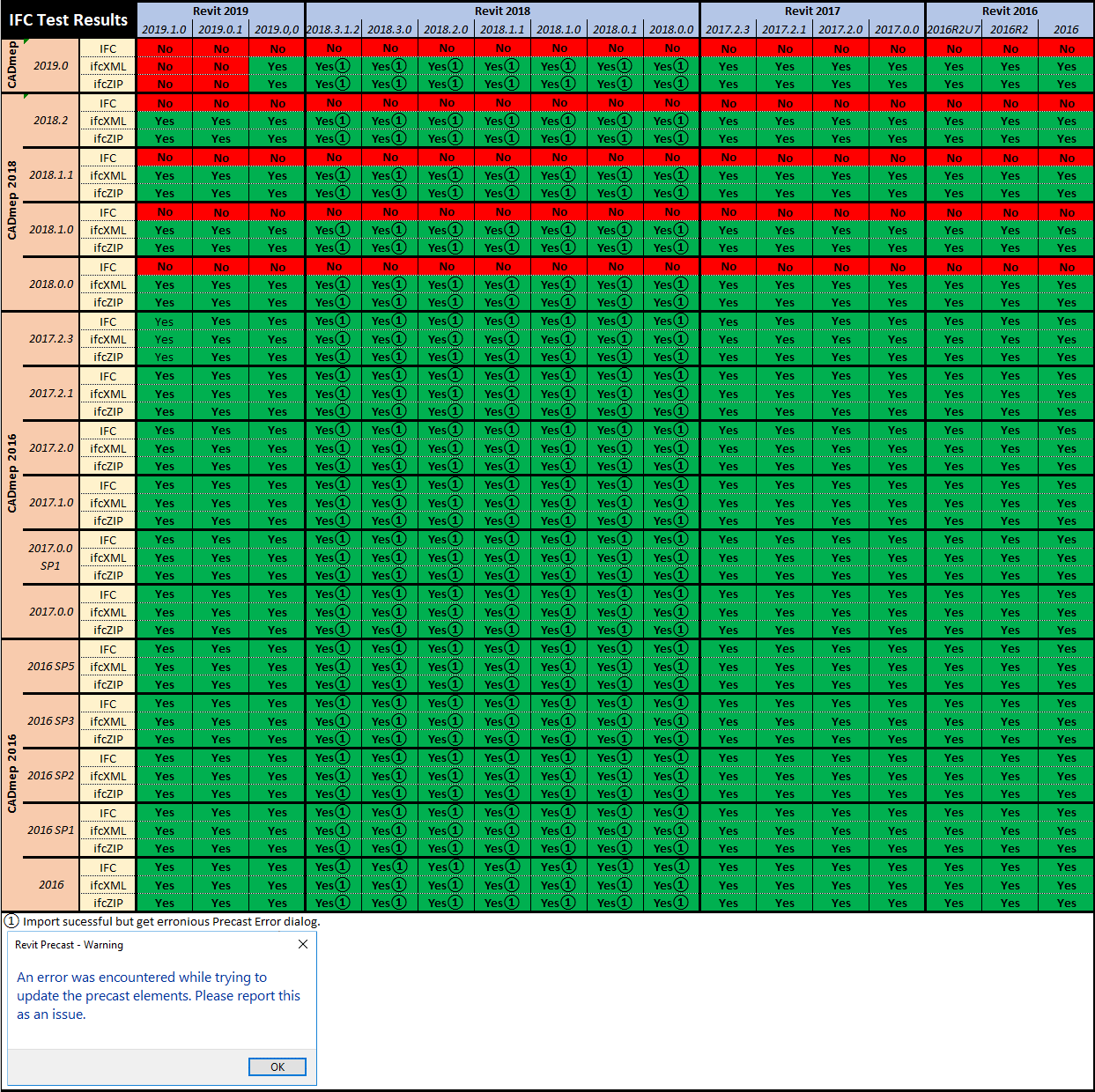
While IFC is a good way to get CADmep data to Revit and Navis, over the last couple of releases it’s been getting worse. Since 2018 release of CADmep, *.IFC files no longer import into Revit or Navis, For Revit, you can use *.ifcXML or *.ifcZIP formats but these worn’t help you with Navis which only reads *.IFC. And starting with Revit 2019.0.1 Hotfix, Revit will no longer read *.ifcXML or *.ifcZip either.
*.IFC Export from 2017 and earlier CADmep works in any Revit/Navis version.
*ifcXML export from any version of CADmep work in any Revit version before 2019.0.1
*ifcZIP export from any version of CADmep work in any Revit version before 2019.0.1
To help give you a better picture of IFC support from CADmep, please refer to the following two compatibility charts…
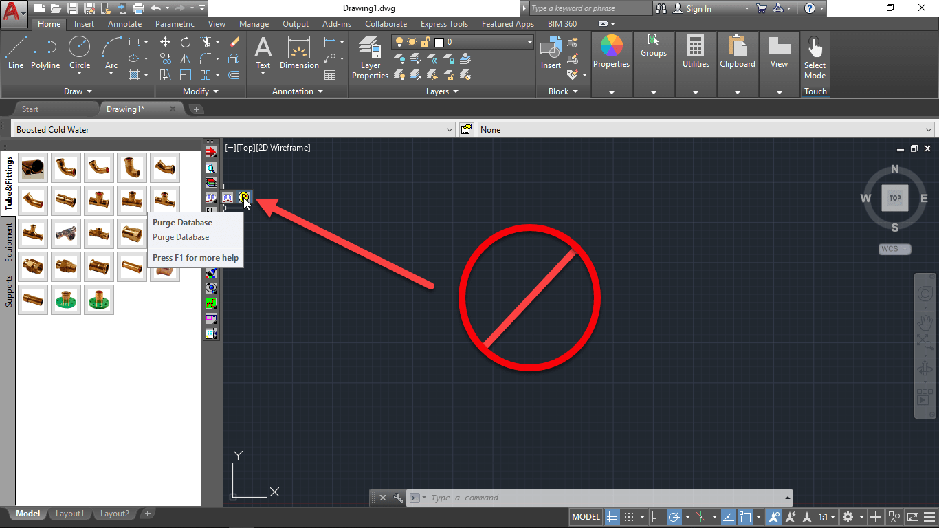
If you’re running 2019.0.0 versions of Autodesk Fabrication, you should be aware of this critical issue.
When using purging the fabrication database, the command will delete all of the content on your service templates leaving them with no buttons or content.
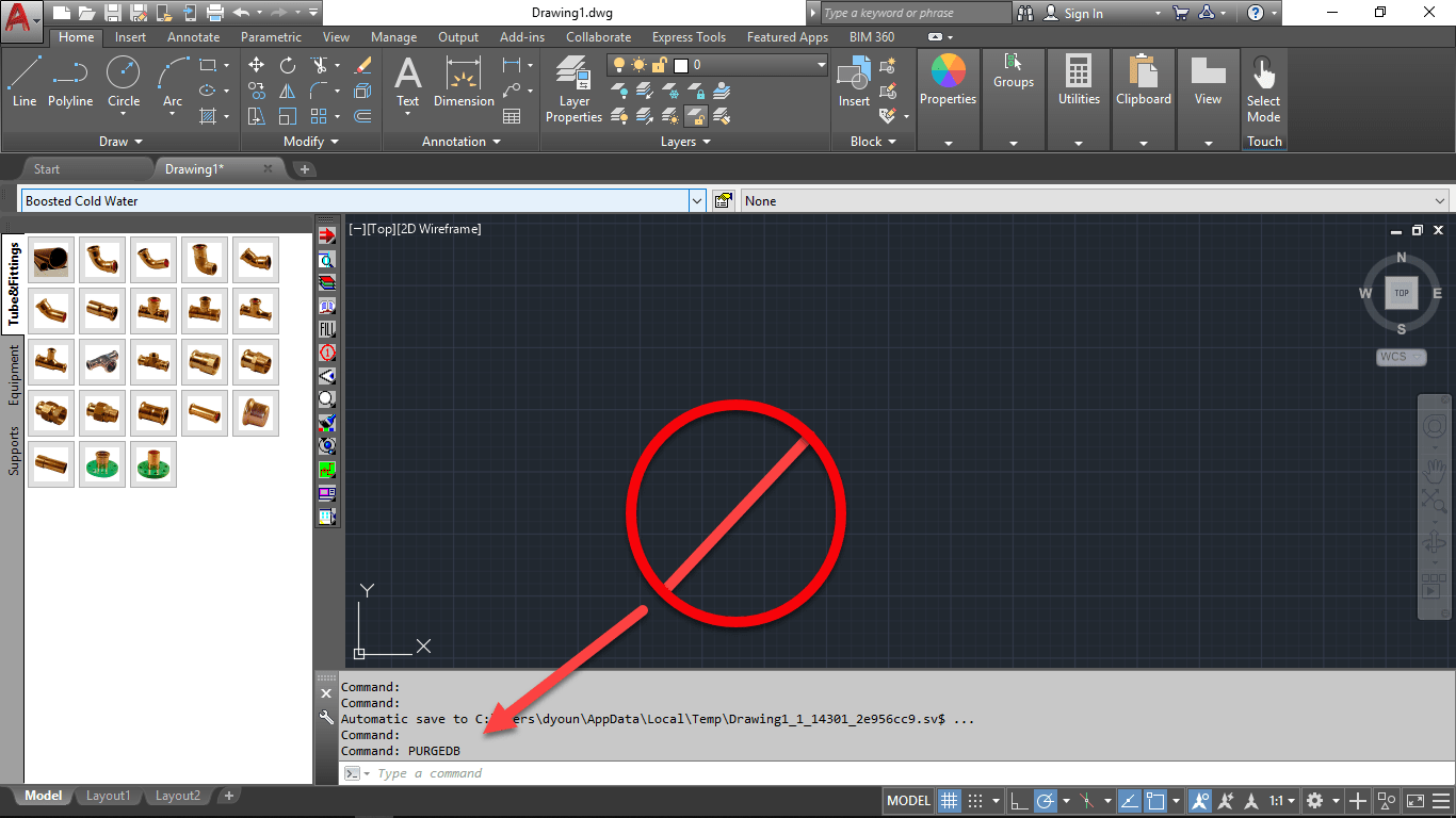
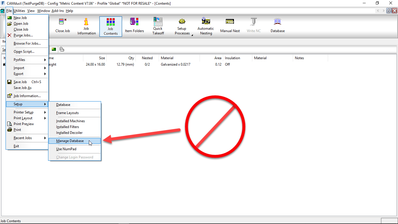
There are several ways to access this command. In CADmep, PURGEDB is accessed from the toolbar…
You can also type PURGEDB from AutoCAD’s command line.
From ESTmep or CAMduct, the functionality is accessed from the FILE -> Setup -> Manage Database menu.
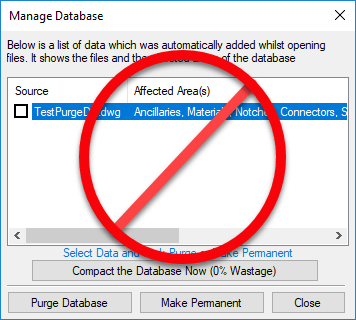
The Purge Database command itself displays the following dialog…
Again, in version 2019.0.0 versions of fabrication products, this will remove all content from all of your service templates. Do NOT run the command. Want to see for yourself what happens? Watch this Screen Capture…
This will only be a risk if you are logged into your database with Administrative privileges. In the event you have had this already happen, the only way to restore your services is to restore them from a backup of your database or to rebuild them all manually.
I’ve updated some of the Autodesk Fabrication Resources pages. You can find the links below however you should note that none of the information has changed from 2018 to 2019. Non the less, you can review the links here…
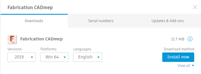
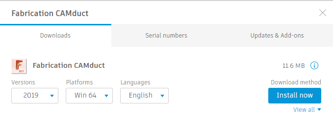
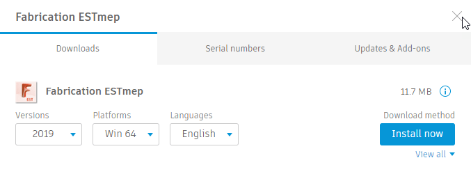
Autodesk released Fabrication CADmep, CAMduct and ESTmep 2019.0.0 this week. As they’re not primary products for Autodesk, they don’t always show up in the Autodesk Desktop App. The best place to get them is from the Product Downloads section of the Autodesk Accounts portal if you are a contract manager or software coordinator in your account.
For the most part, these are just repackaged versions of last year’s software. Autodesk’s focus is on adding Fabrication capabilities to it’s Revit product. None the less, there’s a couple new things that I’ll reveal in a future post.