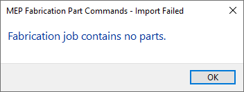
Have you ever tried importing an MAJ into Revit and received the following error….Fabrication Job Contains No Parts.
There’s a lot of reasons this can occur and it’s NEVER because there are no parts. So much for Autodesk’s QA/QC and Error checking.
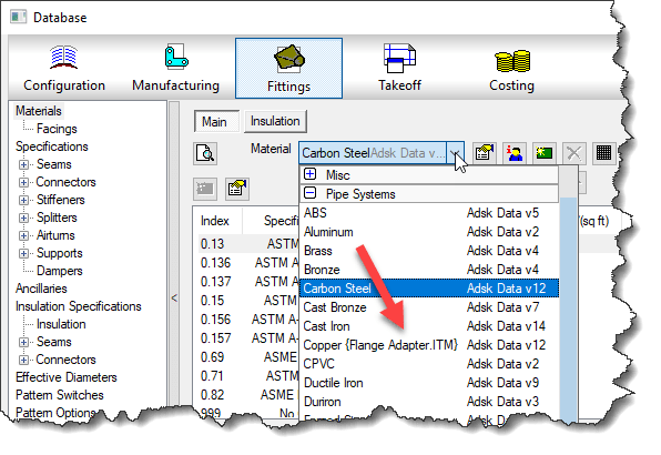
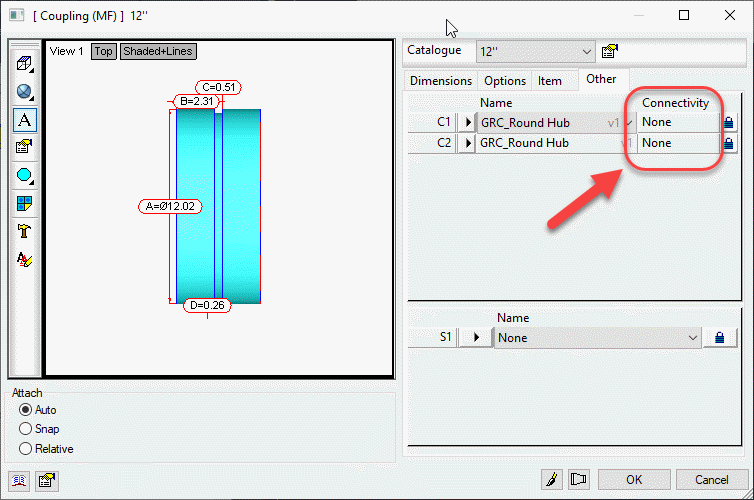
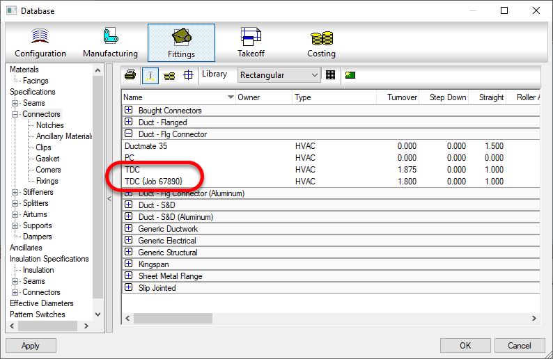
You may see this most commonly because parts used in the model contain data that’s no longer in your database. You’ve likely noticed from time to time database entries with curly braces around parts of the name like the following…
This happens when an entry in the database is used by an ITM but the database entry itself later gets deleted. Information is cached within the ITM so when it’s accessed, it creates a Proxy entry in your database if it was missing. Within the {Curley Braces} is the name of the object that created the entry.
While CADmep, ESTmep and CAMduct handle this fairly gracefully, Revit on the other hand does not. When it attempts to load an MAJ, it sees these entries and notices they’re missing from your database and prohibits you from importing the MAJ file. Revit thinks the database doesn’t match the MAJ and stops you cold!
A Possible Fix
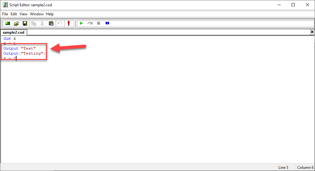
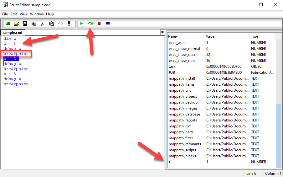
If this is cause for the import error, you can use the following COD script to potentially work around the issue….
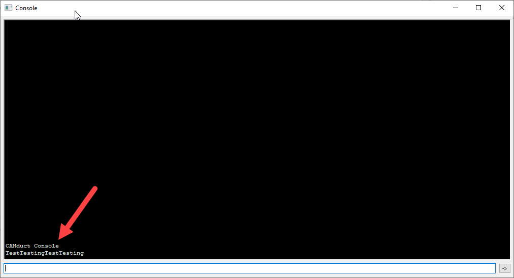
Take the following script and run in in CADmep, ESTmep or CAMduct. You should be logged in with Administrative Permissions while doing this. This script isn’t fixing Revit or the MAJ. What it’s doing is loading ALL the ITM’s from your Database Library into memory.
The process of loading all these ITM’s into memory creates all these proxy entries in your database. This way, when Revit attempts to import the MAJ, the data associated with those ITM’s are most likely present in your Database configuration. In many cases then results in a successful import of the MAJ.
If the Revit file you are importing the MAJ into already points to a Fabrication Configuration, you should reloaded the configuration FIRST before attempting to import the MAJ.
If for some reason this process still doesn’t work, verify that Revit is reading from the same database location as the version of CADmep, ESTmep or CAMduct where you ran the COD script.
In the event it still doesn’t work, there may be other reasons for the failure but this is often the most common, especially with MAJ’s created recently.
If it does work, you’ll want to use the other scripts I provide on this site to help analyze your database. You likely deleted those database entries in the first place for a reason. You either didn’t realize they were needed, or you didn’t know where they were used to repoint those ITM’s to a proper substitute. Those scripts can help you find which ITM’s use which database entries.
Hope this helps.