Fabrication 2023 is out. I’ve updated all the reference information to include 2023 formats. As has been the trend the last few years, little has changed. Summary below…
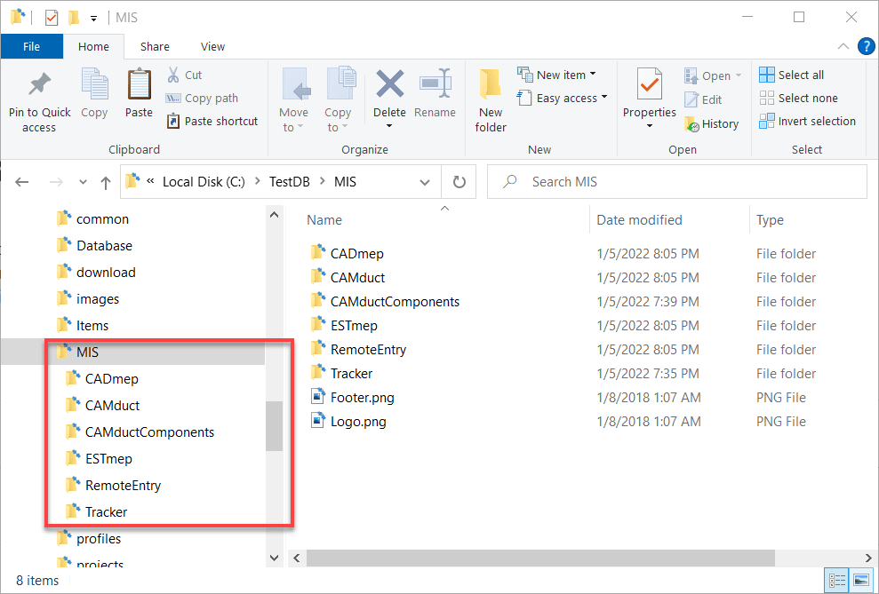
Those of you who used CADmep, CAMduct or ESTmep prior to it’s acquisition by Autodesk remember when all the reports were in one folder. Once Autodesk took over, they moved to a system where each product used a separate subfolder for their reports. After all, ESTmep is likely using different reports than CADmep and yet different than CAMduct. Here’s what your configured reports folders now look like (you may not have all products/folders). Notice how each product has it’s own older.
The reality is, many reports are helpful across products. This means you need to make the same report multiple times or copy it from one folder to the others. This leads to duplication of data and a chance than one of the copies gets changed different from the others.
Consolidating All Report to a Single Folder
It’s commonly asked if it’s possible to configure the different Fabrication product to use the same folder. The answer you always hear is No. Technically that’s correct. You can’t configure Fabrication products to look at the same folder. However….
You CAN configure Windows to make multiple folders look at the same folder. It’s just done at the Windows level with a feature called Junction Links.
So lets walk through how to configure CADmep, CAMDuct and ESTmep to all look at the same reports.
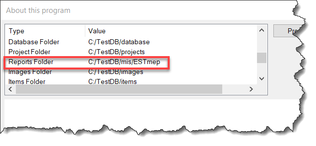
Step 1: Find Where Your Reports Are Located
Using CAMduct or ESTmep you can pick Help -> About or type AppInfo at the command line in CADmep. You can then scroll through the window to see where the Reports are located. Alternatively, you could use the Edit Configuration utility to find this folder as well.
Note that this screencap was done in ESTmep so you see the ESTmep subfolder. The mis folder is actually the root where all your reports are.
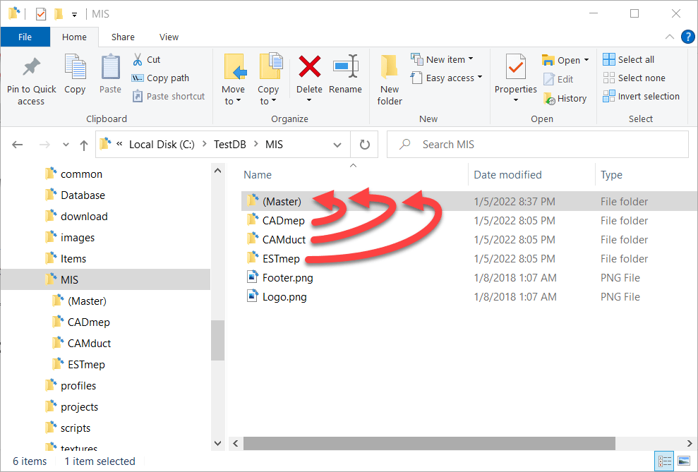
Step 2: Copy All Report Folders to a New Folder
The next step is to copy all the reports from the various product specific folders to a new master folder location to store the reports. In this case, we’ll call it (Master) just to make it super obvious. Notice we also deleted the folders for CAMductComponents, Tracker and RemoteEntry because I’m not using them. You can choose to include them if you need them,
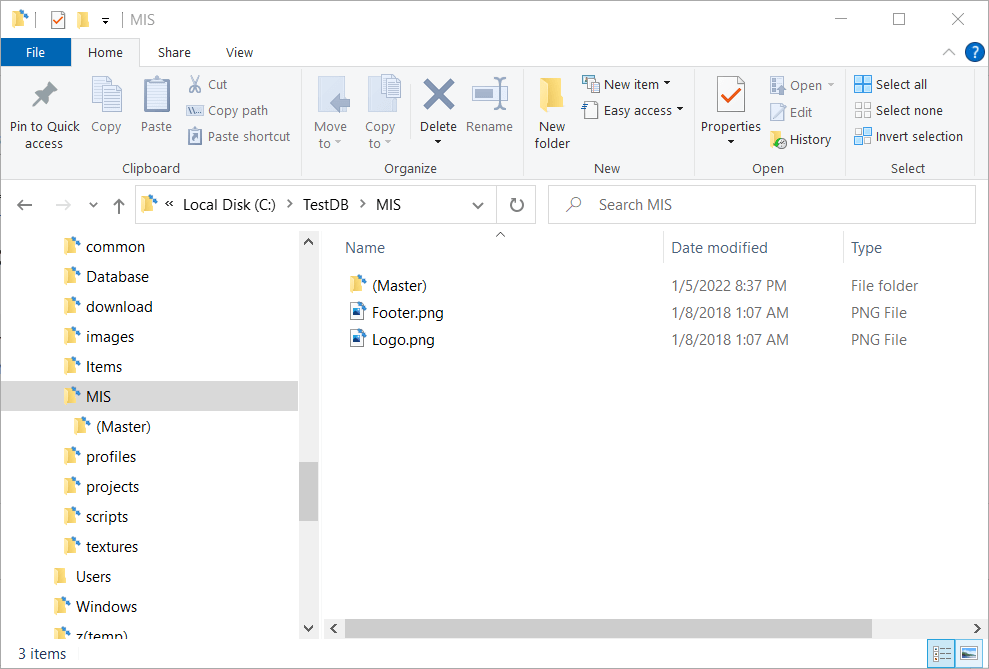
Step 3: Backup and Delete the Original Reports Folders
When you’re done, you should back a backup of the product specific reports folders elsewhere incase you want to go back to the original config. Once backed up, you need to delete the original product specific reports folders. When you’re done, your reports folders will look like this…
Step 4: Create Junction Links for the Product Folders
Here’s where we do the magic. Windows allows you to create what’s called a Junction to other folders. A Junction is just another virtual folder that looks at the contents of another. Junctions are how Windows has a “My Documents” folder that really points to “C:\Users\<Username>\Documents“.
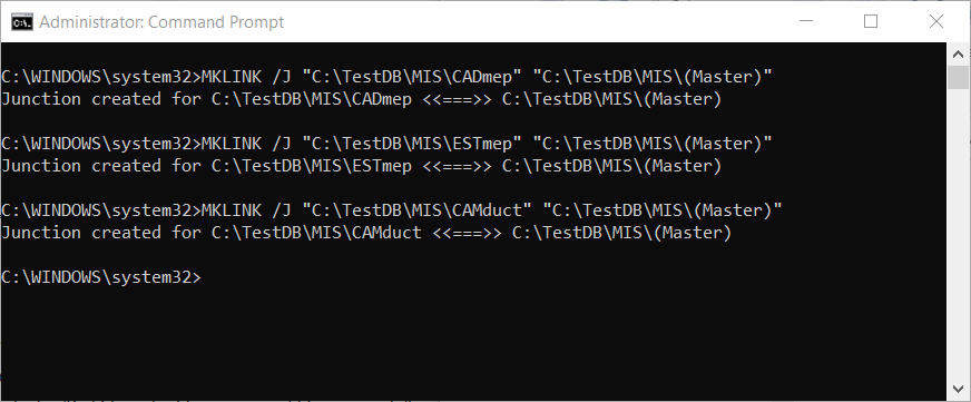
To create a Junction you need to open a Command Prompt with Administrative permissions. One that’s done, you use the MKLINK command to make a Junction Link to a Junction Target. The syntax looks something like this….
MKLINK /J "link folder" "target folder"
Here’s a screencap of my DOS Command Window where I make Junction Links to the (Master) reports folder…
When done (if Successful) you’ll see those product specific folders again for CADmep, ESTmep and CAMduct. But this time, you’ll notice the icons are slightly different and look like a shortcut icon even though the folder acts like a regular folder.
Here you can see a side by side recording of the process happening in real time…
Step 5: Use Fabrication As Normal
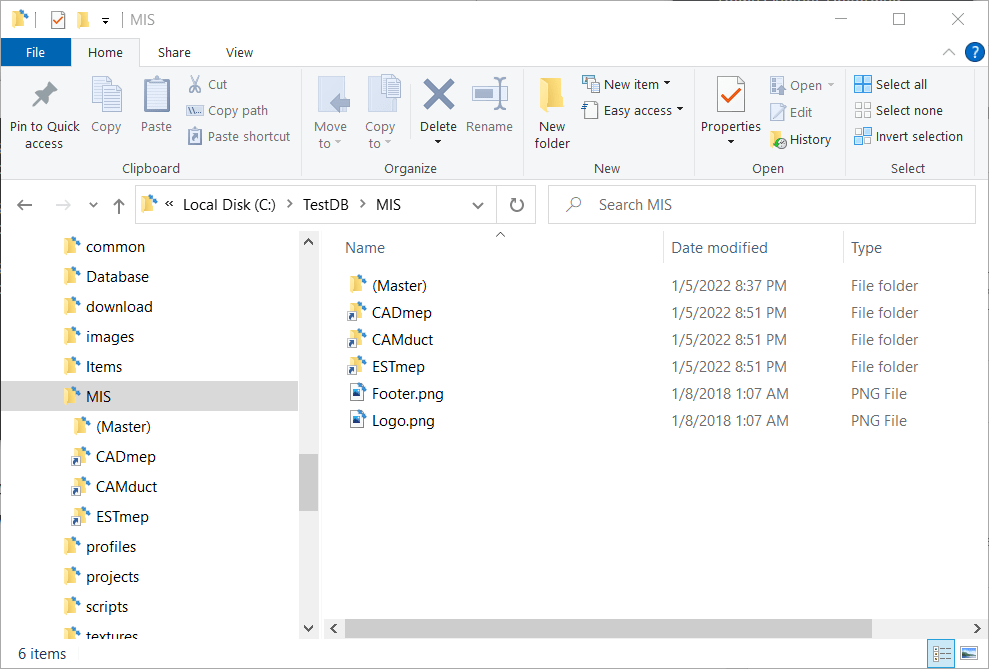
Once you have the junctions created, you can use your products as normal. Each fabrication product looks to the folder specific to it, which Windows redirects to the file in the (Master) folder.
One thing to note, is that when browsing the (Master) and product specific folders, the only clue that these are Junction Links is the Shortcut looking arrow on the icon. If you don’t know what’s going on, it would appear that you have 4 folders each with the same files. But if you try to delete the files in one, they will indeed disappear from the other folders too. After all, these folders are Links back to the Target.
Here’s a recording of all 4 folders show at the same time. You’ll see that changes to any one also happen to the others. You may need to Refresh the views to see the changes but they indeed are seen from the Target and all Junction Links. This means that while there’s 4 folders showing the same files, they only take up the size on disk in one folder.
Summary
Junction Links work well for letting all (or some) of your Fabrication products use the same list of Reports. But there are a few noteworthy items to be aware of….
Junctions Links and Point to Targets on a different DRIVE or FOLDER as long as it’s on the SAME machine. You can’t make a link to a target from a computer to a server for example.
If you access your database from a network location, you need to make make the links from the server so your IT Department may need to get involved. Your local software when accessing the server share will honor the junctions it sees on the server.
If you don’t know what’s going on or look closely, it appears you have duplicate data. Make sure you don’t delete things from one folder thinking they’ll still be in the others.
If you want to undo this setup, you should delete the Junction Links FIRST just like any other folder before deleting the Target folder. If you delete the Target first, the you’ll have trouble deleting the links.
IF you Sync your database from a master source location like Dropbox or using a utility like Robocopy, the Junctions are NOT copied, but are instead copied like regular folders. There may be some special utilities that copy the junctions but I’ve not found them. So what is 4 views of 1 copy of a file on a network, when synced to your local system becomes 4 copies of the files in 4 folders. For the most part, it’s not an issue as you manage from the master source location. None the less, this nuance is worth mentioning. Most Sync utilities do NOT recognize the special nature of a junction and treat them just like a folder.
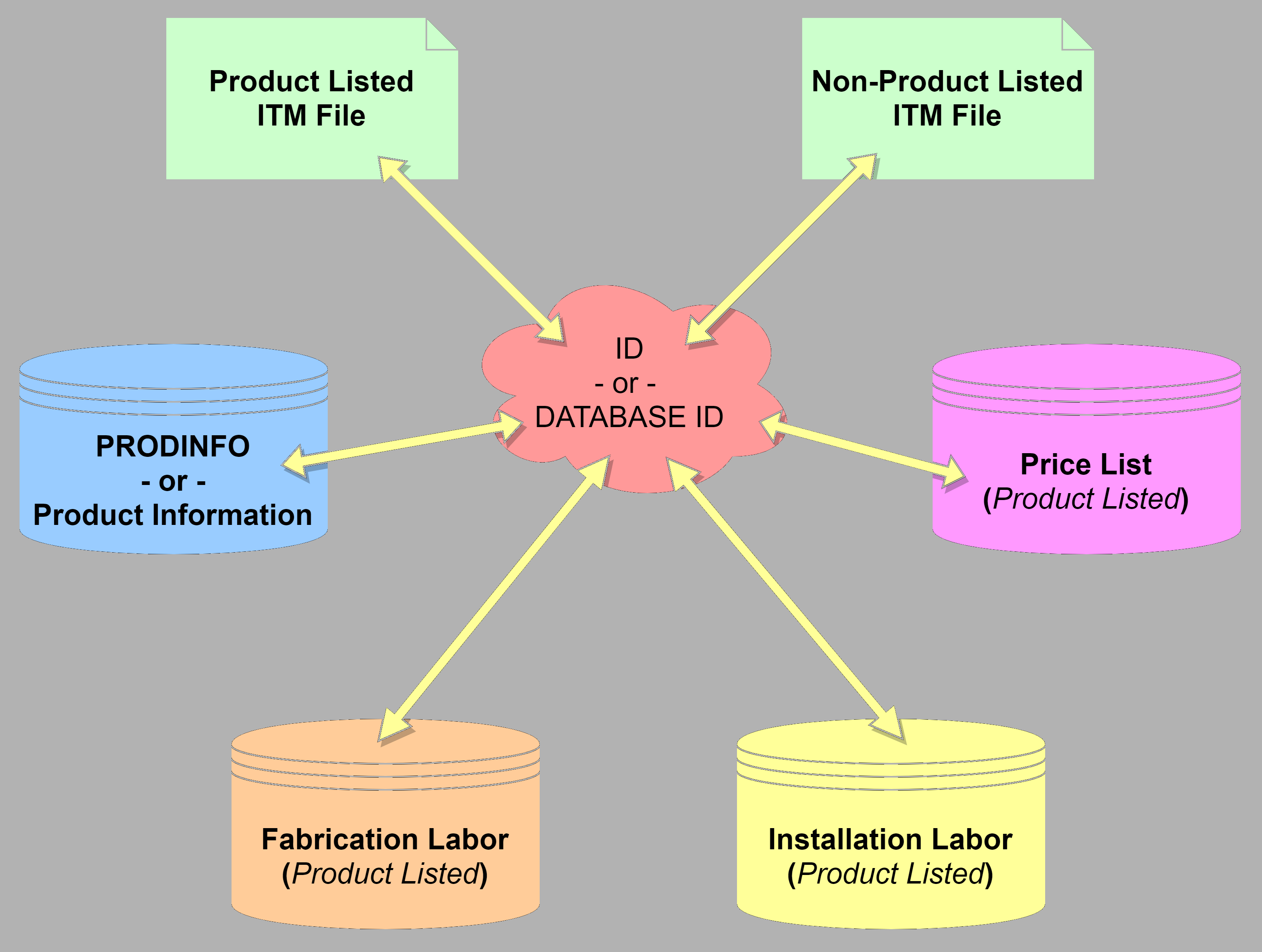
I have a lot of people ask how Pricing, Laborand Product Information (ProdInfo) works in Autodesk Fabrication. It’s a simple concept once you understand it. But it’s also rarely illustrated graphically so I’ll attempt a more graphical explanation here.
At it’s core Product Information requires the use of an ID, sometimes referred to as a Database ID. Pricing and Labor can be handled two separate ways depending how you need to price and labor your items. One of those ways is using Product ListedPricing and/or Labor. When using Product Listed Prices or Labor, you also use an ID.
Generally speaking, 100% of your parts should have and ID. ID’s should also be unique without a very good reason for duplication. There are a couple good reasons to duplicate ID’s across content but we won’t get into that here. If this article is helpful to you, those reasons would only serve to complicate the issue at this point.
Product Information & Product Listed Prices & Labor
When you have an IDassociated with your ITM content, that ID serves as the “Glue” to tie together all the other database tables in Autodesk Fabrication. An ITM with an ID, looks up that ID in the Product Informationdatabase to find the related product information. IT also does the same for Pricing, Fabrication Labor and Installation Labor.
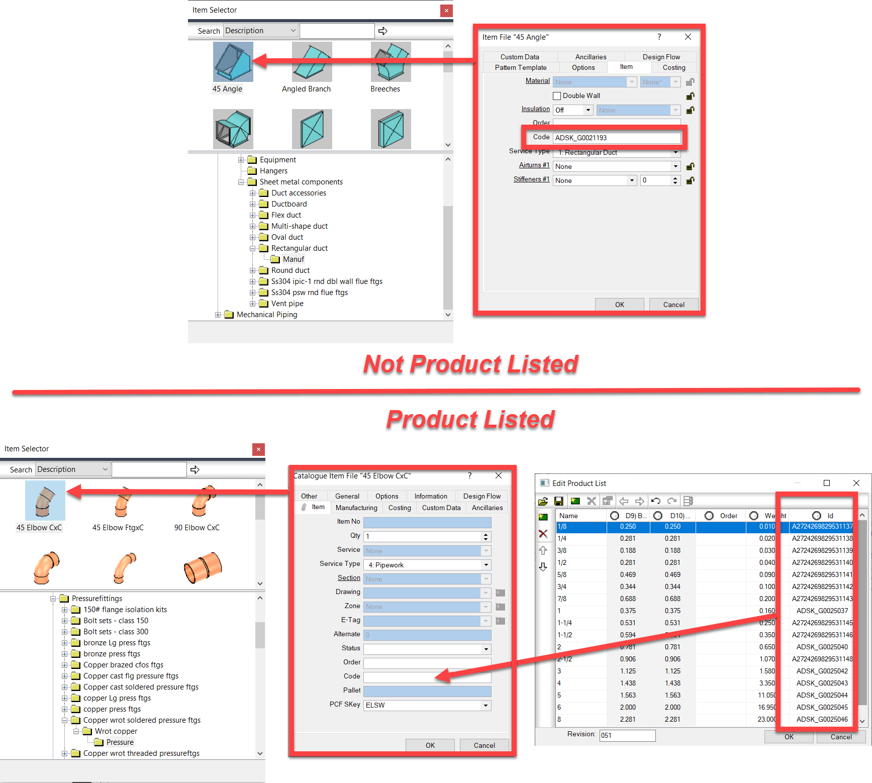
The following images shows where the ID is stored in your ITM Content. For ITM’s which are NOT Product Listed, you simply type the ID into the “Code” field from the Properties window.
For Product Listed ITM’s, it’s handled slightly different. You add the ID column to the Product List and add the ID’s there. When you add a product listed ITM to your model or takeoff, the value of the ID for the size you select gets automatically placed in the “Code” property. When that ITM is merely sitting in your library on disk, the value here doesn’t matter. It can be blank or any one of the ones in the Product List. Adding the ITM to your model then updates it to the proper ID.
Product Information
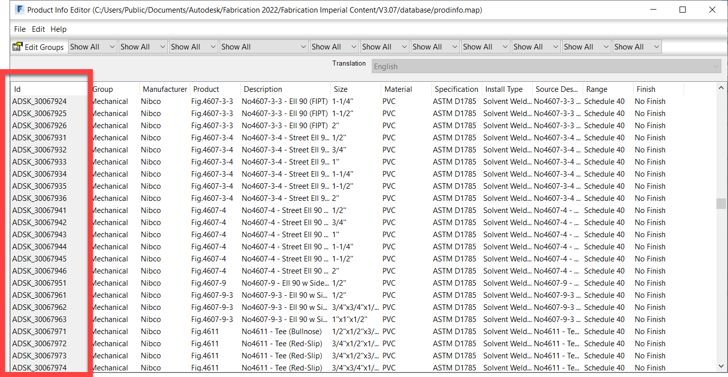
Product Information or ProdInfo for short lists additional data about the fitting or item. The following image shows the related data in ProdInfo with the ID column outlined.
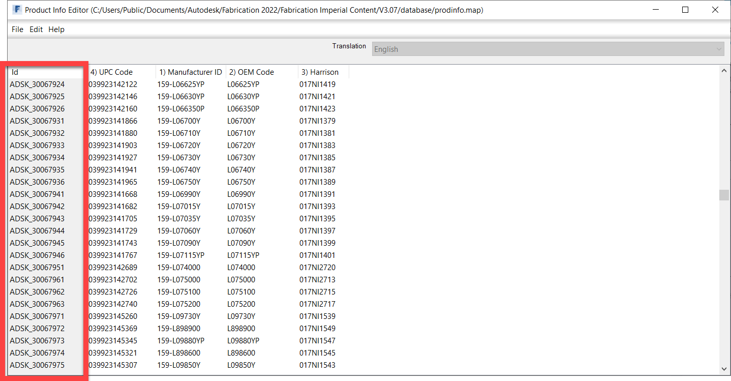
In addition to standard product information, you can also change to a Supplier view of ProdInfo where you can add additional columns for any other types of data or numbers you want to track. The following image shows some added data fields like UPC Code and Harrison HPH codes.
Pricing
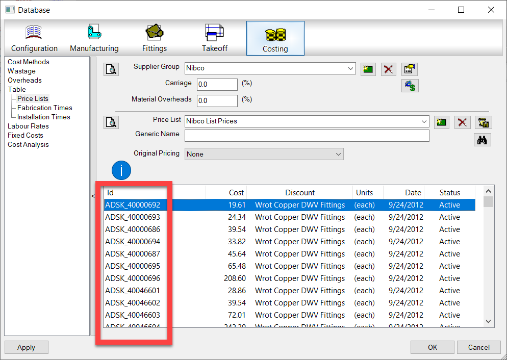
The following image shows a Product ListedPricing Table. The ID is outlined. Here’s where you can add pricing information to the ID of the ITM. Note, the term Product Listed Price here is a little confusing because “Product Listed” prices can apply to non-product listed ITM’s. While an ITM may not contain a “Product List“, the pricing table is still a “List of Products” that are referenced by ID.
Labor (Fabrication & Installation)
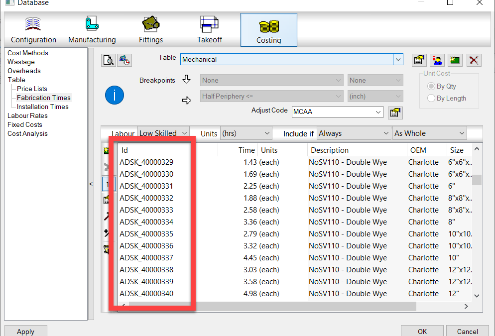
In the same way Price List’s work, Fabrication and Installation Labor work in a similar way. Product Listed labor can apply to any ITM, Product Listed or not as long as it has an ID. The following image shows Fabrication labor but Installation Labor works identically.
Breakpoint Pricing & Labor
A second way to specify Price and Labor doesn’t require ID’s because they’re not looked up from a list. These would be Breakpoint Price and Labor tables. With this type of Price or Labor table, you build a 1d or 2d Breakpoint Table that uses the part’s size as a guide to look up the proper price or labor rate in a matrix.
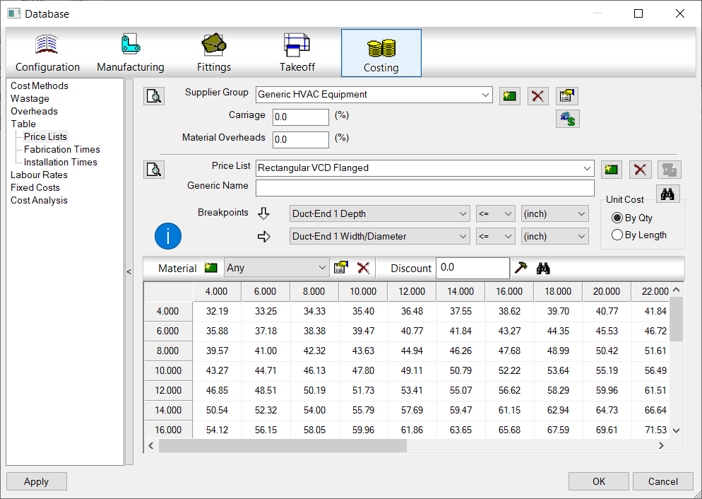
Price Breakpoint
The following image shows a Pricing Breakpoint table. You can make more than one breakpoint grid and have each apply to a different material if you have the need.
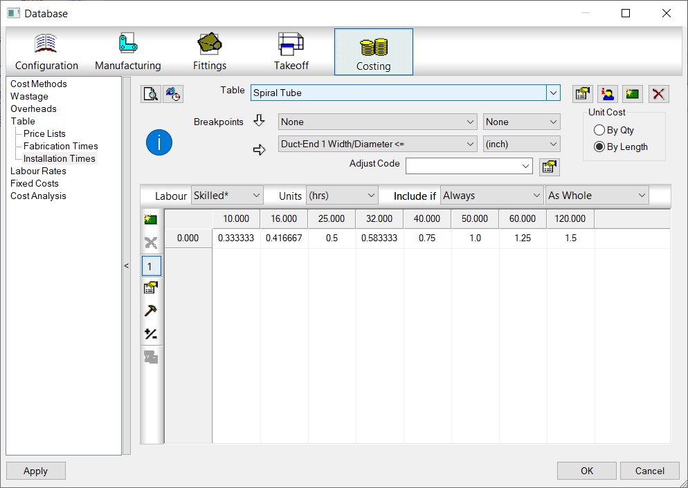
Labor (Fabrication & Installation) Breakpoint
Similar to a Price Breakpoint, you can make a matrix for Labor as well. With LaborBreakpoints, you can also make more than one matrix and have it apply to various properties of the item labor is being applied to like Insulated or Non-Insulated.
Finding the Right Price & Labor Tables
While all you need for ProdInfo is an ID on an ITM and matching ID entry in the ProdInfo Database, Price and Labor need an extra step.
Price and Labor can have multiple tables to help you organize the values or even manage the price for the same item from multiple suppliers. To handle this, you set the tables in the ITM properties. This is true for both Product Listed ITM’s as well as Non-Product Listed ITM’s.
Setting these tables tells Fabrication which table to look in to find either the ID or the Breakpoint table which uses size and property criteria to apply to the ITM.
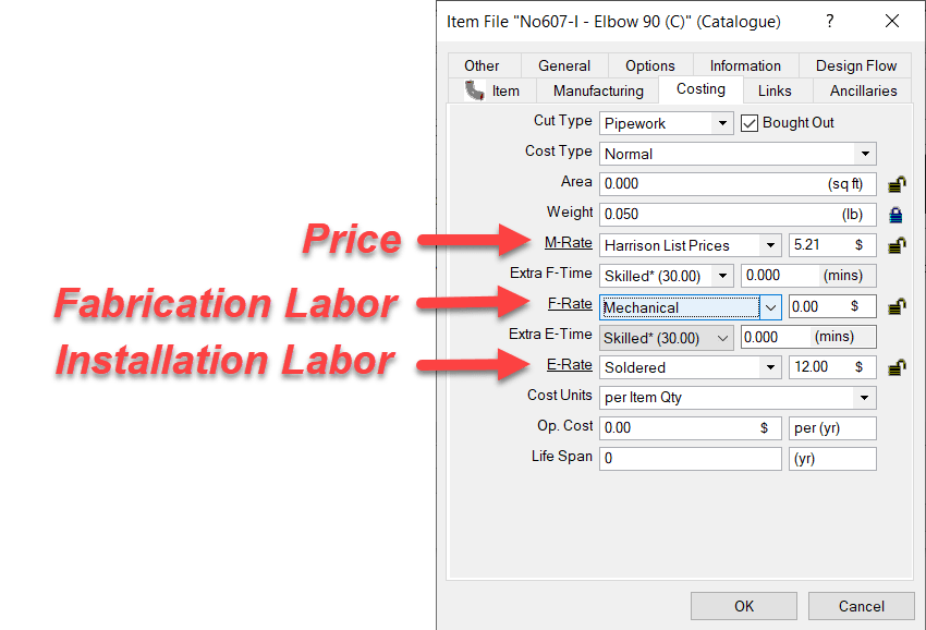
The following image shows where those tables are configured in the Costing tab of the ITM properties.
M-Rate is were the Price of the material comes from. This is set typically for bought items where you pay a set price. If you leave this set to “None“, material pricing would be calculated on a “Price per Pound” formula based on the material weight. This is typically done for Fabricated Sheetmetal fittings where the weight of the Sheetmetal is calculated based on area and gauge and then priced per pound. For piping or bought items, this table would typically point to a table that contains the pricing.
F-Rate is where you select the Fabrication Table to use to look up the Breakpoint Table or ID if Product listed labor. This is most commonly set to “None” for Piping items or other bought items where you just buy them but don’t fabricate them. It’s usually set to a specific table for Sheetmetal fittings which you fabricate and want to calculate fabrication labor.
E-Rate – This table is for Installation Labor. The “E” in “E-Rate” stands for “Erection” if that helps you remember. This will be set for most contractors who are installing duct or piping. It would typically be set to “None” if you were a fabricator only selling to others who install.
Summary
Hopefully this helps give you an idea how pricing, labor and product information functions (at a high level) in Autodesk Fabrication. There’s a lot more strategy and nuance you can get into but this is a good place to start understanding the basics of how it all works.
Seems obvious once you see it but sometimes the easy things are the most ellusive.
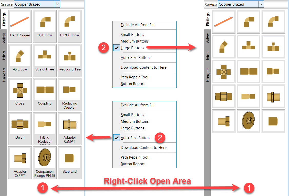
If you’re noticed descriptions on some of your computer’s fabrication palettes and not others, it’s likely the “AutoSize” option you’re looking for.
Right-Click on an open area of the service palette and select the option you prefer. This applies to CADmep, CAMduct and ESTmep. Revit…not so much. Revit likes to do it’s own thing.
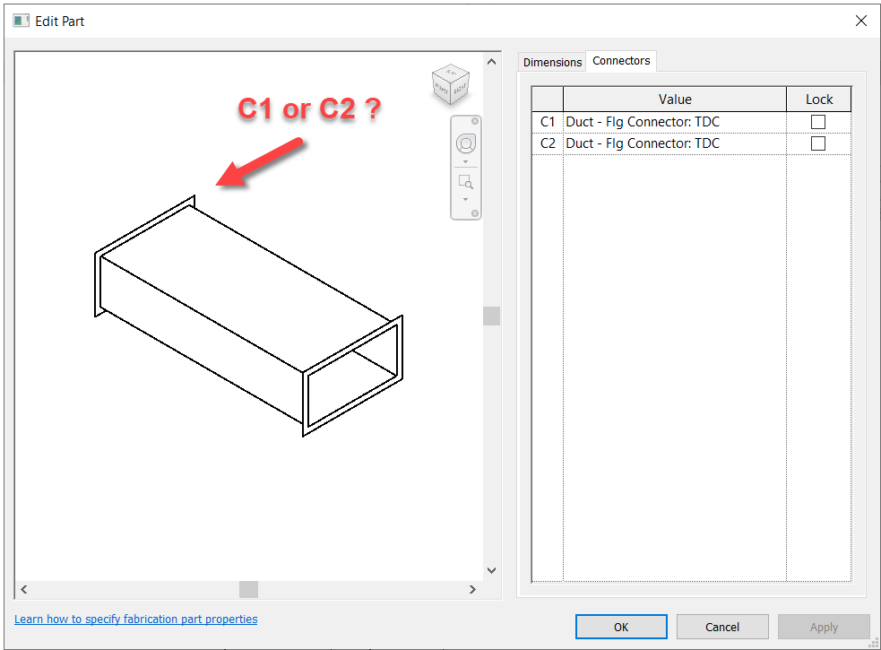
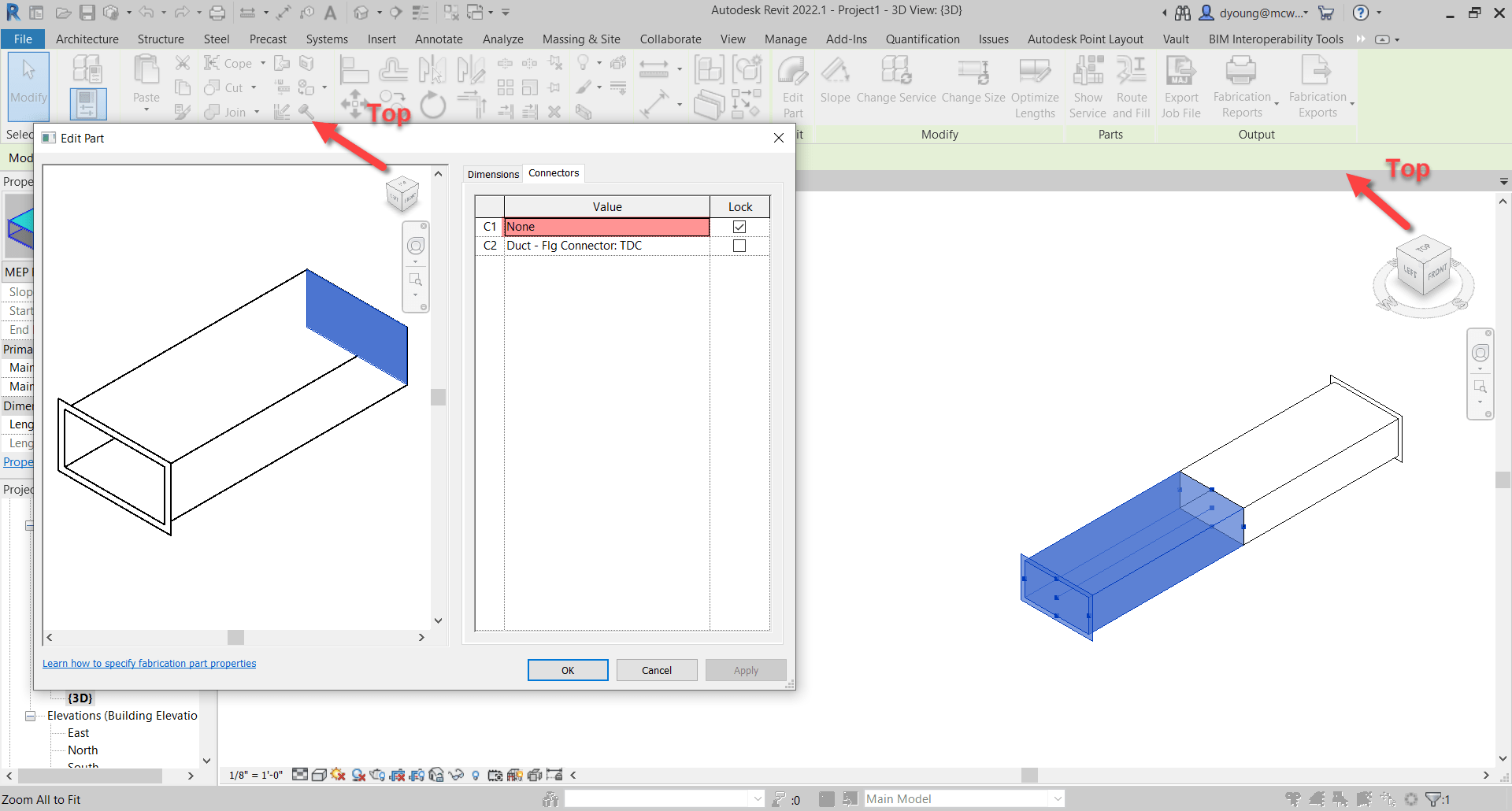
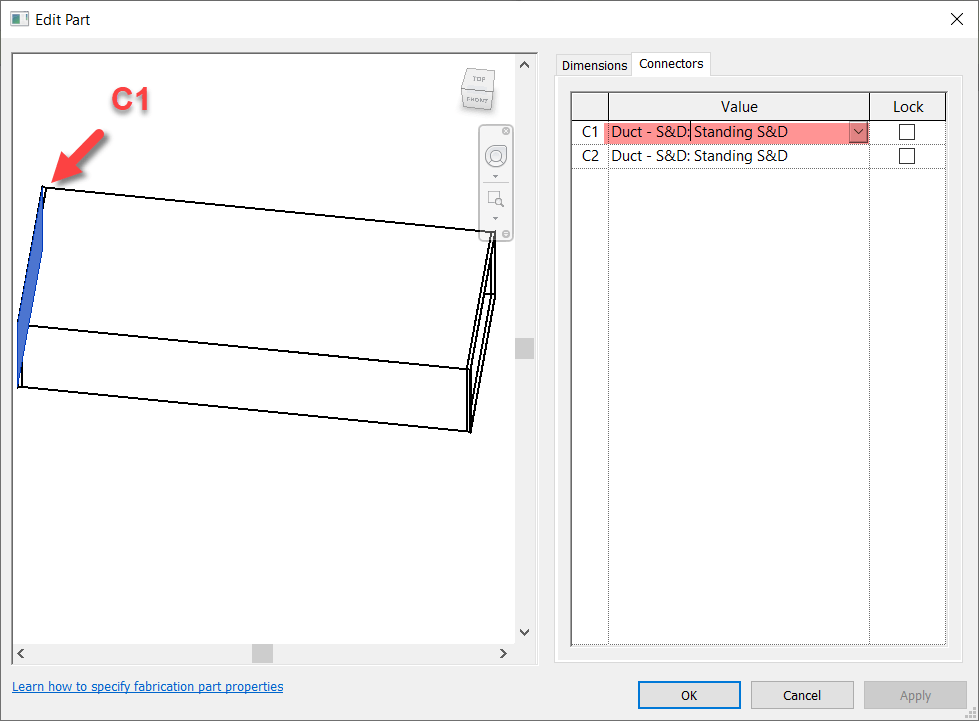
Fabrication Parts in Revit allow you to edit their connectors just like in CADmep. However, unlike CADmep, you can’t simply hover over a connector to determine if it’s C1 or C2.
So if you need to change a connector, you’re essentially guessing which one to change. Trial and error is at best 50% unless you’re lucky.
So how can you improve this “guessing” based workflow?
Thankfully I have a great network of people smarter than myself. I often get the credit for sharing the information but really, the credit belongs to those who show me. In this case, two of my industry friends showed me ways to improve the odds.
Method 1 – Slope
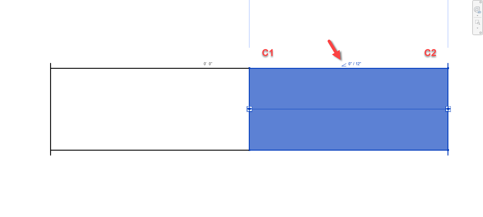
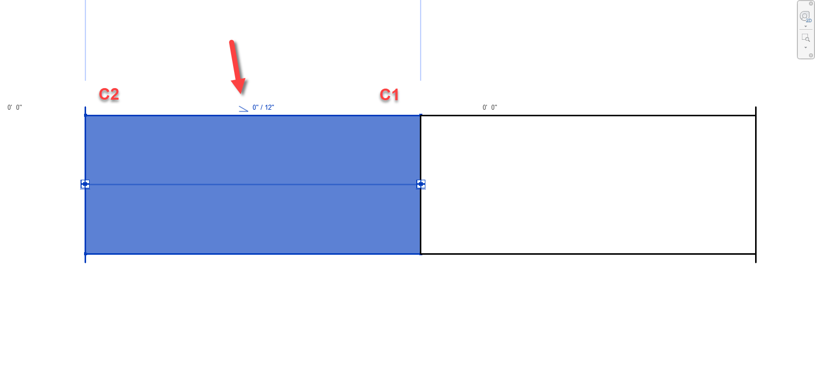
For this first method, credit goes to Liz Fong from MacDonald Miller. When you place a piece of straight pipe or duct, when you select it you’ll see a Slope indicator (< or >). This by default points to the C1 connector.
Duct/Pipe placed defaults the Slope symbol pointing to C1
Duct/Pipe mirrored also defaults the Slope symbol pointing to C1
There’s a couple downsides to this approach that may apply in some scenarios….
This doesn’t work for fittings. Only Straight Pipe/Duct.
If you click the Slope Symbol, it changes direction and is no longer accurate.
This should really only affect Plumbing or sloped Grease Duct systems. Otherwise there’s not a lot of reason to change direction on a non-sloped system.
Symbol could still be accidentally clicked and reversed anyway and then be wrong.
Once changed, Slope symbol direction is remembered and there’s no good way to “reset” it.
Still, despite the downsides of this approach, I’m going to go out on a limb and suggest that even on a plumbing system, less that 50% of the slope symbols will be changed from their default. This alone makes this method better than a 50/50 guess like before.
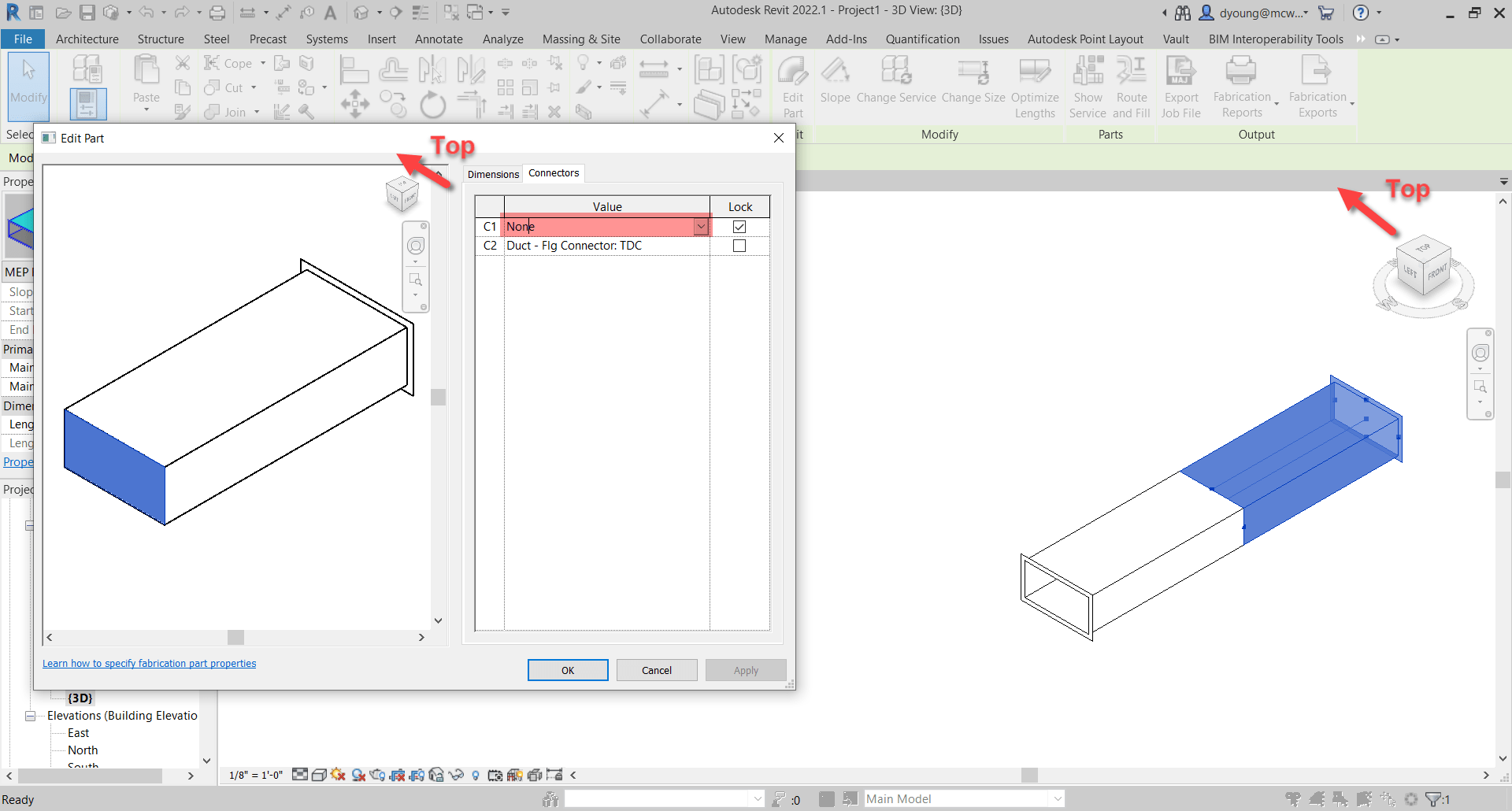
Method 2 – View Cube/Viewing Direction
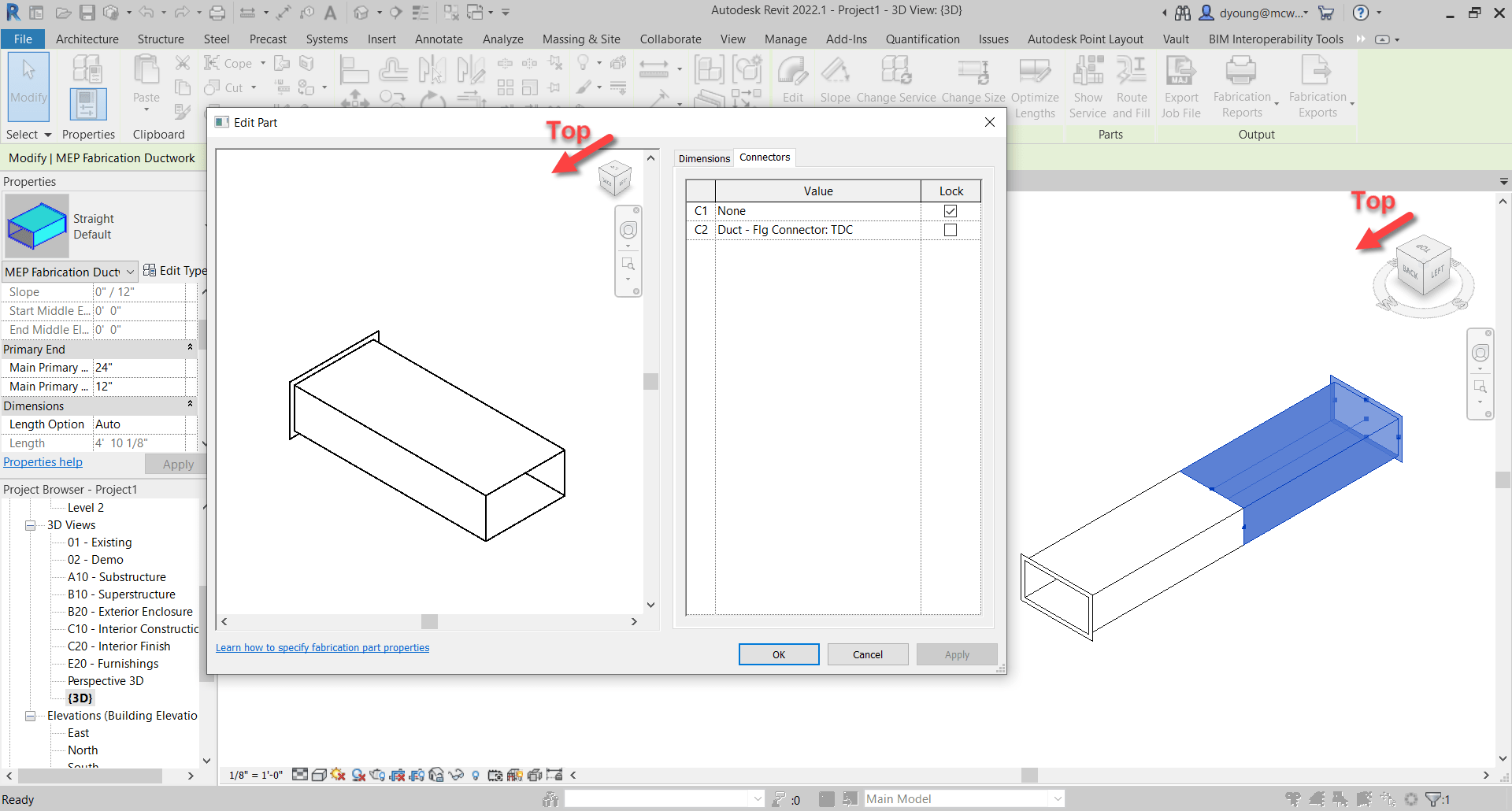
This next method takes slightly more work, but is almost 100% accurate. Credit for this method goes to Alina Y. from JH Kelly.
In short, from a 3d view, if you make sure the View Cube in the Part Editor window is aligned to the Revit View you’re in, the fittings is oriented in the same direction in the editor as in Revit. You can then select the connector in the Part Editor window and it highlights the connector end associated with it.
Duct/Pipe placed in Revit matches the editor when View Cubes are aligned. Selected Connector highlights.
Duct/Pipe mirrored in Revit matches the editor when View Cubes are aligned. Selected Connector highlights.
This method is almost fool proof and has a few benefits over the sloped method we showed earlier.
Works on Fittings in addition to Straight Duct/Pipe.
Slope direction doesn’t matter.
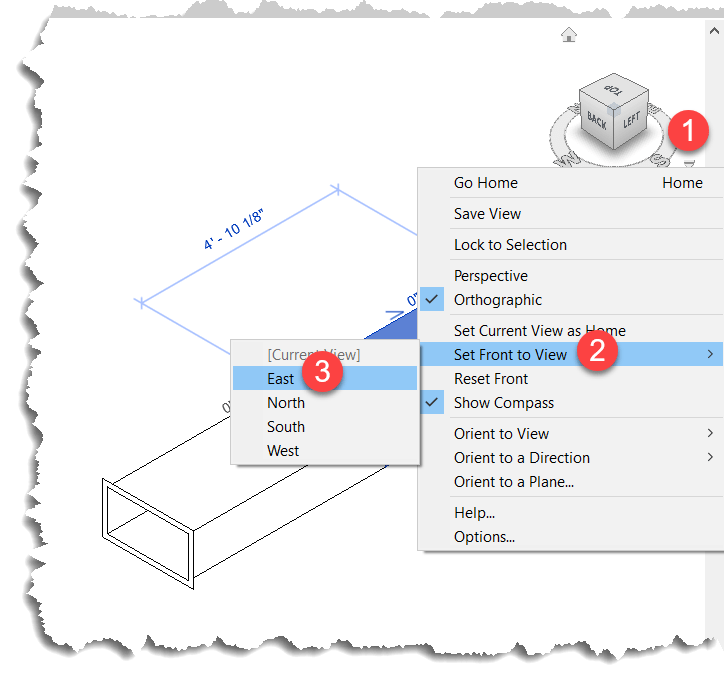
But we did say Almost. Where this method fails, is if the View in Revit is redefined.
When you set a new Front View, the view in Revit no longer matches the orientation in the Part Editor window as seen in the following image…
Luckily, this is easily remedied by simply resetting the Front View in Revit.
This method also works in Plan and Elevation Views with a slight twist. There’s no View Cube in the Revit window so it’s up to you to understand which viewing angle Revit is in. Next, you can make the View in the Item Editor match but when you look at a connector straight at the edge, you don’t see it highlight. You can then hold the SHIFT key and use the Middle-Mouse Button to slightly rotate the view so that you can see the connector that’s highlighted.
Here you can see what that looks like…
Summary
While not as quick and efficient as hovering over a connector in CADmep, either of these methods or even used in combination can increase your odds of changing the Correct connector on the first try.
While method #2 is more fool proof than method #1, there’s a reason I explain both and here’s how I’d use them both.
For non-sloped systems, the chances the slope symbol is reversed is very low. Because you’re likely selecting the part anyway to edit a connector, a quick glance is all you need to know which connector to change. Quick and easy for straight part on non-sloped fittings. No fuss. No muss. In this scenario, Method #1 is super quick.
For fittings and sloped systems, I would then shift to Method #2. Take a little more time, but it’s certainly quicker than being wrong 1/2 the time and then undoing the connector you just changed and then changing the other. That “trial and error” method results in 3 connector changes when you guess wrong. This is where Method #2 really shines…you get it right every time. If you’re Front View happens to be redefined, it’s easily rest.
Thanks again to Liz Fong (MacDonald-Miller) and Alina Y (JH Kelly) for their great input in coming up with these methods. They’re two of my favorite “Go To” people when I get stumped or need a little help orienting my thoughts.
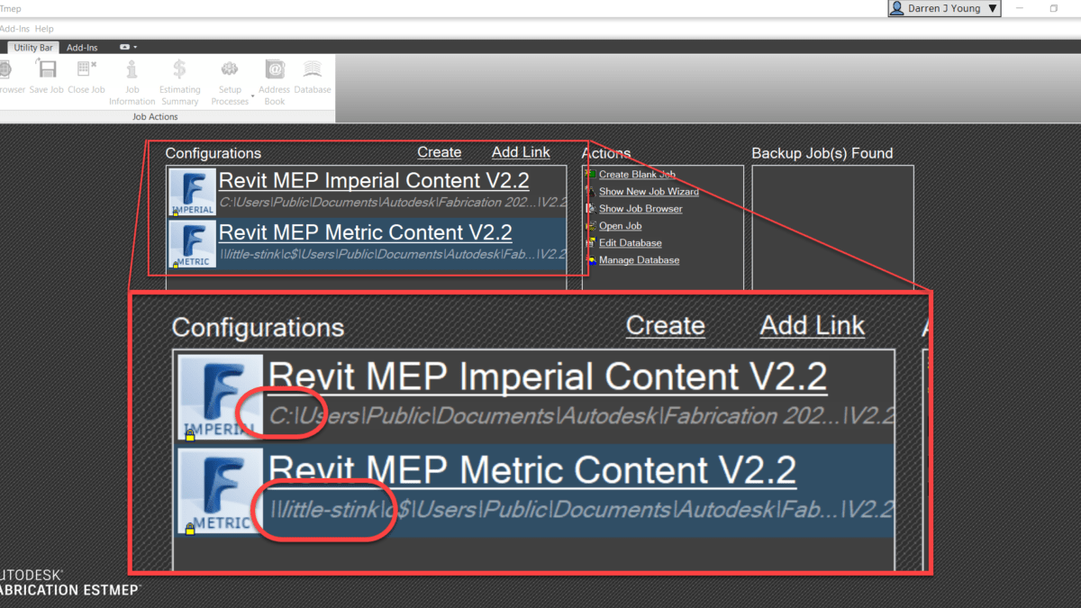
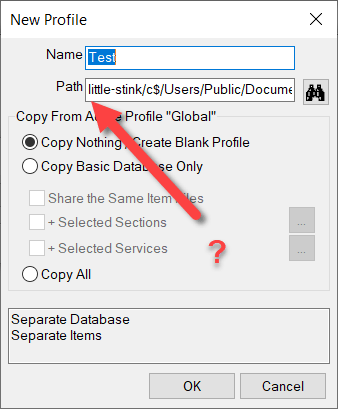
If you use UNC pathing to get to your Autodesk Fabrication Database, you might find issues when trying to create Profiles if you use them. UNC pathing or (Universal Naming Convention) is where you specify a server and share vs a drive letter. You can see below, the Metric Autodesk Fabrication Configurations is using a UNC path…
When using this configuration, you can create a profile from the File drop down menu in ESTmep and CAMduct or by typing MAPPROFILES in CADmep.
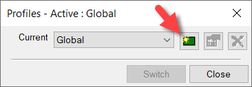
Creating New Profiles
You go to create a new profile by clicking the Green button.
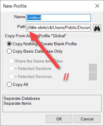
From here, the New Profile dialog starts with the default name “Untitled”. Notice also, the double leading forward slashes before the server name in the UNC path. (Yes, ‘little-stink’ is the server name)
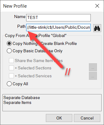
When you start to type a profile name, the leading forward slashes get stripped. This is likely a bug. You can see that in the following image…
If you click the OK you’ll get an error that the profile can’t create the required folder.
However, the fix is easy. If you just add the leading forward slashes again, you” be able to create the profile.
It may be easier to see from a video. You can watch the process here…
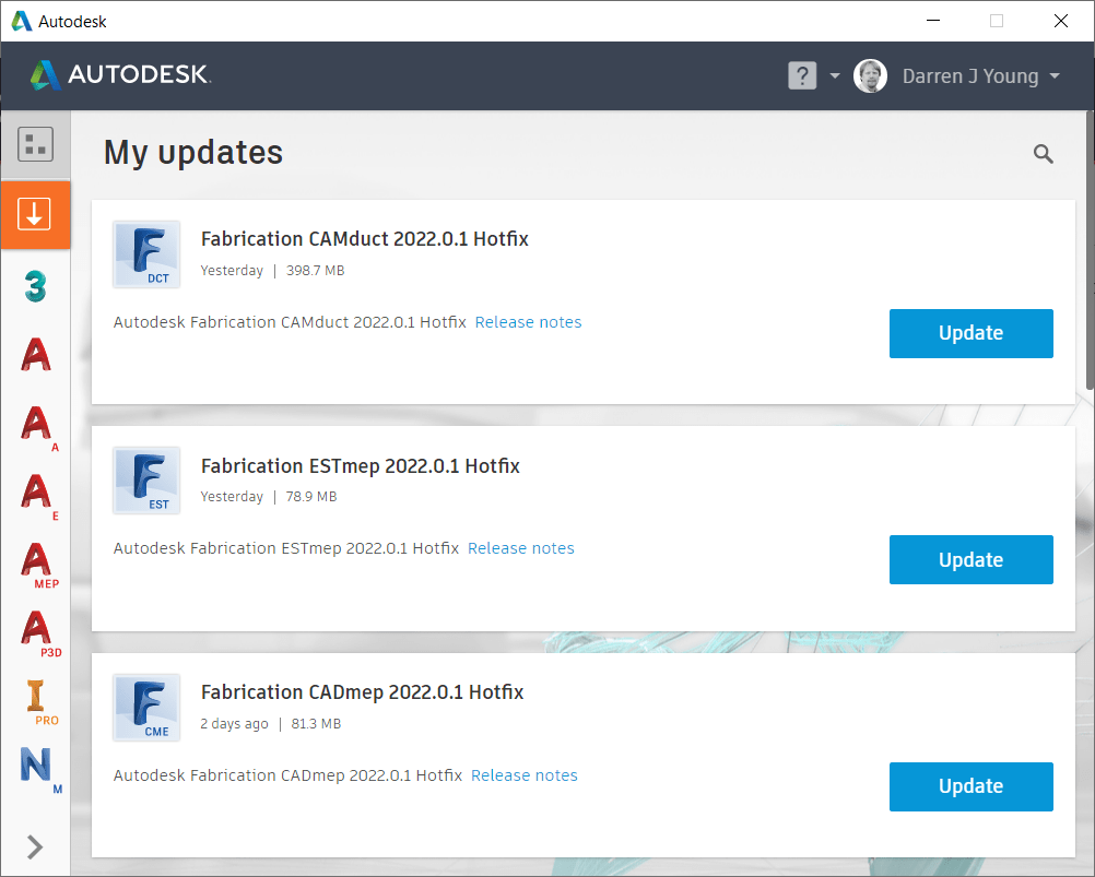
It’s recommended NOT to install this update for CAMduct or ESTmep. Installing the 2022.0.1 Update will prevent access to the Projects folder. CADmep does not appear to have issues with this update.
It’s been a long time, but Autodesk finally released an update to Autodesk Fabrication. 2022.0.1 Update was released recently and contains several fixes for 2022 versions of CADmep, CAMduct and ESTmep.
Install from the Autodesk Desktop App or download from your Autodesk Account portal (https://manage.autodesk.com)
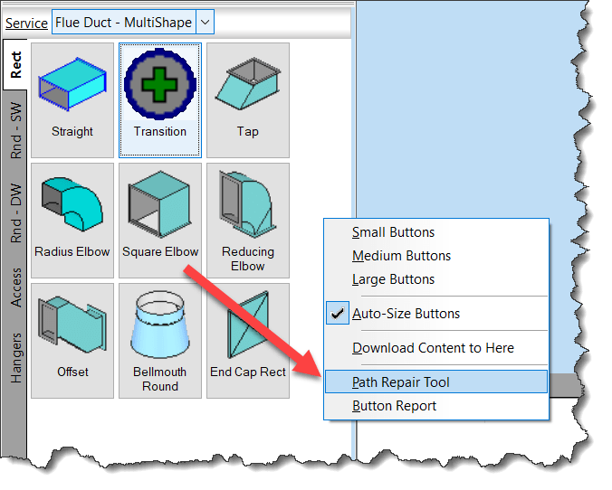
Your services should not have broken links to ITM’s. Not only is it sloppy database management, it can slow performance of your database.
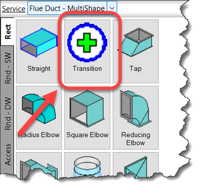
Use the Path Repair Tool to find (and fix) broken links in your services.
Right-Click and empty area of your Service Palette and select Path Repair Tool.
When you run the Path Repair Tool you’ll be asked to select a mapping file. You can click cancel and the tool will continue on. When it’s done, you’ll have a list of broken paths copied to the Windows Clipboard that you can paste into a file.
From this file, you can then create a mapping file. The mapping file is merely a text file in the format….
OLD PATH/NAME,NEW PATH/NAME
So the data you paste from the clipboard is good starting point, it lists all the broken paths. There may be duplicate paths listed if the path is used in multiple service templates. It’s ok to remove the duplicates.
Simply ass a comma after the broken path name and enter the new, corrected path. Once done, you can save the file and use it when you run Path Repair Tool again. It’ll then go and fix all those broken paths.
NOTE: This repair technique does NOT work if you have commas in your folder or file names. (See Best Practice #11)
If you’ve not downloaded the Autodesk Fabrication Script Libraries lately, you might want to grab an updated copy. There’s been several updates over the last month. Here’s what’s changed…
DamperRotation Property (undocumented) has been added to all Debug, Job and Library scripts. Support for this property was added in 2017 but never documented. It’s there to support the rotation of Dampers on Fabrication Parts in Revit. It should be noted, that this value is Added to the Angle property of the assigned damper. As such, it acts as an Adjust and not an Override. e.g. Damper w/Angle of 90 + Rotation Property in the ITM of 90 results in a damper rotated 180 degrees.
StiffenerGroup Property added to the Autodesk Fabrication 2022.0 and later versions of the Debug, Job and Library scripts.
AirturnGroup Property added to the Autodesk Fabrication 2022.0 and later versions of the Debug, Job and Library scripts.
SplitterGroup Property added to the Autodesk Fabrication 2022.0 and later versions of the Debug, Job and Library scripts.
InsulationStatusLock Property added but listed as “Unavailable” as it stopped working in 2017. Added in the hopes it gets fixed in future versions.
StructureType Property added to the Autodesk Fabrication 2022.0 and later versions of the Debug, Job and Library scripts. Property was “Write Only” in 2021 and prior versions so was unable to display in prior versions.
Product ListHasCustomData Property has been added to all Debug, Job and Library scripts.
Product ListHasFlow Property has been added to all Debug, Job and Library scripts.
ItemPCFSKey Property has been added to all Debug, Job and Library scripts.
ItemCostByLength Property removed from Material Debug scripts (never really belonged there).
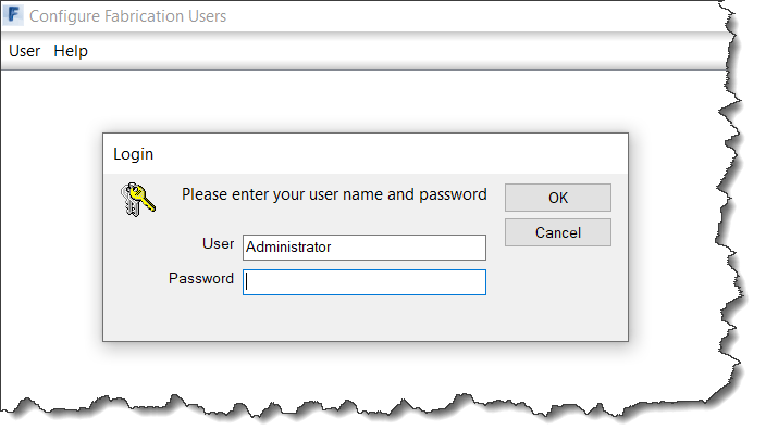
If you run Autodesk Fabrication as a multi-user installation, there’s a defect in the Configure Users utility. When you run the utility from a 2022 installation, it won’t read any of the user accounts you have configured.
In fact, the only way to login, is to use the Default Administrator account Autodesk uses if there are no users configured. It won’t read your Administrative account regardless of what the login is. To see the issue, you can use the following to login and see the problem…
User Name:AdministratorPassword:Admin
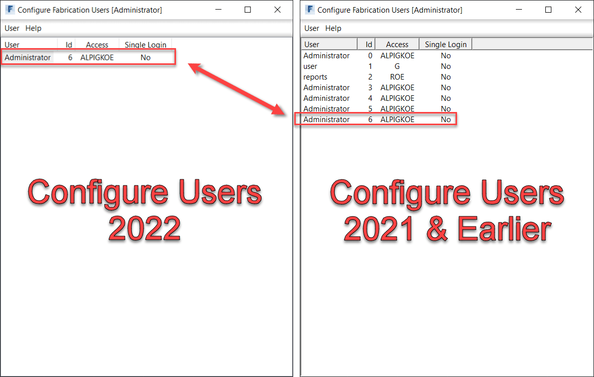
Once logged in, there will be one account. You can make more but when you exit and come back in, those accounts don’t show up. IN fact, even the original Administrator account isn’t there, it’ll make a new one. The following image shoes the users accounts that were created in 2022 be repeatedly going into it. Next to it is the 2021 utility showing those same accounts. As you can see, they are there, its just 2022 won’t show them.
Note that all the other Fabrication products will read/honor the accounts properly. It only seems to be the Configure Users utility that had the issue.
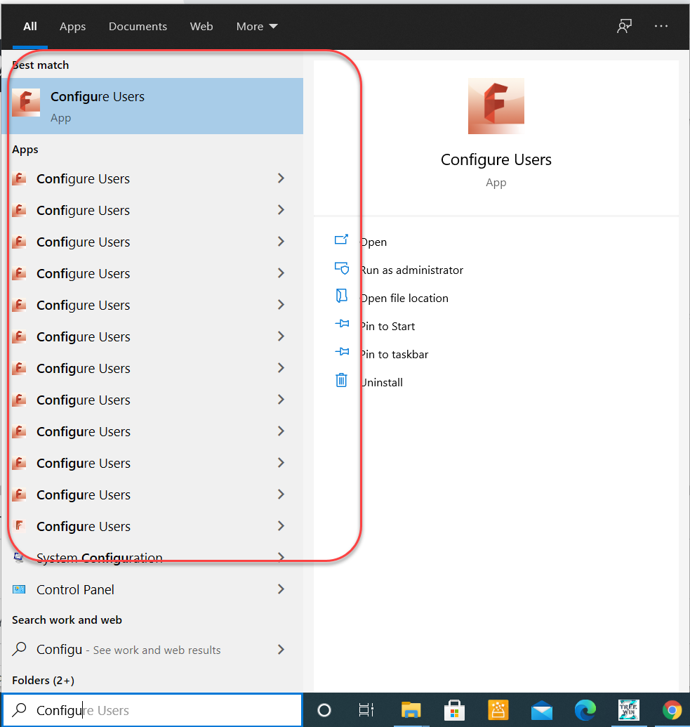
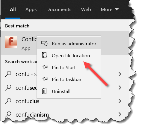
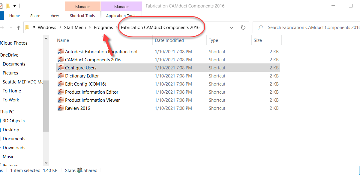
How to Determine Which Version of Configure Users To Run
To make things ‘easy’, Autodesk chose not to add the version in the name of the shortcut. Simply looking for ‘Configure Users‘ shows a lot of indeterminate results.
To pick a particular version, Right-Click on one of the shortcuts and select ‘Open file location‘.
This will display a File Explorer window to the location of the shortcut you selected. As you can see below, the one I happened to pick was for CAMduct Components 2016. The product doesn’t matter, only the version, You can navigate back a folder then pick one of the Fabrication products for any version you want. 2021 and earlier will work.
Not sure if or when they’ll get around to fixing this. While 2022 has had a few issues fixed, they didn’t release any updates (yet) for 2021. Regardless if they fix it or not, it’s easy to work around by using any other version.