Configuring Fabrication Configurations

When you manually add a Fabrication Configuration to your system yourself, it only works for the currently logged in user. In fact, you may have noticed this with your own configurations compared to the default ones Autodesk adds during installation. You can see the difference by the presence of a little Yellow Lock icon in the lower left of the Configuration’s image.

So when you use the Add Link option to add a configuration, it’ll only exist for you. If someone else logs into the computer, the configuration won’t be displayed for the new user. Autodesk’s on the other hand…will still be there.

The difference between these two ways Configurations work is based on how the configurations are “configured” in the Windows Registry. So let’s take a look by starting the Registry Editor.

The first thing to know, is that there’s two ways to start the Registry. Just running the REGEDIT command opens the editor and displays everything. The other way is to Run as Administrator. When just run, you’ll have read/write access to the HKEY_CURRENT_USER branch (‘Hive’ is the proper term) often abbreviated as HKCU. This is the branch where the User configurations are stored.

The Computer based Configurations (like Autodesk’s) are stored in the HKEY_LOCAL_MACHINE branch often abbreviated as HKLM. When you run REGEDIT normally, you’ll see the HKLM branch but it’s Read-Only. To write to the HKLM branch, you’ll need to launch REGEDIT with the Run as Administrator option. Your IT Department may restrict this from you so you may need to involve them if you want to implement Computer based Fabrication Configurations.

The other thing to note, is that when you Run as Administrator, the HKCU branch is there but the settings may be missing or different. This is because, the Registry Editor is technically running as another user and that branch is User specific. You can see the two branches I’ve referenced in the following image.


Converting Configurations to ‘Computer’ Based

While you can edit the Registry manually, the easiest way to convert your Fabrication Configurations to be Computer based (not User) is to run the Registry Editor normally (not as Administrator) and export the HKEY_CURRENT_USER settings. The settings are in the key…

HKEY_LOCAL_MACHINE\SOFTWARE\Autodesk\Fabrication <year>\Configuration

The <year> represents the version year of Autodesk Fabrication (CADmep, ESTmep, CAMduct, Remote Entry, etc.) or Revit. You can see that in the following image. If the Configuration key isn’t there, that means there’s no configurations “configured” for that version year. If a specific “year” isn’t listed, it means that version wasn’t installed.

Once you get to the Configuration Key, you can export it using the File -> Export option as shown here…

While you can Export a single configuration, I like to pick the Configuration Key and do them all. We can get rid of what we don’t want later. The main point to note when exporting is to change the Save as type: to the Win9x/NT4 Registration Files (*.reg) option. This will save the export in ASCII text which you can edit in Notepad.

Once you export to a file, you can right click on the file and select Edit to open in Notepad. The following image shows how it looks and is marked up what I’ve removed vs added/edited. Note I also edited the Registry Hive from HKEY_CURRENT_USER to HKEY_LOCAL_MACHINE.

Once you’ve edited the file and saved it, you’re almost ready to import it. It’s generally not advisable to have the same configuration with the same name and same path in both the HKCU and HKLM branches.

So first, you can run REGEDIT normally and rename the Configuration folder…or just delete it (if you’re comfortable doing so). Then close the Registry Editor and run it again but Run as Administrator. You can now Import the file you just edited to import those new Registry settings. The following image shows what both branches might look like…

Now, when you launch Fabrication (CADmep, CAMduct, ESTmep, etc.) you’ll see the little Yellow Lock icon on your configurations. Revit won’t show that little icon but it does honor the ‘User’ vs ‘Computer’ configurations.


A Word About Fabrication ‘Profiles’

One side effect of ‘Computer’ or machine based Fabrication Configurations shows up if you use Profiles in your Fabrication Configuration. It doesn’t apply to Revit but does CADmep, CAMduct and ESTmep. When you use Profiles with ‘User’ based Configurations, the last active profile will be the default when you launch the program again. With ‘Computer’ or machine based profiles, you’ll always default back to the Global profile.

However this is easily fixed. To start, let’s look at the ‘User’ based configurations under HKCU when a profile was used…

You’ll see there’s now an ActiveProfile value in the configuration that wasn’t there before. That’s how Fabrication knows which profile to load by default. But also remember, the HKLM branch of the registry is normally Read-Only. So this means those programs can’t create this value when you change profiles.

The solution to this, is making those registry keys Read-Write in the HKLM registry branch. You can do that by running REGEDIT as an administrator like before and navigating to the proper registry keys. From here, you can Right-Click on the Key’s name and select Permissions….

You can do this on a specific configuration or at the root Configuration key and the permissions will be inherited by the downstream keys. Once the Permissions dialog shows up, select the User permission group and select the Allow toggle for Full Control. Again, you may need your IT’s help if you don’t have permissions to do this.

This will now allow CADmep, CAMduct and ESTmep to save the last Fabrication Profile to the Registry in the HKLM branch so when you start the software the next time, it’ll be able to use the last Profile used.

One good side effect of changing these permissions…you’ll now also be able to import or create more Fabrication Configurations in HKLM in the future WITHOUT having to Run as Administrator as you’ll now have Read-Write permissions to those keys by default.

Make sure if you do these steps, to do them for all versions of Fabrication. You can even make entries for versions you don’t have installed so they work later if you install that version. So if you want to prepare for 2025 versions, you can copy/paste/edit those registry settings in the file you exported and rename them as 2025 (or older versions) all in the same file, Being proactive in this way will minimize future support downtime.

Autodesk Fabrication: Connector Matching – The Feature Nobody Knows About & Why You Should Use It.

Do you know what ‘Connector Matching’ is as it relates to Autodesk Fabrication? It’s been in the product since the 2020 release. Yet most people I run into have no clue what it is.

There’s a good reason for that. It’s hidden from view. That is to say, there’s a good reason you don’ know about it. There’s no good reason it’s hidden from you besides Autodesk is pretty slopping (lazy?) when it comes to product design in recent years.


What is Connector Matching?

Connector Matching only works in Revit w/Fabrication Parts. If you’re not using Revit, you need not worry about it but setting it up won’t cause any issues either. It’s designed to place a matching connector on pipe after you cut in a fitting when modeling in Revit. CADmep, ESTmep and CAMduct will simply ignore the settings.

As an example, if you’re drawing a welded piping system and want to break it with a Grooved coupling, Connector Matching places the proper grooved connector on the end of the pipe when the Coupling is placed. This helps us build a system with Welded Pipe Spools that’s assembled in the field with Grooved Couplings…a very common activity in mechanical construction.

When Connector Matching isn’t configured, you’ll have issues cutting in things like a Grooved Coupling into a Pipe that’s part of a welded system.


Configuring Connector Matching

The reason many don’t know about connector matching is because it’s hidden. None of the 3 views (Manufacturing, Costing & Drawing) display this option.

To set Connector Matching, you Right-Click on a connector that’s configured for the Item you need to match. In this case, it’s a Victaulic 77 Coupling.

You can see the Matching Connector is set to “Same” by default. That’s certainly not what we need so select that menu option.

You can see now the Matching Connector is set to a Grooved Connector. So every time an Item with the “VIC_Coupling 77” connector is cut into a piece of pipe, the pipe will get a “VIC_Groove” connector.


Added Configuration to Make it Work

Above, you set the matching connector. Unfortunately, that’s not enough. There’s some added configuration to verify to ensure that it works.

One of the requirements of Connector Matching is to make sure the Pipe’s Connectors are NOT locked and defaulted to the connectors they should use. In other words, ‘Set’ but not ‘Locked’.

Here’s what your Pipe ITM most likely looks like…

What I recommend here is, Unlocking only 1 of the Connectors and Clicking OK. After you do that, go back and edit the ITM again and take a look at the Connectors.

You can see here that after Unlocking one of the Connectors and Clicking OK, going back to edit the ITM the Connector changed to “None”. This is a tell tale sign that there’s yet another thing you have to change to make it work.

In some Configurations, people have the Specification set to drive the Connectors. This is most commonly done for Sheetmetal but you see it in Piping as well. In the following image, the Piping Specification is configured to set the Connector to “None”.

What we need to do here is set the Connectors in the Breakpoints to “Not Used”. Note, if the Connector you unlocked earlier didn’t change to something other that what it was, you most likely don’t have this issue but still could…it could just be configured to use the Connector the ITM was set to.

You might have to hunt around for which settings apply. It could be on the ‘Any’ material or a specific material the ITM is using. The ‘Valid For’ could have it in ‘All Types’ or ‘Straights Only’. It’s possible too that you don’t have any breakpoints in the Specification at all. If that’s the case, then your Specification is likely already good. But if it’s not, simply ensure the Connectors are all set to “Not Used”.

Once your Specification is setup correctly (if it was a problem in the first place) you can go back to your ITM for the pipe and unlock both connectors but leave them set to the Connector it typically uses.

Once everything is set properly, Revit will then let your Grooved Coupling be placed in the run of pipe.

If you Double-Click on one of the pieces of pipe, you can see the Connectors are now set to a Groove for the end where the Coupling is.


A Final Word

Note that these settings were added in 2020. If you’ve had your Database configuration a long time, they’re likely not set. Even Autodesk’s ‘Out of the Box’ configurations that shipped with 2024 don’t have these set. So you’re pretty much on your own to make it work.

If you do ANY Administration of your Database Configuration in 2019 or earlier, these settings will be lost. As I’ve advised many times earlier, pick a version for Administration and stick to it. If you have Admin permissions and use 2019 or earlier, all those settings get lost and because they’re not displayed, you won’t really know.

You can use these settings for all kinds of things. They don’t have to be limited to Grooved Couplings. Changing the end of Steel pipe to Threaded when Cutting in a Threaded Coupling, Threaded Adaptor, Threated Tee, Threaded Valve, etc. All of these things should have their connectors looked at and Matching setup. Just about any of those types of fittings in all materials should have Matching set.

Hope this helps improve your Revit workflow.

Fabrication References – 2024 Update

Fabrication 2024 is out. I’ve updated all the reference information to include 2024 formats. As has been the trend the last few years, little has changed. Summary below…

Autodesk University 2022 – The Good, The Bad and The Ugly

Autodesk University 2022 is a wrap. First live event since 2019. This year, it moved from Las Vegas to New Orleans. Folks had a lot of mixed feelings about this event. Including victimization of some attendees. I won’t rehash what someone else has done so for a good review of how the “Event” went, give this 20 minute recap a watch. Neil Cross does a bang up job recapping this poorly organized event. https://www.youtube.com/watch?v=StEtDbUxHV0


New Orleans – The City

I’ve been to New Orleans before. Stayed at the same hotel in fact. New Orleans Hilton Riverside. It was about a decade ago. Really enjoyed the city so I was looking forward to going back.

Honestly, I really like the city….much more so than Las Vegas. The Architecture is amazing. Neighborhoods rich with character and culture. Great music and most of all, some of the most amazing food I’ve ever had. I find the people in general are warm and kind. I think my ride from the airport was the the best Lyft ride I’ve had of any city. Linsey was a pleasure to converse with during the trip.

While my Monday arrival was warm, the weather the remainder of the week was pleasant. A result of Hurricane Ian pulling cooler air from the north. I think we lucked out that it wasn’t hotter and more humid.

Now while I personally like the city, it is well known as a corrupt and violent city. If you listened to the video link above, you’ll know this crime affected several attendees. People drugged and mugged. Robbed at gunpoint and knifepoint. One attendee was stabbed. Even the legendary God Father of Autodesk Fabrication CADmep had someone try to pick pocket him. You can see his post here.

Knowing all this, I would go back to New Orleans…the city. Perhaps I’d view it differently if it happened to me. But while I grew up very rural, I did grow up with a lot of violent crime. By the time I graduated high-school I’d had over a dozen connections with people being killed. While I don’t make excuses, I do have an understanding of the effects of poverty. Perhaps that’s why I still felt comfortable in New Orleans. I grew up around people like this. The good and the bad. Frankly, I felt WAY more safe walking around in New Orleans than I do in Seattle. For me, New Orleans is an upgrade. Your mileage may vary.


New Orleans – The Convention Center

The New Orleans Convention is the 6th largest in the US. Despite that, I don’t think it was built to host a single large event…rather multiple smaller events at the same time. Halls were narrow leading to over crowding. 20 minute line to get up the escalator the first day. Remaining days people seemed to self adjust.

But the convention center is LONG and narrow. Not stacked like in Las Vegas. Took forever to get anywhere. With room attendants not letting people in early, it led to even more crowded halls.

Even the rooms themselves were typically smaller. Much harder to “Sneak” in or out if the class wasn’t what you wanted. A more frequent even this year than most.

While convention center food is never top notch, even in Las Vegas, it was particularly low quality here. A surprise considering the quality of feed elsewhere in the city. One morning, the breakfast burritos were so starchy it made a McDonalds seem like a Michelin 5-Star Restaurant.

Bottom line, if they continue to have AU at this convention center as it’s rumored to be, it’ll have limited success. This just is NOT the venue to host Autodesk University IMO. The facility and services are just not up to par.


Expo Hall

Expo hall was what you’d expect. I’d venture to say half the space was utilized by Autodesk. Mostly wasted IMO. There’s only a couple places where I’d typically go to meet the product teams. The rest is of no value to me. Taking meaningless surveys or other low value activities Autodesk marketing thinks are worth while. Letting users think they’re impacting direction while nothing meaningful changes. Nothing that’s going to improve your professional life IMO.

Expo hall ran out of food within the first 30 minutes of lunch on the first day. No refills of the buffet tables like you see in Vegas. As lunch started 1/2 hour before the General Keynote ended, everyone came out to an empty food line. This means the remaining days people left the Keynotes early to ensure they were fed.

One disappointing thing was finding the UA’s Trade Exhibit was micro managed. They wouldn’t let them operate much of it. GTP’s Stratus booth was right down the row. Both with people walking by not quite getting the connection unless you were from the MEP Trades yourself. Not sure if this was the Convention Center Legal or Autodesk Legal but it was a missed opportunity in my estimation. Especially considering a few years back Titan’s of CNC were throwing chips from their CNC equipment. Had they showed the Tigerstop running from Stratus and hearing the buzz of copper or PVC cutting….it would have drawn people to the back where they were stuffed and really connected the dots IMO.

For the most part, any booth worth seeing was hard to see as they were very busy. I tried going to DiRoot’s both multiple times only to find them overwhelmed with interest. Other booths seemed pretty slow. I stopped by one booth from a vendor from Finland. After 15 minutes of a demo and them talking, I still didn’t know what they hell they did or what he was saying. Ironic considering I grew up in a part of the Michigan listening to Suomi Kutsuu (Finland Calling) on Sunday morning television as a kid. The US’s only Finnish language programming.


Classes / Sessions

Sessions this year were absolutely abysmal IMO. That said, the speakers were generally high quality and presented well. It was just the topic selections were utter rubbish. To the point I almost didn’t bother attending AU at all. Ultimately, I remembered that its the networking and face time w/Autodesk product managers not the classes that have me coming back.

Still, every AU there’s some good classes. This year, anything worth taking was full. As one long time Autodesk University speaker told me, they’ve never had their sessions repeated before. Their take was there was nothing worth taking so everyone signed up for theirs.

Another former coworker texted me…

“I felt Tuesday sessions were sub-par so went on a walking food tour of the city instead”

I ended up either skipping or walking out of all but 4 of the sessions I had scheduled not counting the panel I was on.

In years past, a group of industry insiders would help select sessions. This year, I’m told it was Autodesk Marketing. This meant that most sessions were beginner or sales focus. As Neil Cross put it…”Thought grandstanding”. Even the descriptions were misleading on many. This is the type of tone many set…

“As a company, it’s our mission to help solve the global climate crisis…..” followed by a lot of nonsense and the last sentence being something like “Learn how we use Autodesk Docs”.

Part of the problem is also the session “voting” after the original RFP’s. Those self promoting their sessions with a large LinkedIn network get voted up vs. voting merely based on merit. I was added to an Autodesk Panel at the last minute this year. None of my proposals were selected. I’m ok with that. I actually don’t like “teaching” the sessions. I do it as I feel it’s important to give back to an industry who’s helped me. If others don’t feel my content is worth while, I’m ok not teaching. But the way some instructors self-promote…they’re clearly in it for their ego in teaching at AU and less for the attendees. I think this contributes to a decline in session quality. You really want someone’s session selected because their Grandma voted it up?

If you look at many of the sessions, clearly the San Francisco Bay area “Woke” crowd and Autodesk Sales Idealism was who and what Autodesk Marketing was targeting. Here’s some of the key phrases you saw littered about the titles and descriptions….

Evolution of Roles” – “Remote Collaboration” – “Sustainable Mfg” – “Saving the Planet” – “ESG” – “Multiverse” – “Carbon Impacts” – “Digital Transformation” – “Society First/Social Value” – “Happiness” – “Leadership” – “Women in BIM” – “Gender, Diversity” – “Inclusion” – “Belonging” – “Global Environmental Challenge” – “Net Zero” – “Strategic Workforce” – “Decarbonization” – “Omniverse” – “Business Models” – “Convergence Customers” – “Talent Trends” – “Productivity Crisis” – “Digital Future of Work” – “Onboarding” – “Upskilling” – “Climate Footprint” – “Reconfiguring for the Future” – “Hybrid Workforce” – “No Planet B” – “Growth” – “Metaverse” – “Enabling Nations” – “Satisfying Places” – “Greenwashing” – …etc…

Not that these aren’t good topics….but this is a Tech conference is it not? It’s now primarily a “Beginner” and “Sales” conference. Very little on how to actually do things. A session of how the software/services can fall short and what to do about it is clearly not on the table any longer.

And lets get real…after 2-1/2 years…we’ve all figured out how to remote work or we’re likely out of business. We don’t need another class on Remote F’ing Work.

All I can say is that if you attended half of this crap, you were are guaranteed to be well prepared to solve everything from World Peace to Feline Leukemia this next year.

Oh, and not to mention, there were no computer labs. Given they handed all registrants a Covid tests to self-report, I can only assume the lawyers shut down the hands on labs.


Reviewing My 4 Good Classes….

As I said, there were 4 sessions I didn’t walk out of. I’ll review them here….

FAB502677 | Design, Develop, Deploy: Create Revit Content from Inventor Designs

This session was presented by Mark Flayler of IMAGINiT. Mark did a fantastic job explaining the options for Revit and Inventor interoperability and how it’s changed over the releases. If you’re working on toward industrialized construction or manufacturing for construction, this session is a must.

While Inventor and Fusion 360 don’t have the user base programs like Solidworks have, you’re just not going to be able to touch the functionality Inventor has with Revit interoperability. You need to reference Revit inside Inventor to design something going into a building? It’s there. Want to export what you designed in Inventor to use in Revit? It’s there.

If you’re doing fabrication or manufacturing drawings and models outside of Revit for construction, you need to review this material. That said, Fabrication Parts in Revit don’t import worth a shit inside Inventor. That wasn’t discussed in this session rather that’s my contribution. But for everything else, it should work great.

AS502502 | Autodesk Forge Data APIs: Standardized Granular Data Extraction to Reduce Code Base

This session was presented by Robert Manna of dRofus and James Mazza of Stantec. If you read up on any of Autodesk’s big announcements regarding their rebranding Forge to Autodesk Platform Services, this session was a good preview of the direction Autodesk is headed regarding your design data. Robert and James gave a great overview of how you’d go about using the Data API’s.

Not a coder? No worries. This session wasn’t full of syntax and code snippets. It was higher level discussion how you would use the API’s not demonstrating actually coding them. If you’re not a coder, there was still a lot of value here IMO.

IM502087 | Model-Based Definition: A Key Value Driver for Future Product Development

This session was presented by Eugen Taranov and Melanie Thilo both of Autodesk. It covered the topic of Model Based Definition. As Manufacturing typically leads a lot of trends you see in AEC by 2-3 decades, I’m always game for a good Manufacturing session.

If you’re new to MBD (Model Based Definition), it’s about embedding the manufacturing data within a model so that it can be fabricated without a human needing to read a drawing.

What interested me about this session is that I’ve long stated that I thick AEC is headed the wrong direction be jamming every piece of data within a 3d model. Revit is not SQL server after all. You can read one of my prior posts here about this. MBD seems to contradict my view of where AEC is headed. As such, it created a dilemma in thinking that I wanted to sort out.

Having sat through the session, I now have a more firm view of MBD and I don’t see any conflict with my thinking. MDB isn’t about embedding ALL data within a model, rather manufacturing specific information that needs to be communicated. My view that AEC is placing TOO much data within models is not in conflict with MBD in my eyes.

One realization I came to is that MEP is already doing “Lite” versions of MBD with tools like Stratus, M-Suite, Allied BIM and Connect2Fab. I say “Lite” because MEP doesn’t need high-precision tolerancing descriptions like GDT or finish information communicated the same way manufacturing does. None the less, it’s important to realize it is a form of MBD which is a validation on the direction we’re headed. The only real disappointing part is Autodesk themselves is not enabling Digital Fabrication for MEP. They’ve done their best to fragment the workflows and it’s 3rd parties providing these services. Most of the fabrication data Autodesk creates for MEP is not even accessible in Revit and is completely ignored in the Construction Cloud let alone their Industrialized Construction initiatives.

BES502491 | Beyond Fabrication: Using Revit Fabrication Parts for Spec-Driven Design

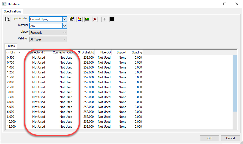
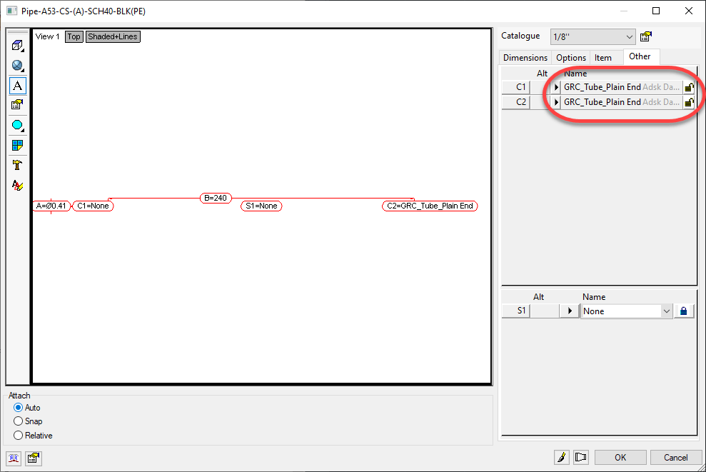
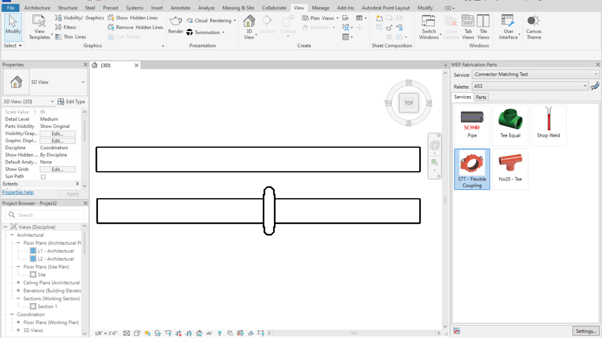
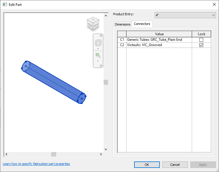
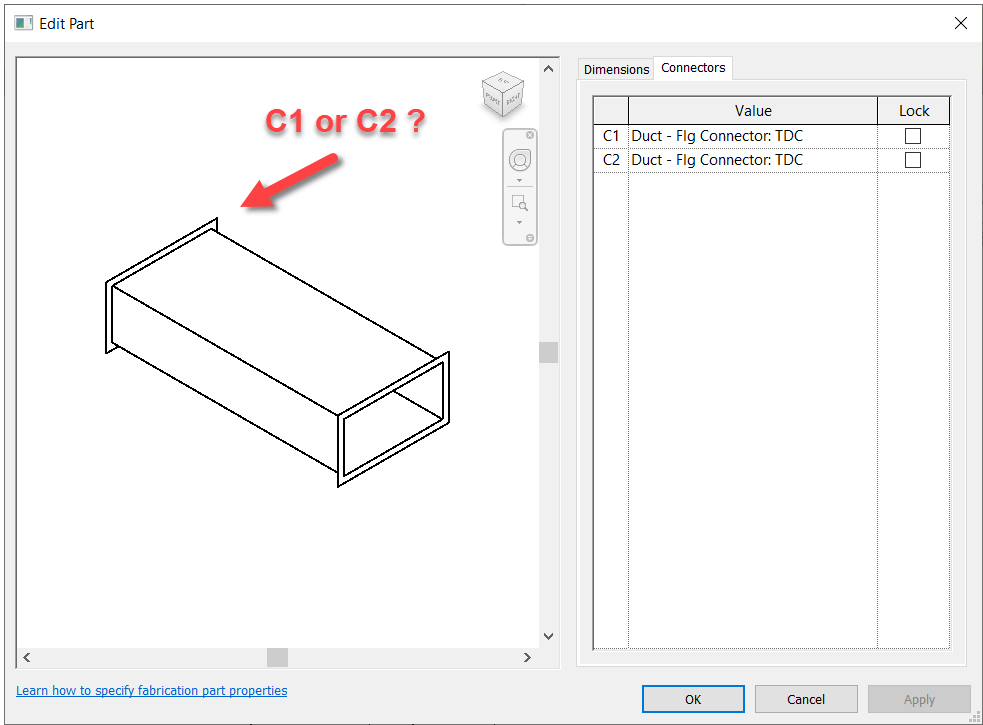
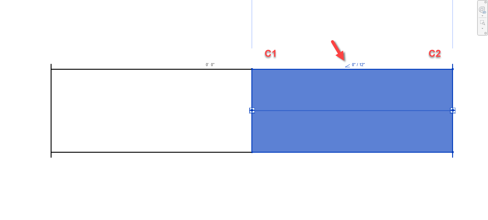
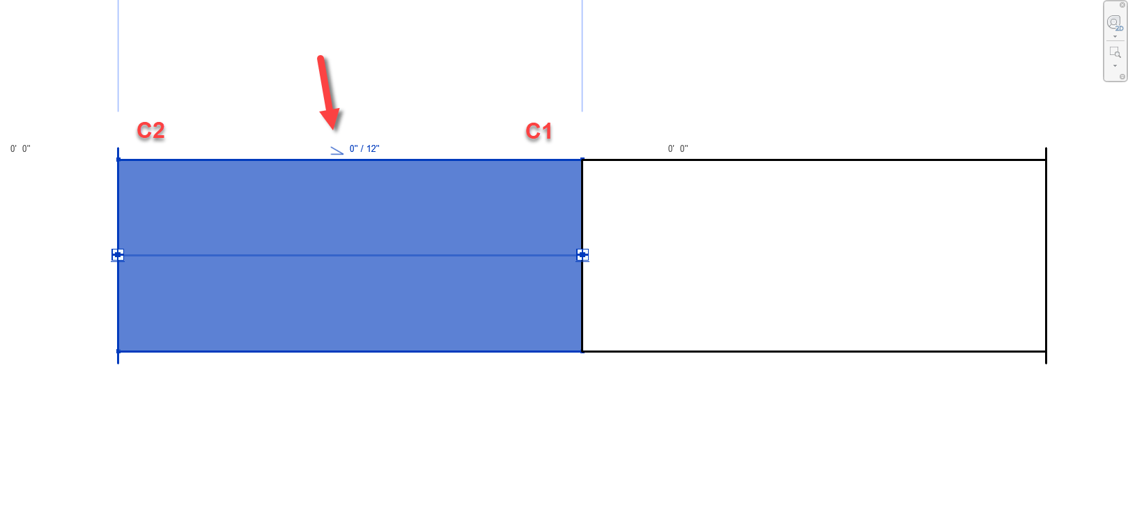
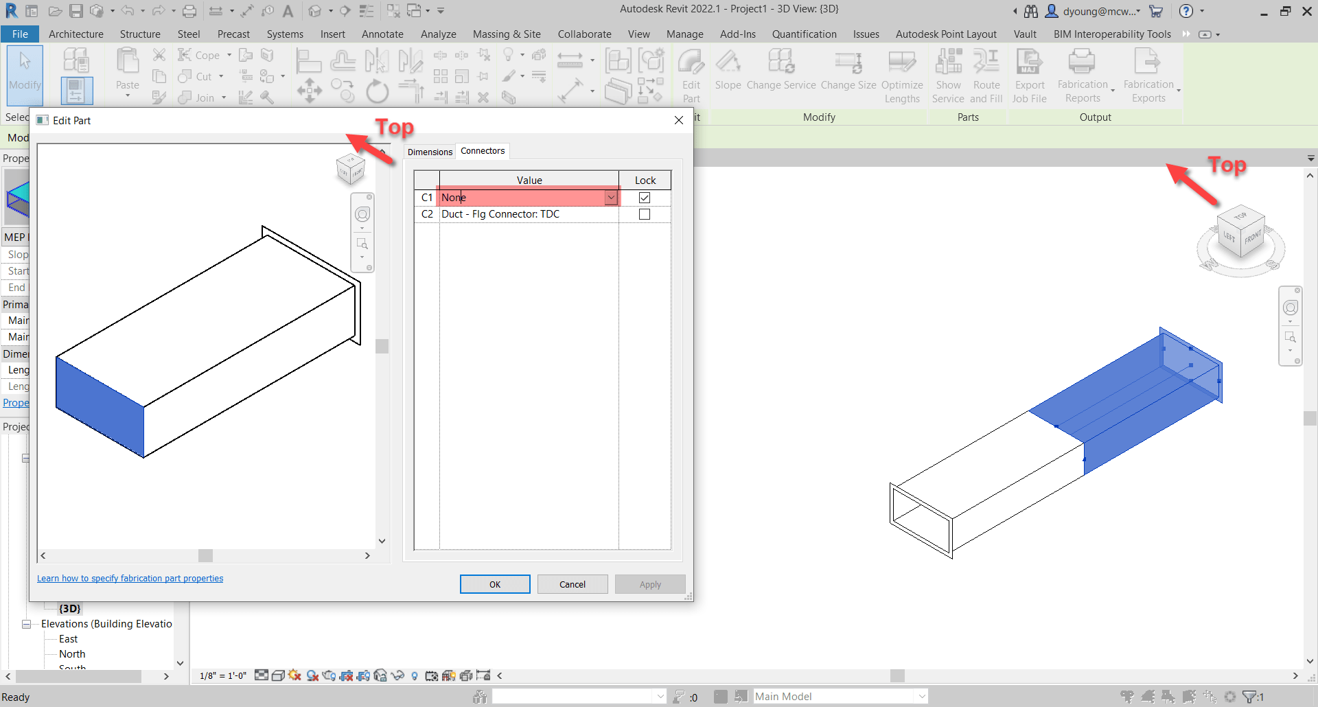
This session was presented by Claudia Calderon Quintero and Josh Churchill both of SSOE. This was literally the ONLY session at AU that covered anything related to Autodesk Fabrication. I wasn’t expecting much. Autodesk Fabrication has a pretty tight knit community of experts who’ve known each other for decades. Anyone speaking on Autodesk Fabrication that isn’t a known name is highly suspect.

That said, I was very surprised at this session. From an A&E perspective, they covered the topic very well. I’ve listened to Autodesk Fabrication presentations over the years with a lot of partial or incorrect information. But Claudia and Josh had a really rock solid presentation. Everything I heard was detailed, accurate and presented very well. I’m really impressed as well in their ability to get up to speed with Fabrication Parts as it’s not an easy thing to learn on your own when there’s not a lot of resources.

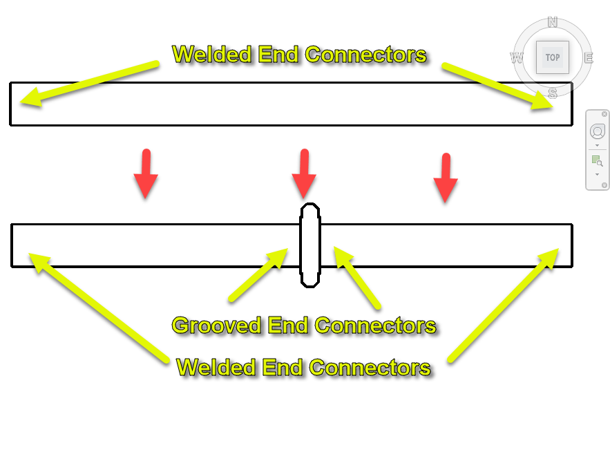
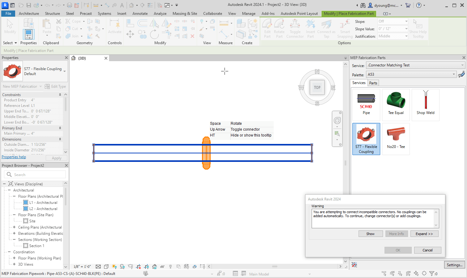
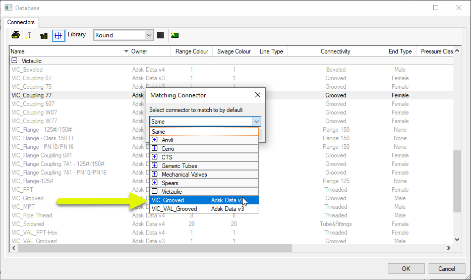
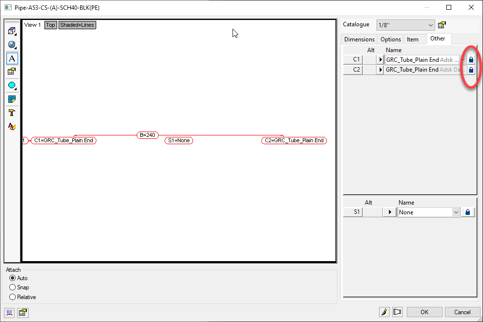
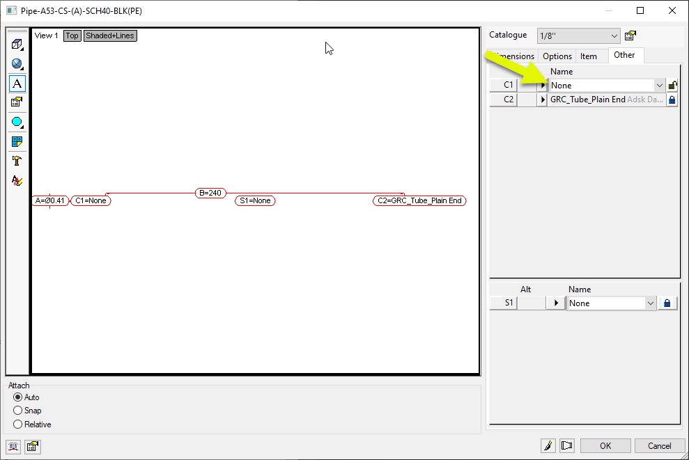
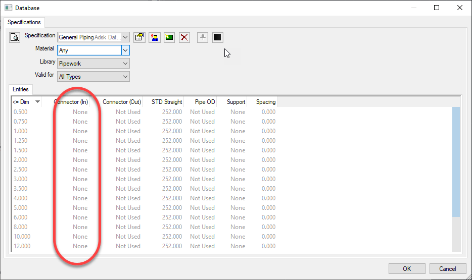
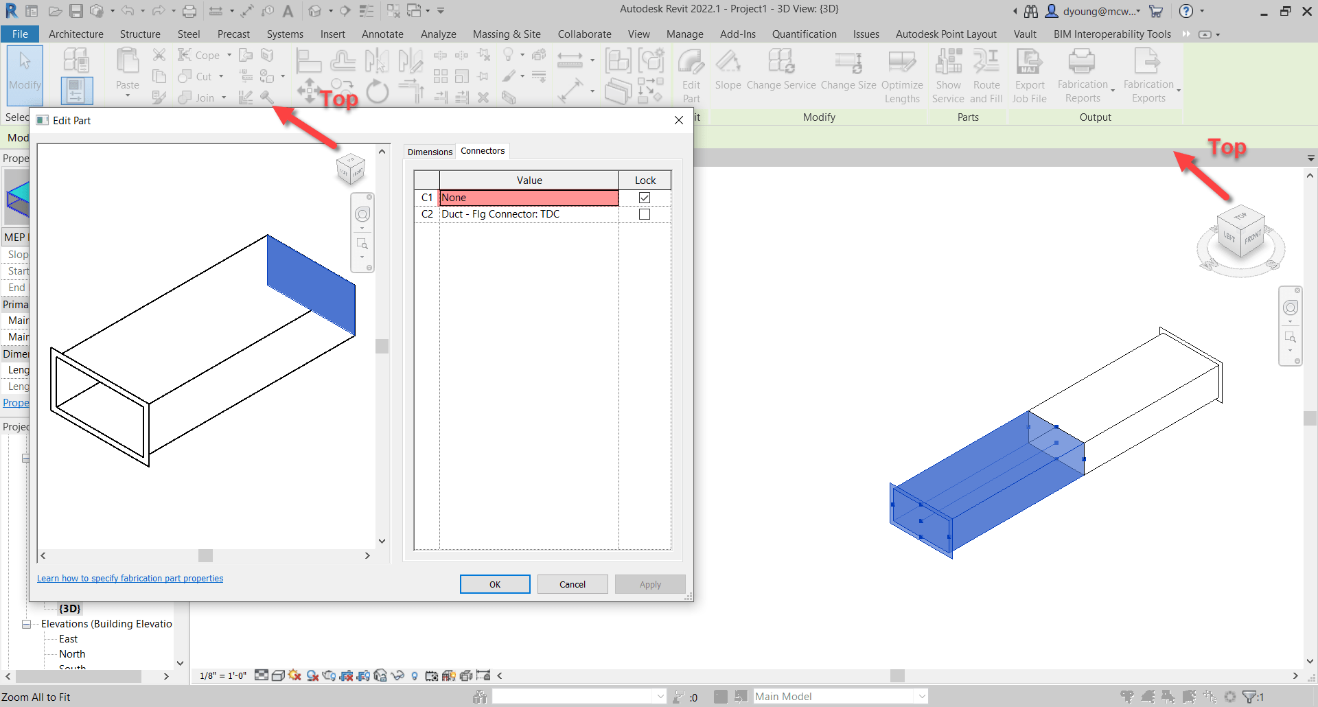
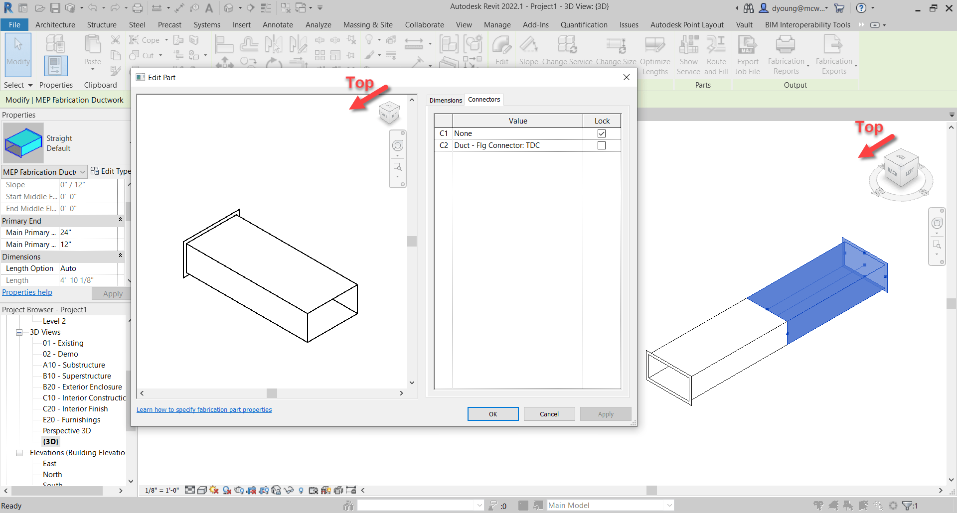
The essence of their presentation was using Fabrication Parts to create a “Specification” for industrial or process piping. As they said, anyone can make a “fabrication” level model with Revit Families…but anyone can also mess with those families. By using Fabrication Parts in Services, it get’s Revit a lot closer to a “Spec” driven design like you’d typically see in industrial piping with Plant3d with the content a little more protected from incorrect manipulation.

The key learning point here for me was the value of Fabrication Parts for a firm who’s NOT actually fabricating. I’ve struggled to see the value of Fabrication Parts for an Engineering only firm. Claudia and Josh easily explained this value to me. Something that having my head stuck in the actual “fabrication” and “construction” prevented me from seeing. Great job and great class.


Things We Can’t Do

Despite all Autodesk’s self proclamations of greatness and the legions of fans, there’s more holes in Autodesk’s strategy than a block of swiss cheese if your an MEP contractor. Here’s a few highlights of my observations from an MEP Contractor’s perspective….some will apply more broadly to other trades/domains.

Industrialized Construction, Inventor and Revit

One of my highlights of Autodesk University is to see the “Manufacturing Informed Design” team at Autodesk in the Expo Hall. I’ve spent 30 years straddling Construction and Manufacturing asking for this. It’s finally coming. Everything Autodesk has done to date seems to have been “Design” focused….pushing unbuildable design to Fabrication, Construction and Manufacturing. The Manufacturing Informed Design group flips that around…putting the PRODUCT front and center. This allows the Manufacturer or Fabricator to control how their product is used in Design….the way it always should have been.

Sure you can make a Revit family that represents a product. But anyone and everyone can mess with the RFA. You’ve can’t receive this model back and have any sense of reliability that’s it’s something you can manufacture from. What the Manufacturing Informed Design team does, is to make sure nobody in Revit can mess with your product. If your product is configurable, the consumer (Designer) is directed back to Autodesk’s web portal where they can control ONLY the aspects of the product the Manufacturer allows.

While the initial release will focus on Products produced in Inventor, there are plans to expand the “authoring” to other platforms like Fusion 360, Revit…perhaps even Solidworks and others. They want to make the logic authoring agnostic using code blocks similar to Inventor’s iLogic for configuration. In my opinion, this is the single most important step they could make toward “Productization” in construction.

So what’s the catch? Beta is estimated to be next year. That likely means 2024 Revit will be the first version (if not later…or even at all) that will have this capability. Except that means we’ll realistically be able to use this about 2027/2028. This industry loves to stay on old Revit versions and Autodesk now allows use up to 5 versions back. This means it’ll be 2028 by the time you find defects or functional limitations of 2024 versions. Except they won’t fix 2024 four years later…those fixes will come in 2029/2030 versions which you’ll start using about 2033/2034. That’s a 10 year development/feedback cycle. It’s just not sustainable. Keep this in mind when they tell you the industry is going to completely transform to products within a few short years. The tools just aren’t there to facilitate this in a wide scale manner.

Industrialized Construction and Fabrication Parts

As you can tell from the Inventor/Revit interoperability class I reported on earlier and the Manufacturing Informed Design group’s initiatives…Inventor is a key part of Autodesk’s Industrialized Construction Strategy.

Except that the vast majority of large MEP Fabricators are using Fabrication Parts. Fabrication Parts can be exported and brought into Inventor….except they look like shit and are unusable for manufacturing in the Inventor environment. Inventor and Fusion 360 are Solid Modelers. Fabrication Parts are NOT Solids…they’re surfaces. Poor quality surfaces at that. That was intentional…to keep AutoCAD/CADmep performant. Because Fabrication Parts know what they are (Pipe, Elbow, Tee, Valve, etc.) they have the proper data to fabricate from and don’t need heavy detailed graphics. You can place 10x more Fabrication Parts in Revit than RFA’s before seeing the same performance impact.

Until Autodesk bolts Fabrication Parts into Inventor (and I have no knowledge they’re even considering this) you’ll have to wait for the Manufacturing Informed Design team to allow Revit Authoring of Product. Who knows when that will be and when it does happen…what are the chances they even know how to manipulate a Fabrication Part? Most of Autodesk’s own Revit experts don’t even know what a Fabrication Part is let alone comprehend their value. Of the hundreds of data points Fabrication Parts hold…even their own Construction Cloud knows virtually nothing of the data. In short, the firms who have digitally fabricated from 3d models for nearly 30 years (MEP Contractors) are largely shut out of all Autodesk’s Industrialized Construction technology strategy.

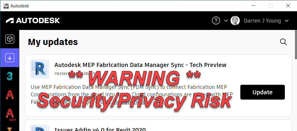
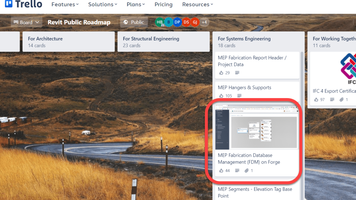
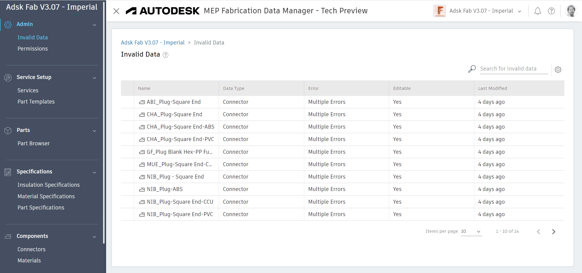
Speaking of Fabrication Parts…

I asked about the MEP Fabrication Data Manager Sync. The Technical Preview of Autodesk’s Cloud based Fabrication configuration manager. A 7+ year initiative that’s still not usable in any practical capacity. I asked when it would be “Done”.

“Who’s to say it’ll ever be done. Perhaps it keeps evolving.”

Fair enough. So I followed up…When will it evolve enough that MEP contractors will willing use it?

“Who’s to say it’s even going to be for that type of customer?”

That speaks volumes. Add to that the ONLY session at Autodesk University on Fabrication Parts in Revit was from an A/E firm that doesn’t build or fabricate, it’s another data point suggesting Autodesk doesn’t have a plan for MEP Contractors. Or they simply think they’ll all cease to exist in a “Productized / Industrialized” construction economy. Certainly MEP Contractor’s will need to evolve…but we’re not going away. Great opportunity for someone else to enter the market IMO.

Data Exchanges

Another focus of Autodesk is Cloud Enabled Data Exchanges. You don’t download or export a spreadsheet to order from Amazon.Com or to book a flight. This makes a lot of sense in many if not most ways. It’s the first step of breaking down those old obsolete concepts and barriers like “files” which have long outlived their usefulness. With so much work to do in this area, it’s unlikely Autodesk will make Fabrication Parts part of these data exchanges anytime soon….if ever. Products like GTP’s Stratus jump through huge hoops to mine the data they do. These exchanges aren’t anywhere close to possible in Autodesk’s Platform Solutions today. It’s my hope that these Cloud based data exchanges evolve enough to start breaking down those “version incompatibility” walls between Revit versions which will shorten that 10-year development cycle. At least that’s my hope….if I were to have any.
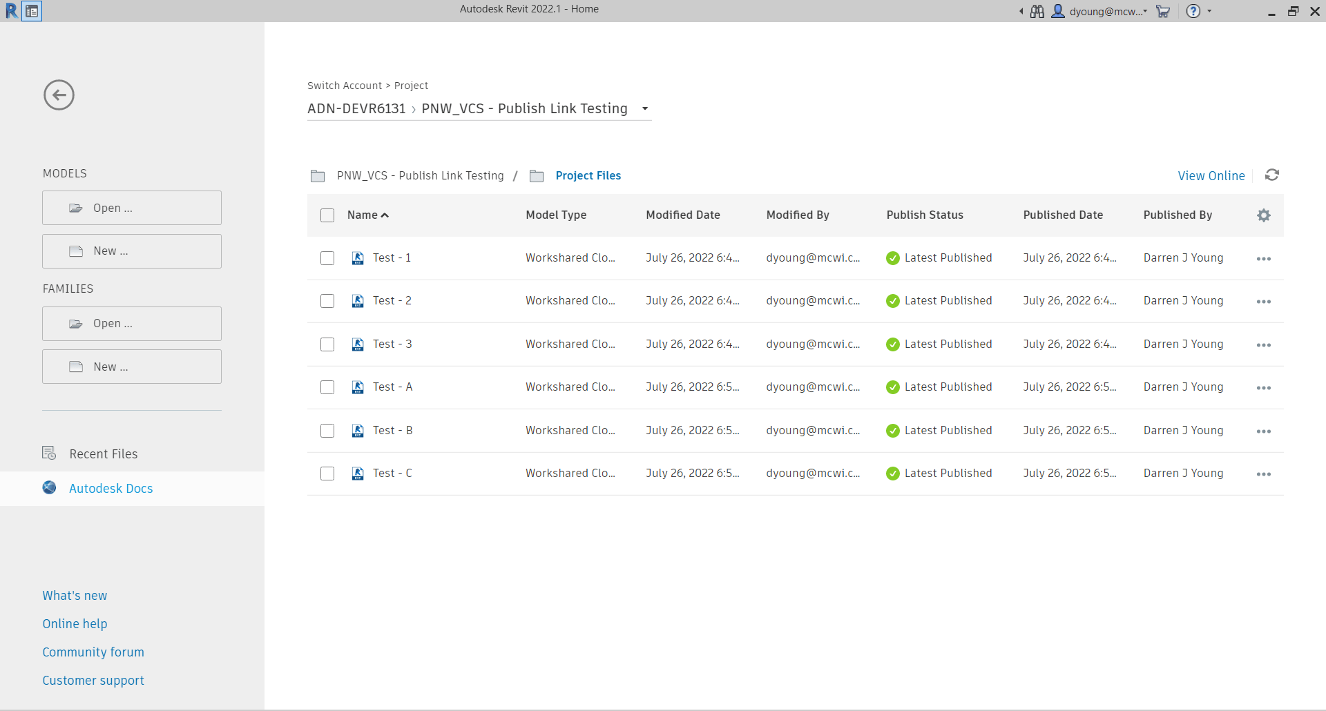
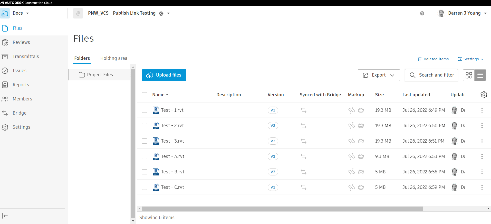
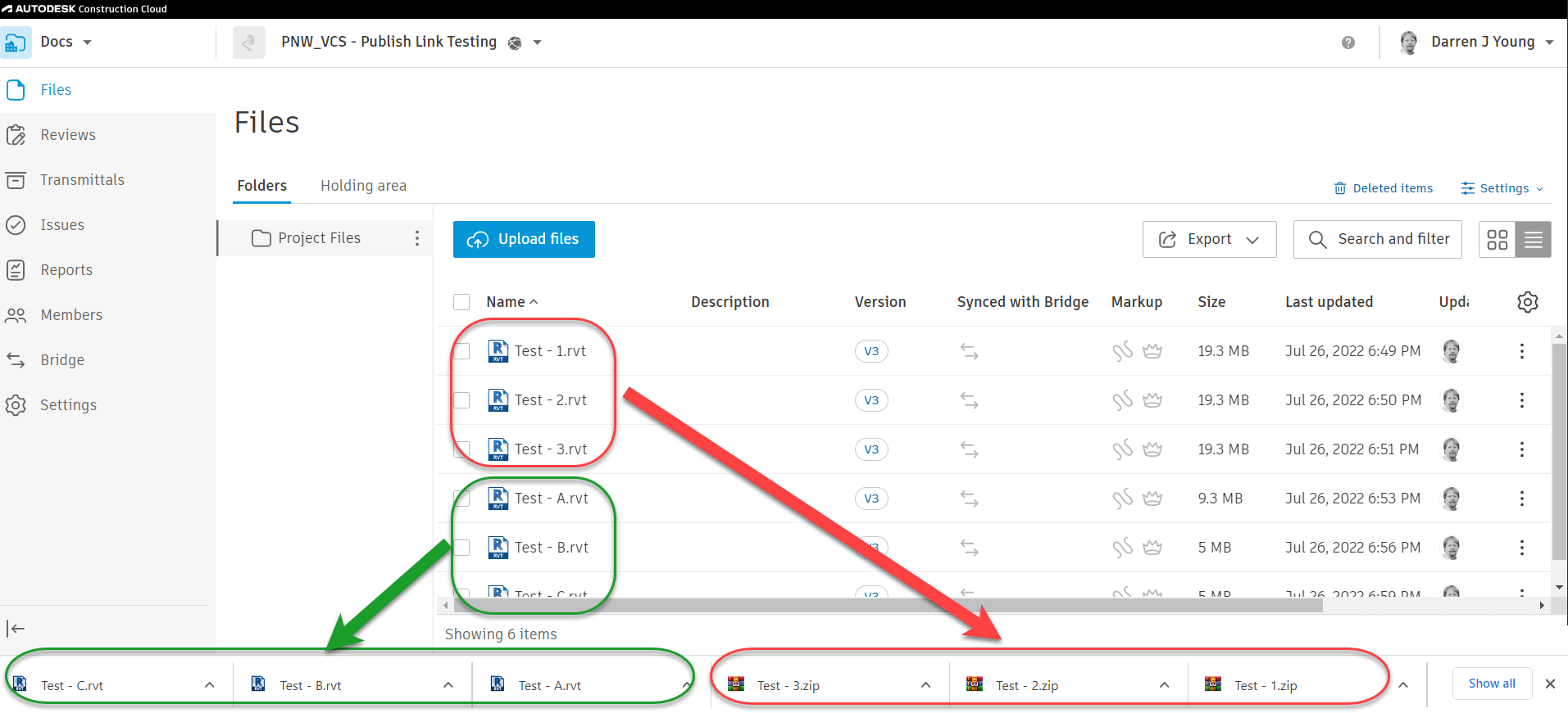
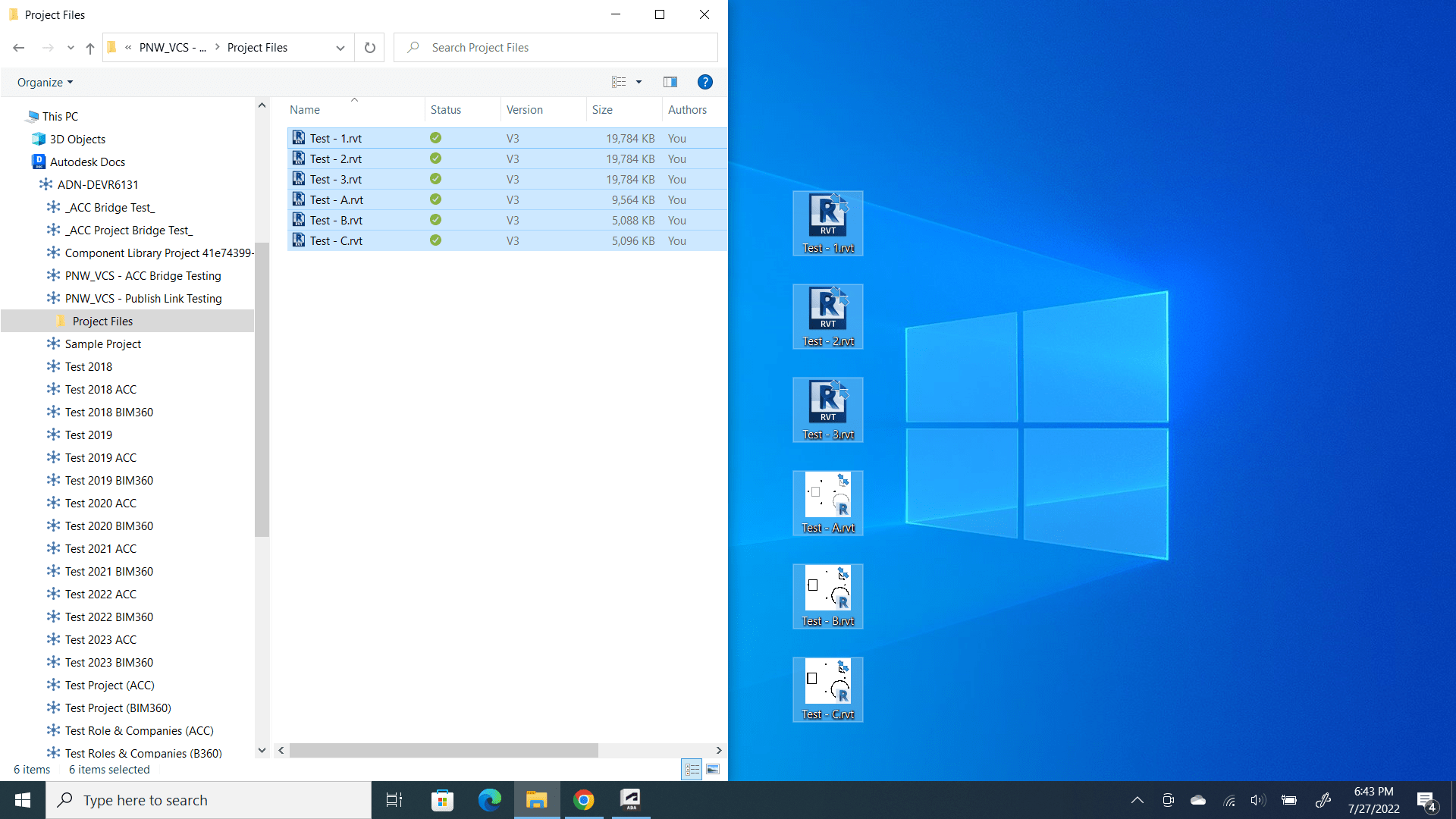
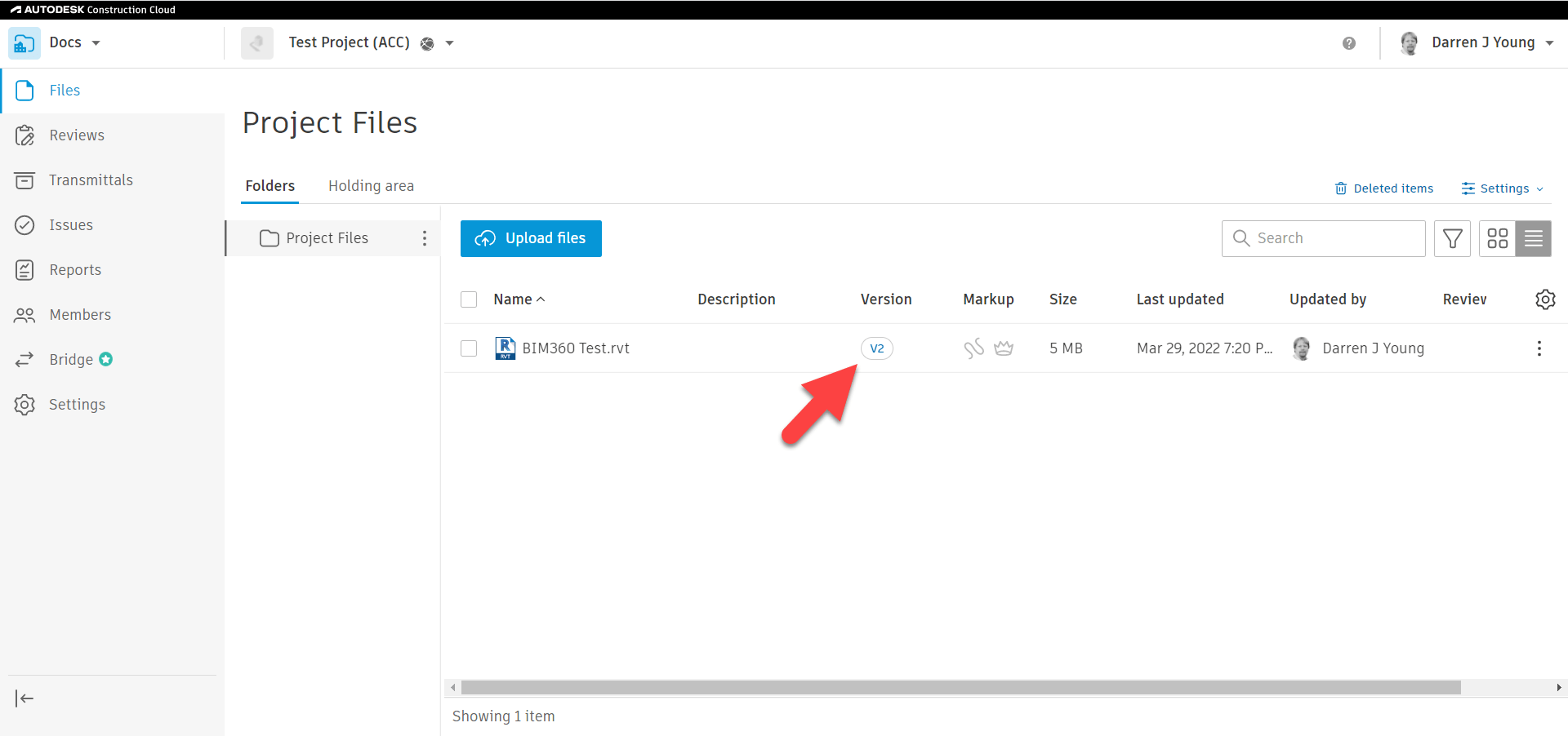
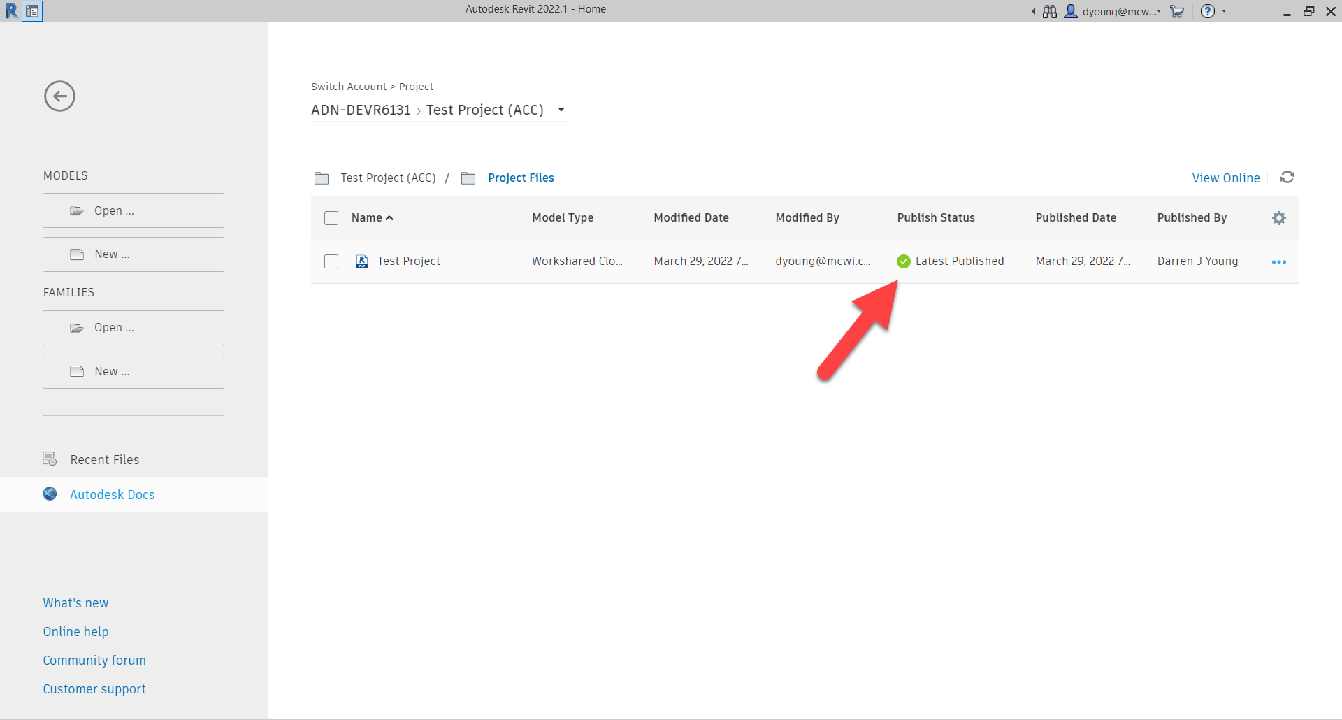
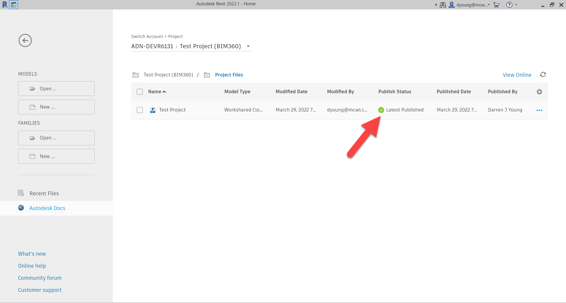
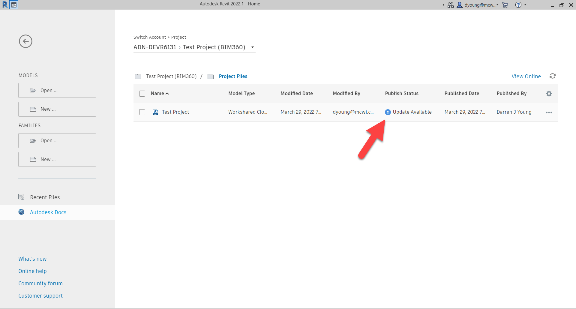
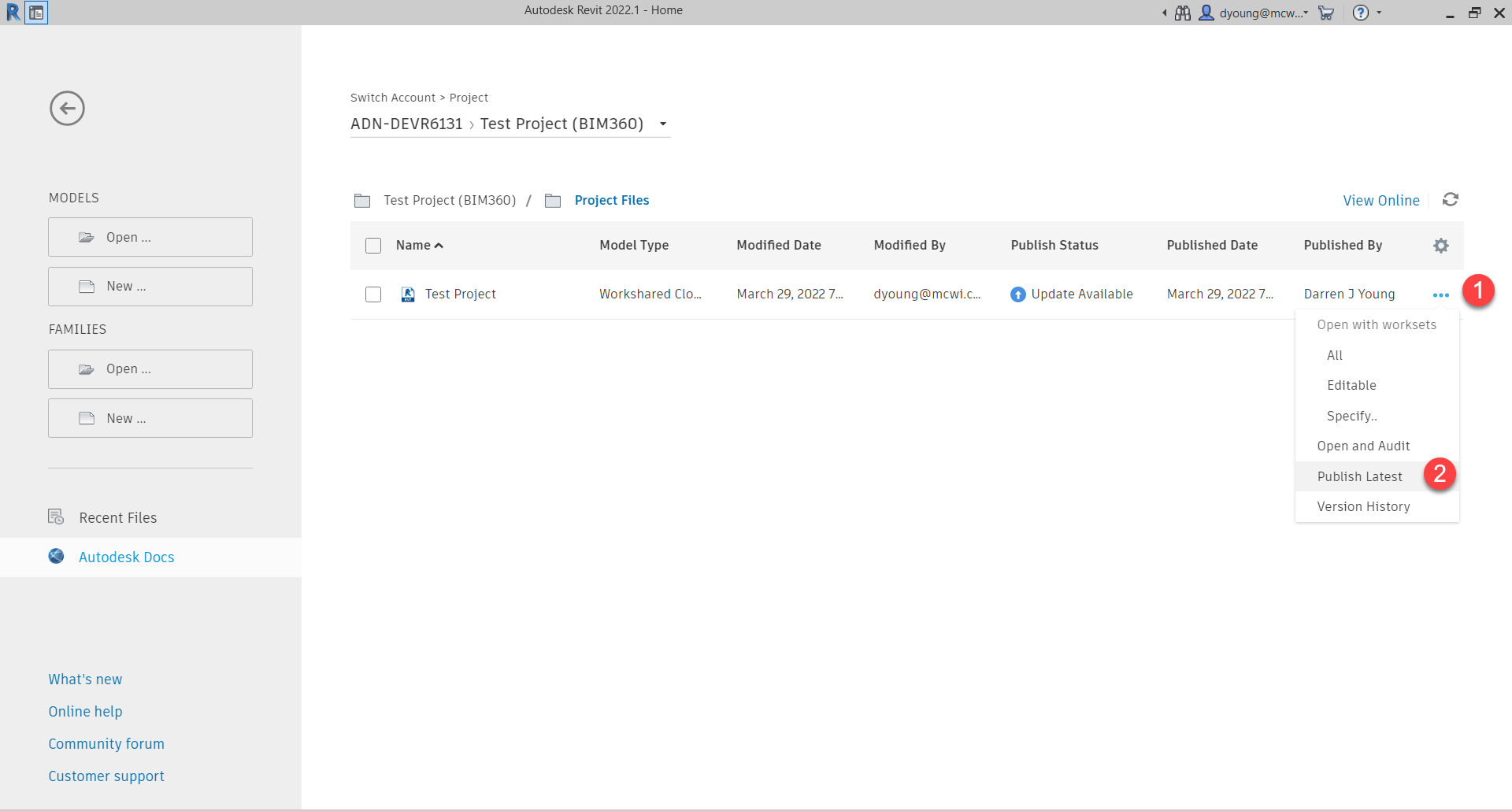
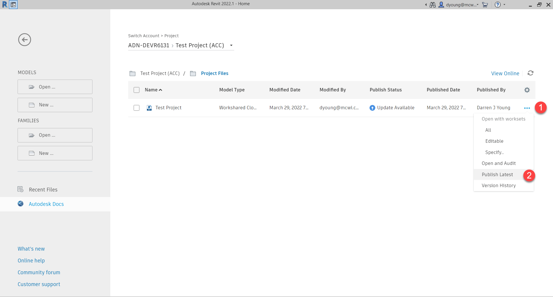
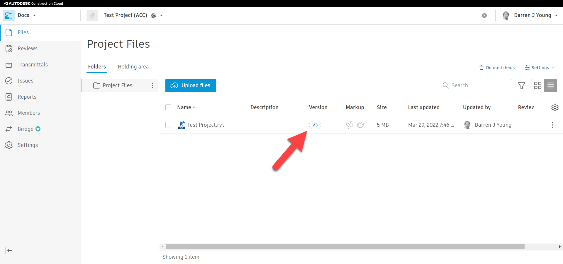
A Bridge to Nowhere

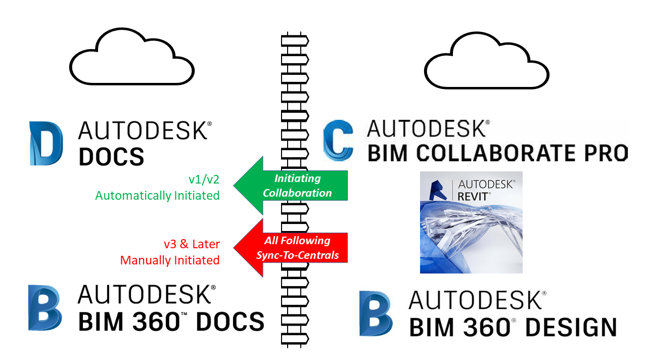
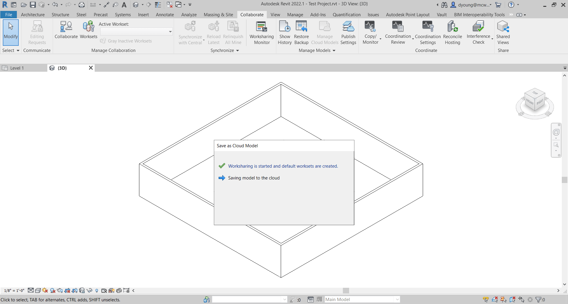
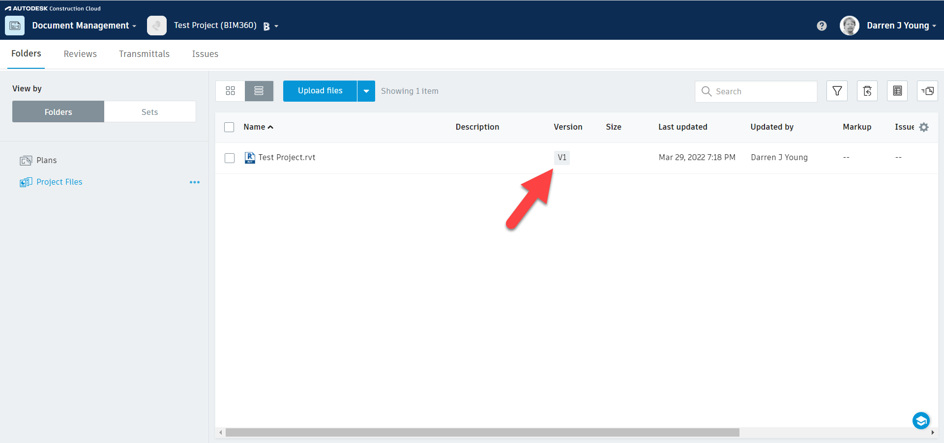
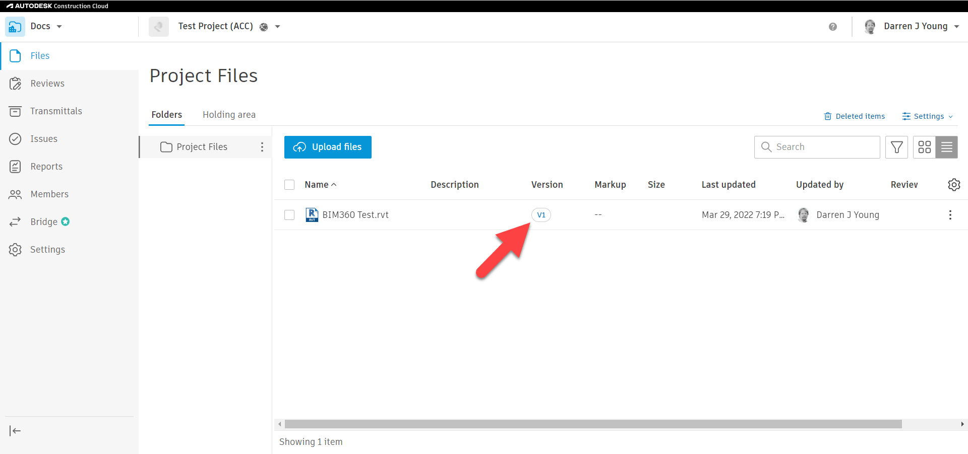
One of the Autodesk Construction Cloud (ACC) highlights is it’s “Bridge” functionality. It allows you to link/sync multiple ACC Accounts between customers. Except that it only works on “published” models in Docs. It doesn’t work on “Live” models with BIM360 Collaborate Pro like it needs to. It also doesn’t work on the “Data”, just the “files”. This limits the effectiveness of ACC which is why most BIM360/ACC projects I see are complete train wrecks in terms of their use of existing functionality and configuration. People using Desktop Connector to access non-collaborated models or host Central Workshared models that aren’t in Collaboration.

Rumor has it Autodesk is reworking Desktop Connector. I’m sure that’ll inject just as many problems as it solves. Autodesk simply doesn’t have robust feature sets in their products any longer. Merely enough features to keep you on the hook as they have guaranteed annual revenue now.


Future Speculation

Given everything I’ve seen and heard….and 30 years of observing the industry and correctly predicting much of what has really transpired, I have a few predications…

  1. Autodesk’s Cloud enabled Exchanges will eventually be monetized. You’ll pay for everything eventually. Pay to author…pay to report…pay to export.
  2. Autodesk will become the “Facebook” (Meta) of Design/Construction/Manufacturing data. That means everything you think of when you think Facebook….the good and bad.
  3. An API first strategy is NOT in the cards. Data Exchanges will always be limited compared to what Autodesk can do with them. This will allow them to control and maintain their market position limiting what others can do or and controlling how much they must pay.
  4. Old school data exchanges will eventually go away and everything will be required to use the Cloud to facilitate data exchanges. I don’t like it on principal but it makes sense and needs to happen.
  5. 3rd party developers traditionally thought of as Autodesk competitors will some day be customers to facilitate their interoperability with Autodesk.
  6. Industrialized Construction will not be as wide spread or come as quickly as Autodesk says. Autodesk will be the biggest limiting factor in this due to products suffering a drought of features and depth.

No need to cover the positive predictions….I touched on them earlier and Autodesk does a good job promoting them all on their own. They don’t need my help. My value is providing a more realistic perspective and timeline….IMO. Let’s hope I’m wrong on many of my predications.

Desktop Connector + Revit Cloud Models = Bad Idea

I’ve been seeing a recent trend in project teams. An increasing use of Autodesk Desktop Connector to link Revit Cloud Models. While it can and does work (sometimes), it’s a real bad idea and should be avoided unless absolutely needed. The reasons are subtle and nuanced. But those nuances are a make or break in terms of success.

I’ll try to explain as best I can. I’ll even give you steps you can do to reproduce this issue yourself. But first, let’s go over why Desktop Connector exists in the first place.

A Brief Desktop Connector History

Autodesk’s first attempt at a proper Cloud workflow for Revit was called Collaboration for Revit. It later became BIM360 Design and today is called BIM360 Collaborate Pro. Same idea…take a Revit model and manage it in the Cloud from Sync’d local data. Practically speaking, it’s a cloud version of Revit Server.

Back in those early days, you could link to other Revit cloud models. But Revit supports other types of links besides RVT files. So people would link to file servers. But in a collaborate environment, other teams didn’t have the same file servers or folder structures. Those other linked files linked DWG’s or IFC’s would break. So like the good technologist’s they are, BIM Managers started using services like Dropbox across the product team. Those non-Revit files were linked from there so the links would be common across of team members.

As a result, Autodesk later acknowledged the value in doing this and released it’s own ‘sync’d drive’ tool called Autodesk Desktop Connector. So that’s why it’s there. It’s intended to link non-Revit files or Revit files that are NOT cloud models.

One could argue that Autodesk should have just made Collaboration for Revit work with those other files types. I agree and it’s a nice thought. But it’s likely not the case because the Revit files you see on BIM360 Docs (now Autodesk Docs) are NOT the same files as are used by Revit’s Cloud collaboration tools. You can read more about that here (https://www.darrenjyoung.com/2022/03/29/the-2-sides-of-bim360-acc-docs/)

The False Alure of Desktop Connector

When I see Desktop Connector misused, the reason I’m given is usually the same. “We don’t want to Live Link models“. That’s to say, they don’t want to see daily changes from the other project teams in real time.

So that sounds reasonable. But if people would use BIM Collaborate Pro ‘properly’ this actually solves this problem and in a much more flexible way. BIM Collaborate Pro when setup and used properly allows 3 separate workflows or a combination of any of them….

  • Link to Live Models
  • Link to “Shared” copies of Models (only updates when the model owner chooses to share)
  • Link to “Consumed” copies of Models (only update when you consume a shared copy)

Yup. That’s it. Complete flexibility on how you link to other Revit Cloud Models. In short, if you’re linking to get away from updates you don’t control, it’s because you’re not using the BIM Collaborate Pro properly. More accurately, whoever is hosting the project did not set it up properly and you’re a mere casualty caught in the cross fire. Something most sub-contractors are very familiar with.

The True Appeal of Desktop Connector

There’s really another reason people use Desktop Connector for Revit Cloud models. A result of Autodesk’s flawed logic that everyone on the project should be on the same platform, same project and same account. While it makes sense at a high level, it also means all other project teams who aren’t the hosting company are limited to the willingness and/or capabilities of the hosting company.

Taking that into account, one aspect of Desktop Connector is that you can link ‘between’ BIM360 or ACC (Autodesk Construction Cloud) accounts. That is, you can link files in your account, to project files in another team’s account. This cross account linking is NOT available in BIM Collaborate Pro with Cloud models or Cloud Workshared models but it is in the Desktop Connector.

When you put this all together, this means companies can link to files from other companies but still control their own models on their own account. And they’re not live linked either. This is why we’re seeing a proliferation in Desktop Connector usage with Revit Cloud Models.

The new Autodesk Construction Cloud has some “Bridge” functionality designed to facilitate this. I tested the Bridge functionality when it first came out. It didn’t work as required, expected or as advertised IMO. It may or may not have improved since then but that’s not the point of this article. The point of this article is about linking to Revit Cloud models from Desktop Connector. Why it’s problematic, not a recommended best practice and why it should be avoided.

The Desktop Connector Problem

To demonstrate the problem, we’ll use two separate sets of 3 Revit files each linked to each other within the set like the following…

  • Set 1 (problem set)
    • Test – 1.rvt (Link to Test – 2.rvt & Test – 3.rvt)
    • Test – 2.rvt (Link to Test – 1.rvt & Test – 3.rvt)
    • Test – 3.rvt (Link to Test – 1.rvt & Test – 2.rvt)
  • Set 2 (working set)
    • Test – A.rvt (Link to Test – B.rvt & Test – C.rvt)
    • Test – B.rvt (Link to Test – A.rvt & Test – C.rvt)
    • Test – C.rvt (Link to Test – A.rvt & Test – B.rvt)

Each Revit model is a Cloud Workshared Model. (a standard Cloud Model would function the same for this issue). You can tell they’re Cloud Models be viewing them in Revit’s interface like shown in the following image…

If any of the Revit files were not Cloud Models, they wouldn’t appear here in Revit but would appear from the BIM360 or ACC web interface. You can see in the following image, those same files are listed in the web interface. They were all published so the version in Autodesk Docs displays the same contents as is available in BIM Collaborate Pro.

So far, all seems fine. The files you see in the BIM360 or ACC interface are the same ones that are available in Desktop Connector. Now here’s where the issues starts to manifest itself.

Take a look at what happens when we try to download the Revit Models from the web interface. Set 1, the numerical set download as ZIP files. Set 2 on the other hand, that alphabetic models download as Revit files.

Perhaps you’ve seen this before. I know many users who assume that the ZIP file downloads are there because the Revit files contain links. Because a non-linked model always downloads as an RVT. Other users think it’s part of the whole “Share/Consume” workflow of BIM Collaborate Pro. Both explanations are technically incorrect.

The following image shows the files and their downloaded names. Keep in mind that each set is a model collaborated in the Cloud the exact same way and linked the exact same way. In fact, they themselves are not linked from the Desktop Connector either. They’re linked properly through the “External Resources”. Aside from the files names, they are identical in every way.

Further Proof – RVT Doesn’t Mean RVT

To further complicate matters, Desktop Connector displays all the files as RVT files even though some are ZIP files. Here’s how to test that out. First, we’ll use Windows File Explorer to select and copy all the files to the desktop. You can see the first hints of something being wrong in the following image…

Notice that all the files are named RVT just like was displayed in the Web Interface of BIM360 / ACC. However you can also see the icons are different between the two sets of files. The Revit files display their preview. The others display the icon because if the RVT extension because it can’t find a Revit preview. So let’s test our theory that some of these are actually ZIP files named wrong.

We’ll rename all the files to the ZIP extension and attempt to open them. The following images shows the renamed files. It also shows happens when you attempt to open the ZIP for one of files from Set 1 (Test – 1.rvt, Test – 2.rvt & Test – 3.rvt).

You can see when attempting to open the file TEST – 1.rvt.zip (remember we renamed to a ZIP) it shows the contents. It contains the Revit file and the links that Revit file uses.

Now let’s try the same thing with another file. This time. we’ll use the file Test – A.rvt.zip from Set 2.

You can see that despite renaming the file as a ZIP file, Test – A.rv.zip will not open and displays no contents. That’s because it is indeed not a ZIP file.

Summary of the Desktop Conector Problem

To summarize what we just saw, the web interface to BIM360 / ACC as well as Desktop Connector showed that all the files were RVT files. But upon testing with 2 different methods (web download & copy/rename from Desktop Connector) we can see that the two sets of files are not the same.

Set 1 is comprised of ZIP files despite showing their name as RVT and Set 2 are actual RVT files.

We can perform one further test to see if this is the case, We can start a new Revit file and try to link one of each set from the Desktop Connector. The following images shows just that…

You can see we were able to successfully link Test – A.rvt (from Set 2) using the Desktop Connector. But when we try to link Test – 1.rvt (from Set 1) we get an error, Failed to open document.

Again, this is because despite what you see (the RVT file extension), the file is actually a ZIP file. This is the root of the problem with using Desktop Connector to link Cloud Models. Linking non-cloud Revit models is not a problem. More in that in the next section when we cover “How” and “Why” this happens.

The How and Why

The issue of when BIM360 / ACC is using a ZIP file vs. a RVT file behind the scenes is actually quite predictable and a little controllable. So let’s take a look. It might be a little difficult to understand but we’ll try explain anyway. We’ll then follow-up with the steps to do it yourself.

At the root of the issue is that the Cloud model Revit uses is a separate file that the one you see in BIM360 / ACC Docs and Desktop Connector. You choose when to “publish” the one that shows up in BIM360 / ACC. And here’s where it starts to get complicated. We’ll use the names of the samples models to make it a little more clear.

If you have cloud model Test – 1.rvt open, and you link to cloud model Test – 2.rvt, if cloud model Test – 2.rvt has changes that are unpublished to BIM360 / ACC Docs when you publish Test – 1.rvt to BIM360 / ACC Docs, Test – 1.rvt will be a ZIP file.

On the other hand, if you link to cloud model Test – 2.rvt and it’s latest version is published to BIM360 / ACC Docs then when you publish Test – 1.rvt and download it, it will be a RVT file.

Did you catch that? Whether a Cloud model ends up as a ZIP vs. a RVT depends on the Publish Status of the Cloud models it links when you publish it.

Let’s look at that visually. The below image shows the 3 models from Set 1. Notice how none of them have the current version published. When you publish one of these, or even all three of these you’ll end up with a ZIP file.

Again, the issue is that you linked a cloud model in Revit when that cloud model had unpublished changes. Even if you published all of the models now, you’ll still get ZIP files with downloads and Desktop Connector. That’s because when they were published, there were unpublished changes which made them ZIP files. Further publishes will always make more ZIP files because they now reference Cloud models who’s Published versions are ZIP files not RVT. Yea…that’s a bit complicated. Just know that once you start getting ZIP Downloads, they’ll stay that way. From here on out, there’s only one way to fix it which we’ll get to momentarily.

How Not to get a ZIP

Now here’s where the process get’s slightly different if you want a RVT. The difference here is when you go to link the Cloud model, you need to make sure the file(s) you’re linking don’t have unpublish changes when you publish it. So when you have Test – A.rvt open, make sure Test – B.rvt doesn’t have unpublished changes, if it does, Test – B.rvt needs to be published before Test – A.rvt. Then when you then publish Test – A.rvt it will download as an RVT and Desktop Connector will be a ‘real’ RVT file.

So that sounds simple. Just make sure when you link the cloud model that’s it’s most recent version is published. But it’s not that simple. At any point in the future if one of the linked files is not published when you publish the model, you’re back to the ZIP file again and it stays that way. Until you fix it.

Unzipping the ZIP

If you ever link a cloud model that has unpublished changes you’ll end up with ZIP files. Further more, if at any point you publish you model, any one of the linked cloud models has unpublished changes, you’ll get a ZIP file again. And it won’t get fixed again easily.

This is why you should NOT link to cloud models from Desktop Connector. Because you’re relying on the author to understand this and know what to do. In fact, in the course of a real project, it’s damn near impossible to make sure you’re not going to get a ZIP. You can’t control when the project teams make changes and publish.

However, if you do want to fix the ZIP problem, here’s the process.

  1. Open your Revit model and “unload” (not remove) and cloud model links. Save/Sync and publish the model.
  2. Repeat Step 2 for all of the linked Cloud model. Make sure none have the links loaded.
  3. Once all models have their links unloaded, republish them all.
  4. Reopen one of the models and reload the links. Save/Sync the model. One model only.
  5. Now Publish the model and wait for publish to complete before doing any more models.
  6. Repeat steps 4 and 5 for the remaining models.

So that’s the process to “fix” the issue. Each model needs to be republished with none of the cloud model links loaded. You then open one, sync and publish each model. If you do save/sync more than one model before publishing again, you’re back to the ZIP files.

Try It Yourself

This issue is a bit nuanced…what makes a ZIP files vs a RVT. An even when its a ZIP, The web site and Desktop Connector misleadingly tell you it’s an RVT. And if you do have it working, it’s still fragile and breaks easily. Which is why it’s recommended to NOT use Desktop Connector to link to Revit Cloud Models.

If you really want to understand the issue, it’s best to try it yourself. You can do it with just 2 files. Here’s how. Follow these steps exactly.

  • Step 1 – Create file A in Revit and save as a Cloud model or Cloud Workshared model.
  • Step 2 – Close file A.
  • Step 3 – Create file B in Revit and save as a Cloud model or Cloud Workshared model.
  • Step 4 – Close file B.
  • Step 6 – Open file A and link file B using the “External Resources” (not Desktop Connector)
  • Step 7 – Save/Sync file A and close.
  • Step 8 – Open file B and link file A using the “External Resources” (not Desktop Connector)
  • Step 9 – Save/Sync file B and close.
  • Step 10 – Publish both files so their latest version appear in BIM360 / ACC Docs.
  • Step 11 – Try downloading with model from the web and you’ll see they’re zip files.
  • – – You’ve now recreated the process which makes the ZIP files – –
  • Step 12 – Open file A and unload the link to file B.
  • Step 13 – Save/Sync and Close file A
  • Step 14 – Open file B and unload the link to file A.
  • Step 15 – Save/Sync and Close file B.
  • Step 16 – Publish both models. (when you publish doesn’t matter with links unloaded)
  • – – Both models are now published with no Cloud model Links. This clears the ZIP issue. – –
  • Step 17 – Open file A and reload the links to file B.
  • Step 18 – Save/Sync and Close file A.
  • Step 19 – Publish file A and wait for it to complete before continuing. This is important. It’s linked to a file B. While file B has no links loaded, it has all it’s changes published (the critical step)
  • Step 20 – Open file B and reload the links to file A.
  • Step 21 – Save/Sync and Close file B.
  • Step 22 – Publish file B and wait for it to complete before continuing. This file is linked to file A which does have links, but it also has all of it’s changes published too.
  • Step 23 – Try downloading the models now. You should get a RVT file instead of a ZIP.
  • – – Both models are now published but are now accessible from Desktop Connector or downloadable as RVT files – –

It sounds like a lot of steps but it’s fairly quick to do. Perform these steps and you’ll get a better idea how the issue. Any time you have changes in multiple models before you publish, you’ll see the ZIP show up. If you change and publish a single model at a time, you’ll have RVT files. But also note, once you get the ZIP files, you’ll need to unload the links on all the files, republish and then open, reload and publish one at a time to clear the issue.

Summary

So that’s it. If you understand the issue, you’ll see how easy it is to have the ZIP issue show up. And that’s when linking from Desktop Connector breaks. And in the course of a project, it’s easy for others doing what I’ve explained above to break YOUR link to THEIR model when you use Desktop Connector.

So don’t use it to link Revit Cloud models if at all possible. If you’d like further reading on this, check out these Autodesk Knowledge Base articles…

“Failed to open document” when adding links to a Revit model through Desktop Connector.

Fabrication References – 2023 Update

Fabrication 2023 is out. I’ve updated all the reference information to include 2023 formats. As has been the trend the last few years, little has changed. Summary below…

The 2 Sides of BIM360/Autodesk Construction Cloud

I see a lot of people confused about how BIM360 Docs / Autodesk Docs works when used with BIM360 Design or BIM Collaborate Pro and Revit. It doesn’t help any that Autodesk repeatedly refers to ‘Single Source of Truth‘ as one of the benefits. While BIM360/ACC does help provide a ‘Single Source of Truth‘, it’s not quite as simple as it seems.

There’s 2 Models…Not 1.

Yes, you heard me right. There’s actually 2 models and a virtual ‘Fence‘ between them. One used by BIM360 Design / BIM Collaborate Pro and another completely separate model by BIM360 Docs / Autodesk Docs. This graphics might explain it a little better…

How Things Really Work

Before anyone creates anything, Docs has no files. The following images show BIM360 Docs on the feft and Autodesk Construction Cloud on the right. This will help you see subtle differences however things really work the same.

Next, you model something in Revit and Initiate Collaboration…

Once Collaboration to the Cloud is Complete, if you look at BIM360 Docs / Autodesk Docs quickly you’ll see the file shows up as Version 1 (v1). At this point, you can’t click on the file to view it. Autodesk’s system is merely creating a placeholder while it continues to process the model in the background.

If you wait long enough, you’ll see that the files then update as Version 2 (v2). Once they’re listed as v2, they can be clicked and viewed in the Cloud. Despite saying v2, you really only initiated collaborate once from Revit. v1 was the initial file placeholder and v2 is the finished model that’s processed.

One reason for the confusion is that this v2 model shows up automatically. The common assumption is that it’s the same model as the one you opened in Revit. But that is NOT the case. The v2 model is actually a ‘Processed Copy‘ of the model you had open in Revit. That’s why it took a little while for the v2 model to show up in Docs.

The next time you open the models in Revit, you can see that it shows the models as ‘Latest Published‘. Note that you should be opening the models through BIM360 Design / BIM Collaborate Pro and NOT from the Desktop Connector. More about that later. For now, you can see the models listed when you try to open them in Revit.

If you open these models, they would look exactly the same as those viewed from Docs on the Web. The next thing that happens is people change the model and Sync to Central. This will continue for the entire development of the model. Pretty normal stuff.

Despite syncing changes to the cloud, if you view the models from the web interface of Docs, they’ll still say v2 and show the original published model.

In fact, if you were to close and then try to reopen the model from Revit, you might notice that it now says there’s an ‘Update Available‘. Note: You might need to click the ‘Refresh the current project‘ icon in the upper right to refresh the status. If you haven’t browsed to a different folder/project or restarted Revit the project status cache might be stale and need the refresh.

When an update is available, YOU as the model author can choose when to push those changes to BIM360 Docs / Autodesk Docs. This is why there’s really ‘two sides‘ to models in BIM360. It’s intentionally this way to put you in control. You can control IF and/or WHEN to release your changes to the rest of your team for viewing. After all, you don’t want them to view your partial updates while you’re still working through issues.

You can choose to update the models right from that same interface. Click the ellipsis button to the right of the file entry and select ‘Publish Latest‘.

Once you select to publish the latest version, you’ll be prompted for a confirmation with some added details. You’ll then see the interface in Revit show it’s processing. Once it’s finished processing, you’ll be able to open the model again in Revit. If you look back at BIM360 Docs / Autodesk Docs once processing is done, you’ll see the file(s) there are now listed as Version 3 (v3)

At this point, your web view of the model in BIM360 Docs / Autodesk Docs is the same as when you open it in Revit. That is, until you make more changes and Sync to Central again. Once you have new sync’d changes, you’ll have to publish to Docs again. But only when you’re ready for the rest of the team to view the model.

BIM360 / Autodesk Desktop Connector Warning

It should be noted that the Desktop Connector displays what’s in BIM360 Docs / Autodesk Docs. It does NOT give you access to what you’re currently modeling in Revit with BIM360 Design / BIM Collaborate Pro. This may be perfectly well what you want when linking in a model from another team. But if you want their Live updates, you’ll want to Link from BIM360 Design / BIM Collaborate Pro.

Note that Design Collaboration does have advanced features for collaboration. It’s beyond the scope of this post but highly recommended you look into it.

I hope this helps you understand a little better about how BIM360 Docs / Autodesk Docs does and doesn’t relate to BIM360 Design / BIM Collaborate Pro. Just remember, it’s NOT the same model, it’s a published copy. The only time it shows up automatically in BIM360 Docs / Autodesk Docs is when you initiate collaboration for the first time in Revit. All other Sync to Central updates won’t show up in Docs without an intentional Publish by you or another team member.

Review/Warning – MEP Fabrication Data Manager Sync (Technical Preview)

On March 23, 2022, Autodesk released the “MEP Fabrication Data Manager Sync – Technical Preview”. That same day, I posted to several sources a warning regarding a risk in using this tool. In this review, I’ll go over the risks shortcomings as I see them along with what background I can share that’s not covered under NDA. I’ll also address Autodesk’s public response to my warning.


What is the MEP Fabrication Data Manager Sync?

Let’s start with a little background. What is the MEP Fabrication Manager Sync? This is a tool designed to Sync your Autodesk Fabrication configuration from the Cloud to your local system.

But Configuration isn’t in the Cloud you may say. Well, that’s part of the plan too.

Why would we want to do that?

The Autodesk Fabrication configuration is complex and powerful but also fragile and bug ridden beast. Because of this it’s difficult for Autodesk to make changes and fixes. If you recall, in their last big restructuring, they terminated many of the developers who were customer advocates and knew the code. So attempting to advance just about anything it to the ‘Next Level’ risks injecting a LOT of defects into the products we use. If you’re a Fabrication user, you all know what I’m taking about. You’ve lived it.

Enter their ‘Cloud’ strategy to put the Configuration in the Cloud. There, they can put it in a safe environment, refactor it, rewire it and surround it with digital bubble wrap to product it’s integrity.

This has actually been on the “Public Revit Roadmap” for a long time. I believe it even predates the existence of the public roadmap.

This strategy is one reason why Revit Fabrication parts had had little added development other than token improvements since about 2018. Lets face it, if they were to build it from scratch today, they’d do it differently then it was 20 plus years ago when CADmep came out. Makes complete sense what they want to do.

But as anyone with even the slightest electrical charge in their skull knows, you can’t put the configuration in the Cloud and have a Desktop product access it and hope to have any shred of performance. Hence, the “sync” tool to pull it back down.

So to summarize, Autodesk’s Cloud strategy for Fabrication is to push it to the Cloud where it can be protected and enhanced but not used. And then they’ve built a tool to sync it back down locally for use in Revit only….for piping only….only for your company…only if you never need a new fitting…only if you don’t use ESTmep, CADmep or CAMduct.


What’s Wrong with FDM?

There’s a long list of things wrong with what was released. Here’s a high-level overview.

  • Major Issues and Limitations are NOT disclosed.
  • FDM is NOT Disclosed as “Beta” or “Not for Production”
  • Estimating/Labor data easily distributed to others with no ability to recall it.
  • Only a single “owner” of a configuration with no way to change the owner.
  • Anyone can easily upload your Configuration and use or share it with anyone.
  • No new Parts, Seams, Dampers, Stiffeners, Supports, Ancillaries, etc.
  • Once uploaded, no way to “Re-Upload”
  • No interoperability to CADmep, CAMduct or ESTmep
  • Install Errors

Limitation & Issues Disclosure

There’s a lot of limitations with FDM and the Sync tool. Do NOT make the assumption that their list of limitations and issues in the help file are in any way near complete or comprehensive. There’s so little covered that it makes it appear the problems are trivial. They are not. It’s embarrassing how little effort they put into documenting this. You really need to read everything and infer a lot based on what’s said and not said. This is the only way to get a full picture and use this product with minimal risk.


Is FDM a Beta or Complete Product?

You may have seen Autodesk product manager Martin Schmit’s response to my post that FDM and the Sync tool are Beta and shouldn’t be used in production. You can see them here…

https://forums.autodesk.com/t5/revit-mep-forum/warning-mep-fabrication-data-manager-technical-preview/td-p/11025492

http://www.xtracad.com/forum/index.php/topic,17023.0.html

That’s flat out bullshit. Here’s why…

  1. The description in the Autodesk Desktop App does NOT say or mention ‘Beta’. So no, it’s not listed as a Beta here. Other Technical Previews in other products didn’t provide ‘Beta’ notices either of the ones I saw.
  2. During install or once installed, review the ‘Terms of Service’ in the Sync Tool. It contains 2,709 characters / 501 words and not a single instance of the term ‘Beta’. Not listed as a beta here either.
  3. The initial help file/Release Notes contained 14,290 characters / 2,698 words and again, not a single instance of the term ‘Beta’ in the initial release. In fact, under ‘What is a Technical Preview’ it stated the following…

    “Tech Preview applications are considered complete and ready for use, but are made available on a preview basis so you can get early access before a broader rollout to all customers.”

    It’s since been updated (likely because I called it out) to read…

    “Tech Previews provide early access to pre-release or beta features for evaluation.”

    But while it now contains a single ‘Beta’ term, it simply states that generically. A “Technical Preview” contains “pre-release” OR ‘Beta’ features. Nowhere in there does it state that this FDM is indeed a ‘Beta’.
  4. The Blog Post also mentions that “Pre-release OR Beta” is what a ‘Technical Preview’ is and does NOT actually state that this is indeed beta. Merely that a Technical Preview may contain some Beta features. That’s a far cry from the entirety of the product being considered Beta.
  5. There’s a link in the terms of service to Autodesk’s general ‘Terms of Service‘. That page contains 67,123 characters / 12,3871 words and contains the term ‘Beta’ merely once. Here in section 12 ‘Trial Versions’ the term ‘Beta’ is listed along “Not for Resale’, ‘Free’, ‘Evaluation’, ‘Trial’ and ‘Pre-Release’ terms. It’s a generic document that does not refer specifically to this Technical Preview. And it merely says that ‘Beta’ is one of many ‘Trial Versions’ that are governed under the ‘Trial Versions’ legal limitations. So yet again, it’s NOT listed as a beta here.
  6. One of the YouTube videos linked the blog post mention using the Sync tool to distribute your database ‘Across Stakeholders’. This is not something you’d suggest for ‘Beta’ software or things you shouldn’t use in production. It implies collaboration…across stakeholders.

Am I being a bit picky? Perhaps. But the fact is that after 6-7 years of work on this, it’s still sloppy and incomplete. And unless you fully read everything and make a lot of conclusions based on interpretation and reading between the lines, the average user has no idea the risks they’re taking.


Where’s the Risk?

The risk is Autodesk’s repeated gross negligence in providing tools that expose your price and labor data. This is the 3rd avenue Autodesk has given users tools that provide easy access to your price and labor data. The other 2 avenues for this occurring still exist today with no acknowledgement from Autodesk.

Giving you a tool and telling you its to help you easily collaborate with users without generic sync tools implies you can collaborate with it. But if you add collaborators, you aren’t told that they have access to your cost and labor data. If you saw Autodesk’s public response to my initial post, you can see them hide behind the rather weak “you’re in complete control of sharing” statement.

I suppose you can give a powerful and dangerous tools to any unsuspecting person and them blame them for the carnage they create. But it would seem to me, any firm that is intent on being your partner would have a responsibility to disclose risks associated with the tools they provide.

Here’s the only warning Autodesk provides…

A mere generic warning upon sharing is NOT enough. There’s no link to details or context. From a user’s perspective a generic message like that could merely be a blanket ‘CYA’ legal statement as virtually anything a user shares could be considered ‘Sensitive’. Further, take into account that the Web based FDM shows no Cost or Labor data, it doesn’t let you add or manipulate it. This would easily suggest to a user that Cost and Labor are NOT included. Especially considering their own documentation says Cost and Labor are ‘Future’ considerations.

FDM Configurations are downloaded to this location…

%userprofile%\AppData\Local\Autodesk\Fabrication

Browse within these folders and into the Database folder and you’ll see COST.MAP, FTIMES.MAP, ETIMES.MAP and SUPPLIER.MAP. Once shared with another user, the Configurations owner can NOT pull them back. All it takes is copying this database to a new location and add it to ESTmep and you’re Price and Labor data is hacked.

This is a Known Issue yet it’s not disclosed in the ‘Known Issues’.


Only One Owner

A Configuration can only have one owner. It also has no way to be changed without Autodesk’s back end assistance….maybe. Again, a limitation you’re not told of. If whoever manages your configuration leaves and you’re up a creek.

Any because Autodesk accounts are tied to Emails, they have full access to your configuration even after they’re gone. It’s yet another security risk for which YOU are not able to manage or control.


Easy End User Manipulation

Again, there’s no control you’re allowed for users. If you install this tool to your user’s system so they can consume a configuration you shared, they can upload and share it with anyone they want. Super easy and you’ll never know. Yes, they could always give your database to someone anyway, but it’s a very intentional act and requires some technical knowledge. This sync tool merely looks like an easy way to collaborate with little warning about what the consequences really are.


Database Coverage Limited

There’s not a lot you can so with FDM at this point. You can make new services, templates, materials and specifications. But you can’t copy an ITM or make a new one. You can’t edit the product list of an ITM. Can’t make Ancillaries, Kits, Dampers, Supports, Stiffeners, Notches. Support Specs, Service Types, etc. You can’t edit Labor or Price. You can’t edit service types, custom data, oval stretch outs, etc. So there’s not a hell of a lot you can do. You can’t really manage your database. Additionally, there’s no capability to bulk edit even those things you can edit in FDM. It’s certainly not going to be faster to edit your database. At best, trivial edits are allowed. Any other use is going to be burdensome.


No Way to ReUpload

Once you upload a configuration, you can make some limited changes there. But not everything. Everything else you need to edit in CADmep, ESTmep or CAMduct. And once you do, there’s no way to upload your changes. Your only option is to delete the Configuration on FDM and loose any changes you made there.

So now you have 2 independent vectors for editing your database. One partial (FDM) and one complete like you always have. And there’s no way to reconcile those.

Now Autodesk will tell you they’ll be adding more. But judging from how they’ve implemented Fabrication Parts in Revit, they’ll never finish it according to YOUR expectations. They’ll get it to where they’re happy and call it good.


No Fabrication Interoperability

There’s NO interoperability with CADmep, ESTmep or CAMduct. And there’s no plans to near as I can tell. Read what they’ve pushed out. Their sole focus is on Revit. If they get to Cost and Labor it’ll be under the assumption that Estimators will use Revit to quantify their estimates. I can’t imagine a world where a mechanical estimator will use Revit to take off estimates. Another stupid half baked idea.

To add insult to injury, Revit does not report ‘Node to Node Length’ in Reports…it doesn’t work. So Autodesk’s official solution is to export an MAJ and run your reports from there as outlined in this KB Article. So for products they don’t want to support, they seem to be the solution to everything wrong with Revit as well as FDM.


Install Errors

I’ve had far more systems produce install errors than those that actually install properly. They knew of the error I reported it before release.

The released anyway. There’s a generic KB article that explains how to fix it.
“An error occurred while preparing the installation” when installing an Autodesk product | AutoCAD | Autodesk Knowledge Network

But there’s an easier way to get this installed if you encounter the error. Simply browse to the below file, Right-Click on it and select “Install”.

%userprofile%\AppData\Local\Temp\Autodesk_MEP_FDM_Sync\x64\MEP_FDM_Sync\MEP_FDM_Sync.msi


What’s good About FDM?

Well, a couple things. For starters, when you upload a configuration you can see the errors it contains. Ironically, they’re things that are perfectly allowed in Fabrication, just not FDM. You can use the Invalid Data portion to review the data errors. Autodesk’s own Configurations (all of them) are not even compliant as shown here…

One of the other good things about FDM is the ability to more easy visualize how your data is connected. Using their Relationship Manager you can see how your data is connected. This is good for new users as well as existing users who want to see things like which parts are connected to a material or connector or service template.

What else? Well, I can’t really think of anything. FDM is just not ready. And until you can edit your entire database in FDM, it can’t really be used. But that falls on deaf ears. They want input on what to “do next”. But that won’t increase usage. And if this takes another half decade, it’ll likely never get completed. That’s a LOT time in Autodesk years to have a project survive and get funding if it’s not used.


Summary

The Fabrication Database in the cloud has been done before. It was there and much more complete. I saw it. It was previewed at Autodesk University years ago. But it never saw the light of day. They killed it. It wasn’t built on Forge. So they did it again and built it on Forge. But Forge wasn’t ready or capable. So it took 6-7 years to get where we are today. Half assed and incomplete. A year into the project they said it would take another year. I told them it would be at least 5. I was wrong. It took longer. And it’s still not usable. It’s poorly documentation and so disjointed in their messaging that it risks your data.

They have no strategy or end game for how to work in EST or CAM. Now they want your input into what to do next. Except it’s obvious if they listened to everyone they ignored for the last 5 years. Their exclusively Revit based strategy has no promise for you any time soon. Worse yet, it lacks vision and doesn’t even strategically align with where Autodesk is going. That’s not just my opinion, it’s that of several insiders I’ve spoken with too. Their strategy is based on a 20 year old software called Revit.

So kick the tires if you like. But don’t install this garbage for anyone else. And for the love of God, don’t share your configuration with anyone else.

Lastly, if you want to know what you should or should not do with it, you can’t rely on the documentation. Apparently Autodesk’s official guidance and policy is buried in a single blog post per their response to me.

Autodesk Fabrication – Determining C1/C2 Connectors in Revit

Fabrication Parts in Revit allow you to edit their connectors just like in CADmep. However, unlike CADmep, you can’t simply hover over a connector to determine if it’s C1 or C2.

So if you need to change a connector, you’re essentially guessing which one to change. Trial and error is at best 50% unless you’re lucky.

So how can you improve this “guessing” based workflow?

Thankfully I have a great network of people smarter than myself. I often get the credit for sharing the information but really, the credit belongs to those who show me. In this case, two of my industry friends showed me ways to improve the odds.


Method 1 – Slope

For this first method, credit goes to Liz Fong from MacDonald Miller. When you place a piece of straight pipe or duct, when you select it you’ll see a Slope indicator (< or >). This by default points to the C1 connector.

Duct/Pipe placed defaults the Slope symbol pointing to C1
Duct/Pipe mirrored also defaults the Slope symbol pointing to C1

There’s a couple downsides to this approach that may apply in some scenarios….

  1. This doesn’t work for fittings. Only Straight Pipe/Duct.
  2. If you click the Slope Symbol, it changes direction and is no longer accurate.
    • This should really only affect Plumbing or sloped Grease Duct systems. Otherwise there’s not a lot of reason to change direction on a non-sloped system.
    • Symbol could still be accidentally clicked and reversed anyway and then be wrong.
  3. Once changed, Slope symbol direction is remembered and there’s no good way to “reset” it.

Still, despite the downsides of this approach, I’m going to go out on a limb and suggest that even on a plumbing system, less that 50% of the slope symbols will be changed from their default. This alone makes this method better than a 50/50 guess like before.


Method 2 – View Cube/Viewing Direction

This next method takes slightly more work, but is almost 100% accurate. Credit for this method goes to Alina Y. from JH Kelly.

In short, from a 3d view, if you make sure the View Cube in the Part Editor window is aligned to the Revit View you’re in, the fittings is oriented in the same direction in the editor as in Revit. You can then select the connector in the Part Editor window and it highlights the connector end associated with it.

Duct/Pipe placed in Revit matches the editor when View Cubes are aligned. Selected Connector highlights.
Duct/Pipe mirrored in Revit matches the editor when View Cubes are aligned. Selected Connector highlights.

This method is almost fool proof and has a few benefits over the sloped method we showed earlier.

  1. Works on Fittings in addition to Straight Duct/Pipe.
  2. Slope direction doesn’t matter.

But we did say Almost. Where this method fails, is if the View in Revit is redefined.

When you set a new Front View, the view in Revit no longer matches the orientation in the Part Editor window as seen in the following image…

Luckily, this is easily remedied by simply resetting the Front View in Revit.

This method also works in Plan and Elevation Views with a slight twist. There’s no View Cube in the Revit window so it’s up to you to understand which viewing angle Revit is in. Next, you can make the View in the Item Editor match but when you look at a connector straight at the edge, you don’t see it highlight. You can then hold the SHIFT key and use the Middle-Mouse Button to slightly rotate the view so that you can see the connector that’s highlighted.

Here you can see what that looks like…


Summary

While not as quick and efficient as hovering over a connector in CADmep, either of these methods or even used in combination can increase your odds of changing the Correct connector on the first try.

While method #2 is more fool proof than method #1, there’s a reason I explain both and here’s how I’d use them both.

For non-sloped systems, the chances the slope symbol is reversed is very low. Because you’re likely selecting the part anyway to edit a connector, a quick glance is all you need to know which connector to change. Quick and easy for straight part on non-sloped fittings. No fuss. No muss. In this scenario, Method #1 is super quick.

For fittings and sloped systems, I would then shift to Method #2. Take a little more time, but it’s certainly quicker than being wrong 1/2 the time and then undoing the connector you just changed and then changing the other. That “trial and error” method results in 3 connector changes when you guess wrong. This is where Method #2 really shines…you get it right every time. If you’re Front View happens to be redefined, it’s easily rest.

Thanks again to Liz Fong (MacDonald-Miller) and Alina Y (JH Kelly) for their great input in coming up with these methods. They’re two of my favorite “Go To” people when I get stumped or need a little help orienting my thoughts.

Autodesk Fabrication 2022 Updates

Autodesk Fabrication 2022 marks a decade that I’ve been updating various documentation for the program. As usual, in recent years not a lot has changed but there are a few changes. Here’s a review of the changes for the data I track…