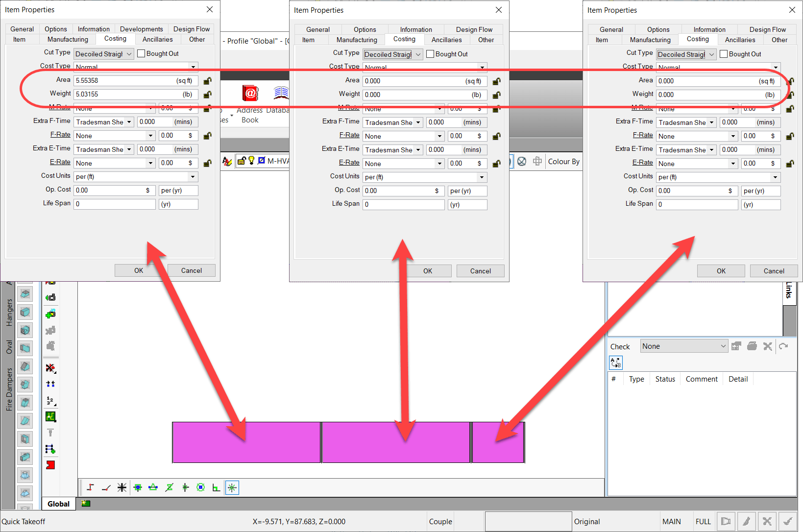
In ESTmep and CAMduct, if you use the 3d View and stretch duct to add pieces, you end up with duct that has zero Area & Weight. This also means you have zero cost for that material.
This is a confirmed issue that’s been around forever. I’ve tested from 2016 thru 2023 and can reproduce in all versions.
Here’s what that looks like…
The Fix
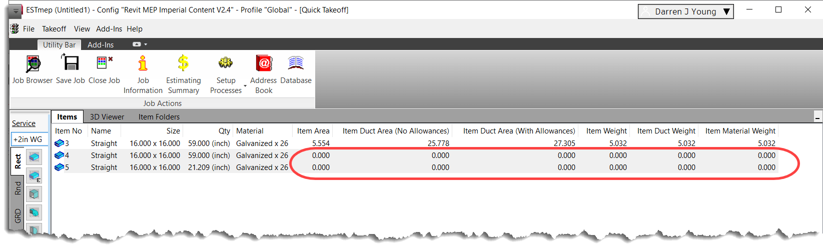
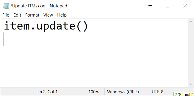
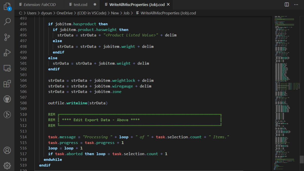
The good news is, there’s a quick fix (workaround) you can deploy to update the weight and area. Using Notepad, you can make a quick COD script that updates the ITM’s. Below is what your script should look like…
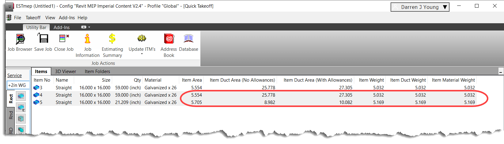
Once you create the COD script, it’s recommended you put it in the SCRIPTS folder of your Fabrication Configuration. From there, you can make a process that calls the script which will update all the ITM’s to their proper Area and Weight. The display on the Item Takeoff may not refresh. If so, just browse to another tab and back. Here’s what that looks like….
So, which this doesn’t “Fix” the issue, it does work around it fairly easily. Just run the process before running and reports or data exports.
If you’ve not downloaded the Autodesk Fabrication Script Libraries lately, you might want to grab an updated copy. There’s been several updates over the last month. Here’s what’s changed…
DamperRotation Property (undocumented) has been added to all Debug, Job and Library scripts. Support for this property was added in 2017 but never documented. It’s there to support the rotation of Dampers on Fabrication Parts in Revit. It should be noted, that this value is Added to the Angle property of the assigned damper. As such, it acts as an Adjust and not an Override. e.g. Damper w/Angle of 90 + Rotation Property in the ITM of 90 results in a damper rotated 180 degrees.
StiffenerGroup Property added to the Autodesk Fabrication 2022.0 and later versions of the Debug, Job and Library scripts.
AirturnGroup Property added to the Autodesk Fabrication 2022.0 and later versions of the Debug, Job and Library scripts.
SplitterGroup Property added to the Autodesk Fabrication 2022.0 and later versions of the Debug, Job and Library scripts.
InsulationStatusLock Property added but listed as “Unavailable” as it stopped working in 2017. Added in the hopes it gets fixed in future versions.
StructureType Property added to the Autodesk Fabrication 2022.0 and later versions of the Debug, Job and Library scripts. Property was “Write Only” in 2021 and prior versions so was unable to display in prior versions.
Product ListHasCustomData Property has been added to all Debug, Job and Library scripts.
Product ListHasFlow Property has been added to all Debug, Job and Library scripts.
ItemPCFSKey Property has been added to all Debug, Job and Library scripts.
ItemCostByLength Property removed from Material Debug scripts (never really belonged there).
If you write COD Scripts for Autodesk Fabrication, take note. There’s now an Extension for Microsoft Visual Studio Code (VS Code) which is Microsoft’s free code editor. If you use Notepad or Notepad++ to edit your code today you may want to consider switching. The COD Extension has some really nice features. Color coding of your code is the most obvious as shown below. However, there’s a lot more than just color coding. Features like Auto-Complete, Folding Sections and Dimension/Option Picker are nice additions in addition to a lot more robust documentation.
Installing The Fabrication COD Extension
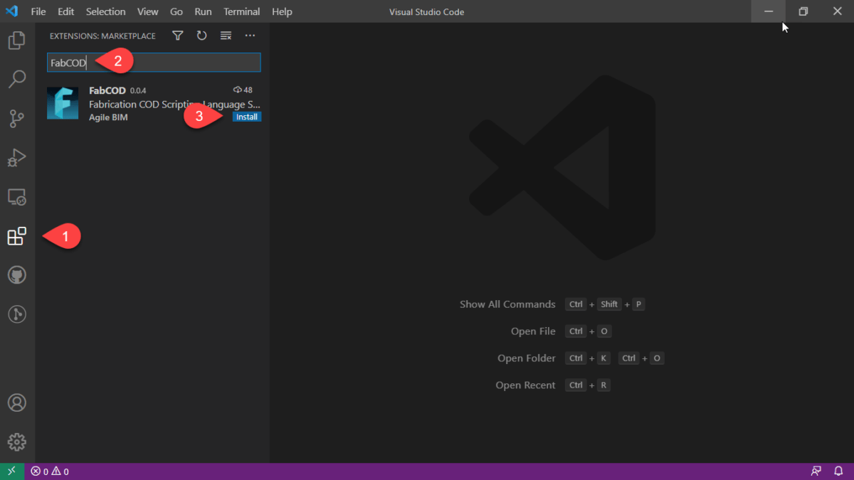
If you don’t already have it, you can download and install VS Code here…https://code.visualstudio.com/. Once installed, go to the Extension section, type FABCOD and click the Install button.
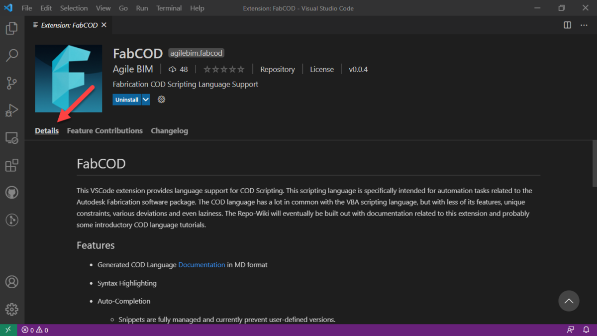
Extension Summary
Once you’ve installed the Extension, you can review a summary of extension details here…
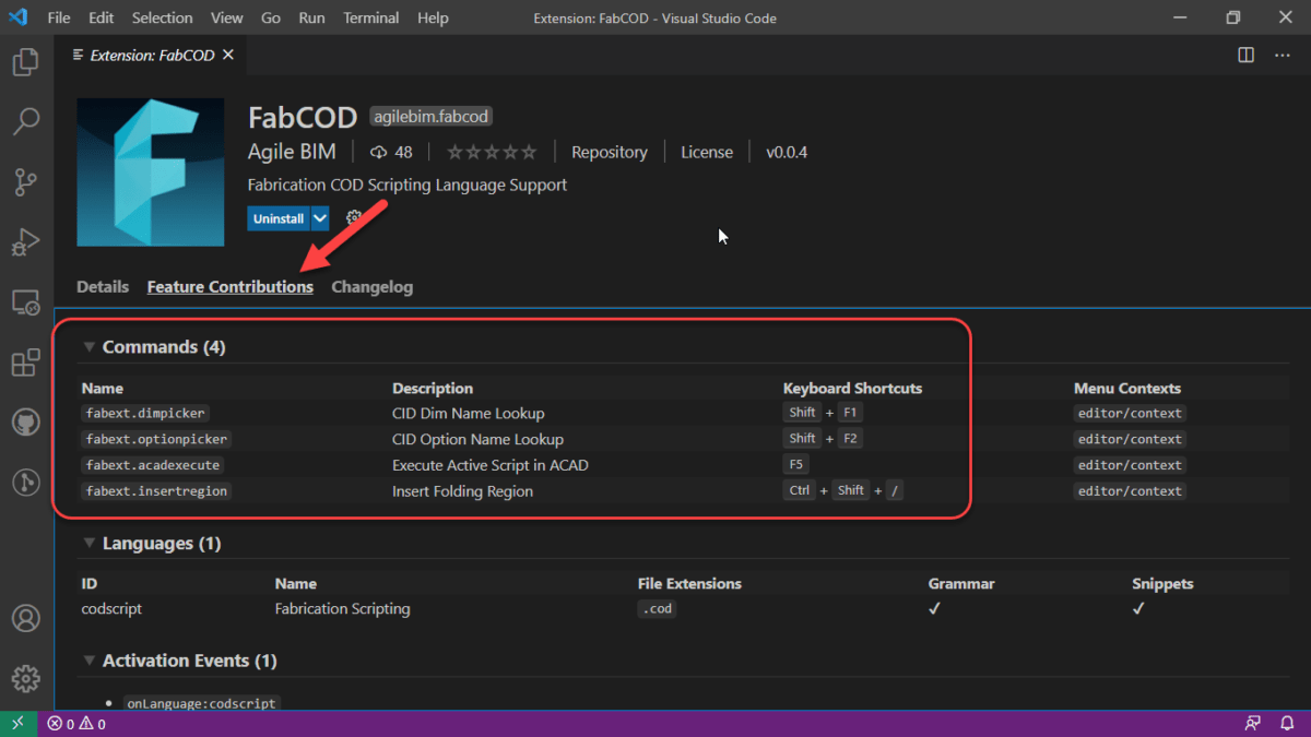
From here, you can review a couple of the key features and their keyboard shortcuts….
VS Code Feature – Mini-Map
Not a feature of the extension, but one reason VS Code is a nice editor is the Mini-Map which helps you visualize where you are your code.
FABCOD Extension Feature – Folding
One of the features the FABCOD extension exposes in VS Code is the ability to collapse/expand sections of code for Looping and Conditional function and other areas. When you move your cursor to the left margin, you see symbols that activate this functionality called Folding.
In addition to Folding sections of code, you can create your own areas of code to collapse/expand. These are Folding Regions and can be inserted (or typed manually using the proper syntax) by highlighting the code and pressing CTRL+SHIFT+/.
FABCOD Extension Feature – AutoComplete
Auto-Complete is another core feature of any code editor. VS Code’s Auto-Complete features is leveraged by the FABCOD extension. You’ll need to be editing a saved file with a COD file extension so the VS Code extension knows which code extension to use.
ABCOD Extension Feature – Hover Tips
If you hover over known functions/properties and their context can be determined, VS Code will display a tooltip for the function you’re hovering over. This can be a great way to learn coding as it’ll help you with the syntax.
FABCOD Extension Feature – DIM / OPTION Picker
One of the best features of the FABCOD extension is the ability to get suggestions for the Dimension (DIM) and Options. You can activate the DIM picker with SHIFT+F1 and the OPTION picker using SHIFT+F2 keyboard shortcuts. When using these features, you are presented with an edit box. You type the CID/Pattern Number you’re interested in and press Enter. You are then given a list of Dimensions or Options you’re interested in. It’s not fool proof because some patterns have variable DIM/OPTION values but it seriously helps none the less. Take a look here…
FABCOD Extension Feature – Additional Help
Sometimes you need added help for a function. The FABCOD extension is an open source project on GitHub (https://github.com/AgileBIM/FabCOD). This project contains added help for every function and property and is Auto-Generated and updated as the extension is developed. You can access this help from any of the popup ToolTips by clicking on the BLUE hyperlinked text.
FABCOD Extension Feature – AutoCAD Launcher
One of the other neat features of the FABCOD extension is the AutoCAD Launcher. Pressing F5 in the editor will initiate the script in CADmep. Simply Alt-Tab to AutoCAD and press enter. AutoCAD and CADmep must be loaded at the time for this to work. Due to Autodesk’s limitations in their API’s, this functionality does not work with ESTmep or CAMduct.
VC Code FABCOD Extension – Wrapup
There’s a lot more to VS Code that I won’t get into here. I’ve only covered the highlights of how it and the FABCOD extension can be used to help edit COD file in Autodesk Fabrication. As it’s an open source project, there’s instructions on how to become involved if you have the coding skills. You can also just head over and log issues or suggestions. (https://github.com/AgileBIM/FabCOD)
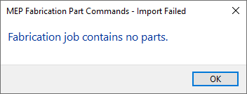
Have you ever tried importing an MAJ into Revit and received the following error….Fabrication Job Contains No Parts.
There’s a lot of reasons this can occur and it’s NEVER because there are no parts. So much for Autodesk’s QA/QC and Error checking.
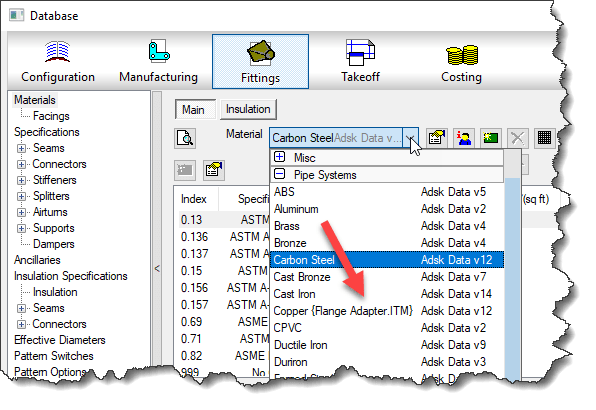
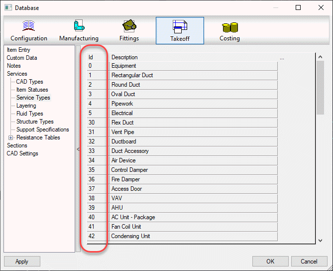
You may see this most commonly because parts used in the model contain data that’s no longer in your database. You’ve likely noticed from time to time database entries with curly braces around parts of the name like the following…
This happens when an entry in the database is used by an ITM but the database entry itself later gets deleted. Information is cached within the ITM so when it’s accessed, it creates a Proxy entry in your database if it was missing. Within the {Curley Braces} is the name of the object that created the entry.
While CADmep, ESTmep and CAMduct handle this fairly gracefully, Revit on the other hand does not. When it attempts to load an MAJ, it sees these entries and notices they’re missing from your database and prohibits you from importing the MAJ file. Revit thinks the database doesn’t match the MAJ and stops you cold!
A Possible Fix
If this is cause for the import error, you can use the following COD script to potentially work around the issue….
Take the following script and run in in CADmep, ESTmep or CAMduct. You should be logged in with Administrative Permissions while doing this. This script isn’t fixing Revit or the MAJ. What it’s doing is loading ALL the ITM’s from your Database Library into memory.
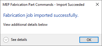
The process of loading all these ITM’s into memory creates all these proxy entries in your database. This way, when Revit attempts to import the MAJ, the data associated with those ITM’s are most likely present in your Database configuration. In many cases then results in a successful import of the MAJ.
If the Revit file you are importing the MAJ into already points to a Fabrication Configuration, you should reloaded the configuration FIRST before attempting to import the MAJ.
If for some reason this process still doesn’t work, verify that Revit is reading from the same database location as the version of CADmep, ESTmep or CAMduct where you ran the COD script.
In the event it still doesn’t work, there may be other reasons for the failure but this is often the most common, especially with MAJ’s created recently.
If it does work, you’ll want to use the other scripts I provide on this site to help analyze your database. You likely deleted those database entries in the first place for a reason. You either didn’t realize they were needed, or you didn’t know where they were used to repoint those ITM’s to a proper substitute. Those scripts can help you find which ITM’s use which database entries.
In the list of COD Scripting updates I just posted, there’s a couple undocumented functions that have been on my list to explore for more than a few years. I’ve finally gotten to them and figured out what they do.
I won’t comment on how long it took me to actually explore what I had listed in my “To Research” list for years other than to say, Procrastination is a Virtue for those with no Patience.
So without further delay…here you go….
Output Function
This first one is the OUTPUT function. You can call it a couple different ways, with and without parenthesis just like the DEBUG function. It doesn’t really seem to matter. It’s really kind of a worthless function in my opinion.
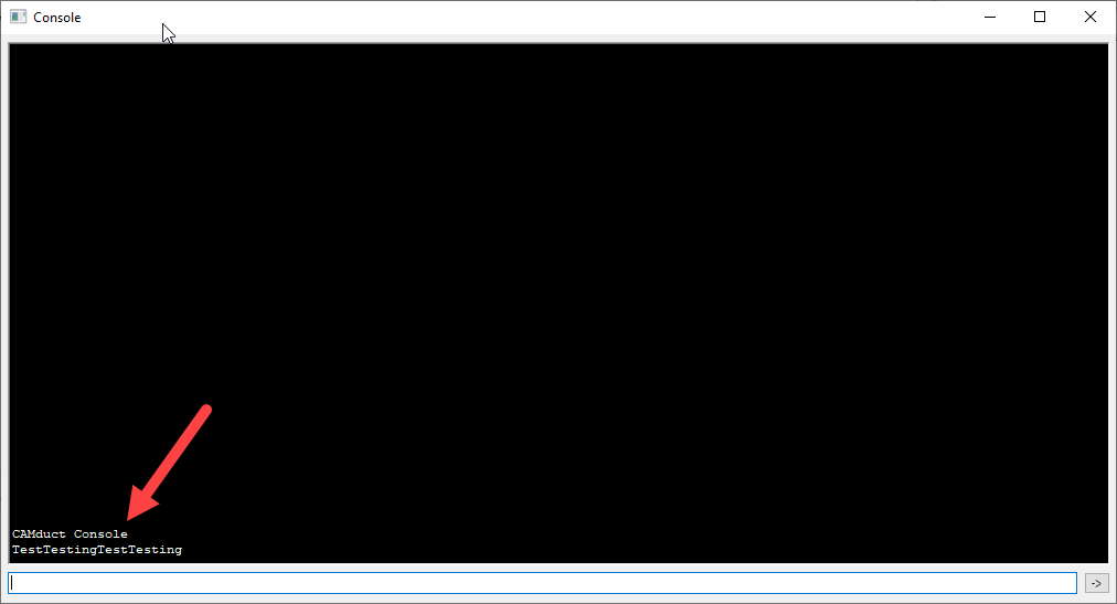
Not only does it only work in CAMduct and ESTmep (not CADmep) it really isn’t that helpful. It just outputs a message to the Console window. I was initially hopeful it would allow me to “script” some of the secret Console command but no such luck. It’s just a message.
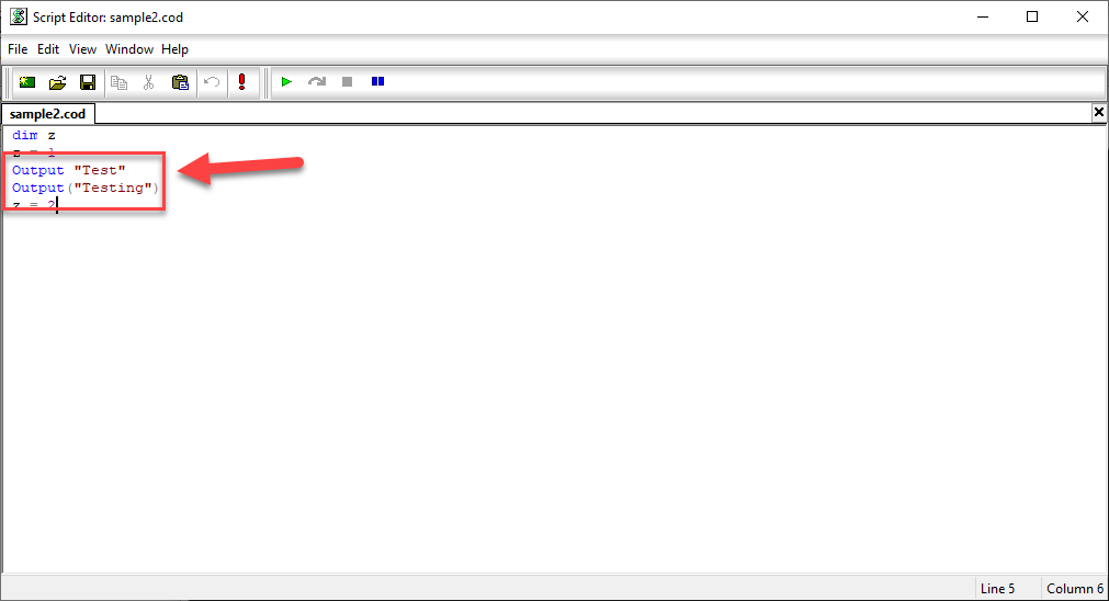
You can see in the COD Code editor the below with both syntax examples…
When you run the script, it’ll call up the Console and display the text you specified. You can see from the following example, it doesn’t even space the text when you call it multiple times. Even tried embedding a Carriage Return in the string and still no luck automating via the Console.
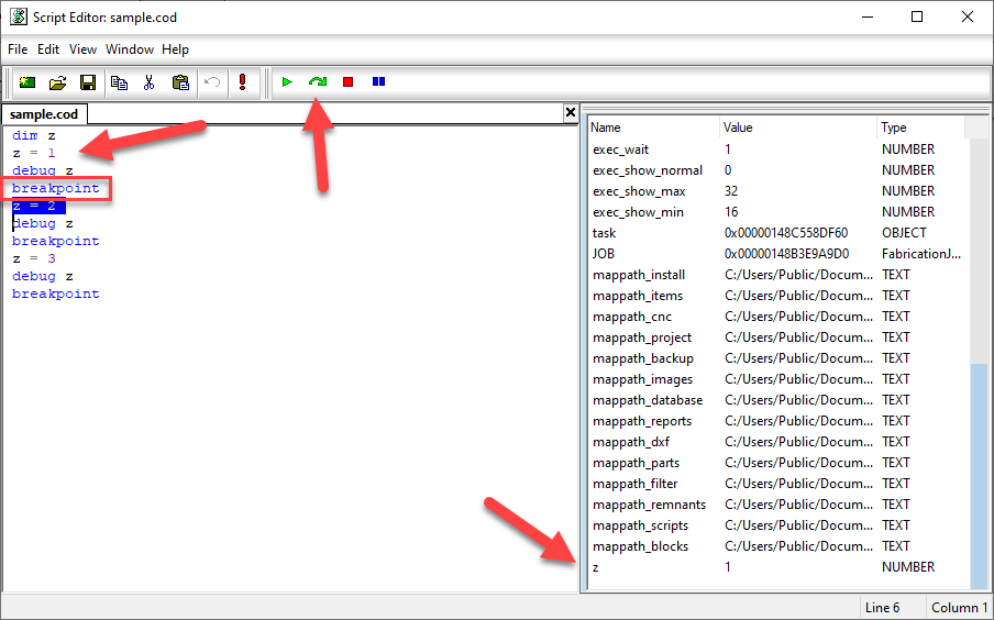
Breakpoint Command
The other command is much more helpful and something most folks don’t know about. I have run into a couple now who knew but most it’s not known. I wish I knew years ago…it’s actually a small step closer to what you’d expect in a modern IDE (Integrated Development Environment).
The Breakpoint function calls up the panel on the right. It displays the values of all your variables. You can see how the value of the “z” variable is displayed. When you hit a Breakpoint, code execution stops until you hit the green arc’d arrow. Code execution then continues until you get to the next Breakpoint if any.
You can access the COD Script editor in CAMduct or ESTmep using the FILE pulldown menu. You can also use the editor in CADmep but unfortunately, there’s no way to display it without writing intentionally wrong code to cause your program to fail and display it. You can then use the editor like you do in ESTmep or CAMduct.
One thing to note, BREAKPOINT only appears to work when you execute code from the Script Editor. If you call it from AutoLISP using (executescript “myscript.cod”) or the EXECUTESCRIPT command in CADmep or by right clicking in your Takeoff items in ESTmep or CAMduct, it runs without stopping your code. This means you can leave the breakpoints in your code and edit/debug via the script editor but not have to remove them when executing them un a production setting.
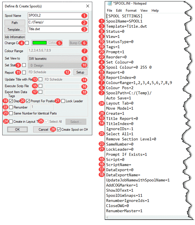
Most (but not all) of the settings in SPOOL.INI relate to the SPOOLDWG command dialog. The following image maps those fields in the dialog with those found in the SPOOL.INI file.
Values and description are listed in the below table along with some additional notes as well as settings related to spooling but not part of the SPOOLDWG dialog.
Ref.
Setting
Value
Description
Note
1
SpoolName
Alpha/Numeric
Name of Spool
3
Template
Path/Template Name
Name or Path & Name of AutoCAD Template for Spool Drawing.
9
Status
0 = Unchecked
1 = Checked
Set Status toggle in Spool Dialog.
8
View
0 = Plan
1 = SW Isometric
2 = SE Isometric
3 = NE Isometric
4 = NW Isometric
5 = None
Sets Spool drawing view type/orientation.
10
StatusType
Status Index Number
Index Number of the Status as defined in your database.
19
Tags
0 = Unchecked
1 = Checked
Set Display toggle in the Spool Dialog.
20
Prompt
0 = Unchecked
1 = Checked
Set Prompt for Position toggle in the Spool Dialog.
22
Reorder
0 = Unchecked
1 = Checked
Set Renumber toggle in the Spool Dialog.
4
Set Colour
0 = Unchecked
1 = Checked
Set Change Colour toggle in the Spool Dialog.
5
Spool Colour
RGB Value
RGB (Red Green Blue) color value of the last spool.
RGB Values are expressed as 3 integers, each between 0 and 255.
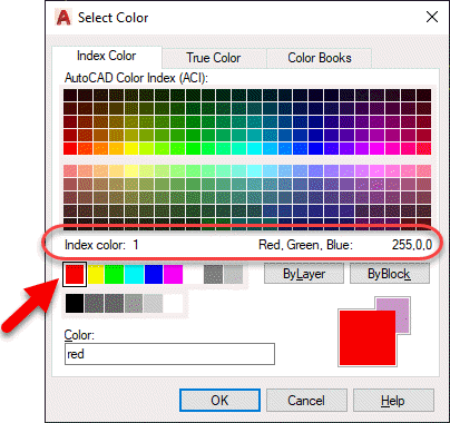
Use AutoCAD DDCOLOR command to determine color numbers & corresponding RGB values.
Note 1
11
Report
0 = Unchecked
1 = Checked
Set Report toggle in the Spool Dialog.
12
ReportIndex
Integer
Zero based index as listed in the drop down list in the Spool Dialog.
e.g. 0 = 1st Report, 1 = second report, etc.
7
ColourRange
Comma separated Integer List
List of Integers separated by commas.
Represent the AutoCAD Color Index numbers (ACI) of the colors to cycle through for spool colors.
Use AutoCAD DDCOLOR command to determine color numbers.
Note 1
6
Colour Pos
Integer
Zero based index of color range for the last color used on a spool.
2
SpoolPath
File Path
Folder where created spool drawings are located.
n/a
Auto Save
0 = No
1 = Yes
If Spooling to separate DWG's instead of Layouts should spool drawings should be saved after they are created.
24
Layout Tab
0 = Unchecked
1 = Checked
Set Create in Layout Tab toggle in the Spool Dialog.
n/a
Move Model
0 = No
1 = Yes
Sets if the spool be moved to 0,0,0 when creating the spool DWG's.
26
Create
0 = Unchecked
1 = Checked
Set Create Spool on OK toggle in the Spool Dialog.
13
Title Report
0 = Unchecked
1 = Checked
Set Update Title with Report toggle in the Spool Dialog.
14
TitleIndex
Integer
Zero based index as listed in the drop down list in the Spool Dialog.
e.g. 0 = 1st Report, 1 = second report, etc.
n/a
IgnoreIDs
Comma separated Integer List
List of Integers separated by commas. Integers represent the Service Type Index.
Items with these Service Type Indices will not be renumbered or have their item number displayed in the Spool. (Exception: See RenumberIgnoreIds setting)
Note 2
25
Select All
0 = Unchecked
1 = Checked
Set Select All toggle in the Spool Dialog.
n/a
Remove Section Level
0 = No
1 = Yes
Controls moving the Spool to 0,0 (X,Y) if 1/Yes or 0,0,0 (X,Y,Z) if 0/No when the Move Modelsetting is set set to 1.
23
SameNumber
0 = Unchecked
1 = Checked
Set Same Number for Identical Parts toggle in the Spool Dialog.
21
LockLeader
0 = Unchecked
1 = Checked
Set Lock Leader toggle in the Spool Dialog.
n/a
Prompt If Exists
0 = No
1 = Yes
Prompts to overwrite existing Spool DWG if it already exists.
15
Script
0 = Unchecked
1 = Checked
Set Execute Script File toggle in the Spool Dialog.
16
ScriptName
COD Script File Name
Name of COD Script File to execute on the spool.
Script name should be the file name only and NOT include the ".COD" extension.
Script file must exist in the folder specified by SCRIPTS section of MAP.INI.
Note 3
17
DataExport
0 = Unchecked
1 = Checked
Set Export Item Data toggle in the Spool Dialog.
18
DataExportName
IEX Report File Name
Name of IEX Data Export Report to run on the spool.
Report name should be the file name only and NOT include the ".IEX" extension.
Reports must exist in the proper product specific sub-folder under the reports folder specified by REPORTS section of MAP.INI.
Note 4
n/a
UpdateJobNamewithSpoolName
0 = No
1 = Yes
Updates the MAJ Job Name (Job Info) with the spool name prior to running any exports or reports.
n/a
AddCOGMarker
0 = No
1 = Yes
Calculates the Center of Gravity (COG) and inserts the COG Block (with attribute(s)) for the spool.
n/a
Show3DText
0 = No
1 = Yes
If showing annotations and the view is a 3d view, ensures that the database option is enabled to display in 3d.
Note 5
n/a
SpoolDimSnaps
Integer
Enumeration (Bitwise) value for which OBject Snap Modes are set when using the SPOOLDWG command.
Note 6
n/a
RenumberIgnoreIds
0 = No
1 = Yes
Renumbers the list of Ignored parts specified in the IgnoreIDs setting and stores the setting in the Alias field.
If the Alias already contains a value, the number will be appended to the value as a suffix.
n/a
CloseDWG
0 = No
1 = Yes
When spooling to separate DWG's instead of Layouts, will close the DWG after creation.
n/a
RenumberMaster
0 = No
1 = Yes
If renumbering, apply the new numbers to the Master DWG.
Note 1:
The DDCOLOR Command in AutoCAD can be used to determine ACI (AutoCAD Color Index) and/or RGB (Red Green Blue) values.
Note 2
Service Types can be found in the database editor. Use the Index Numbers in the Spool.ini settings.
Note 3
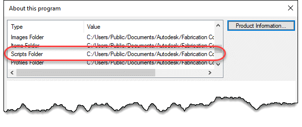
COD Scripts must be located in the folder specified by the MAP.INI file.
Type the command APPINFO in CADmep to display a dialog which will show where the Scripts should be located.
Note 4
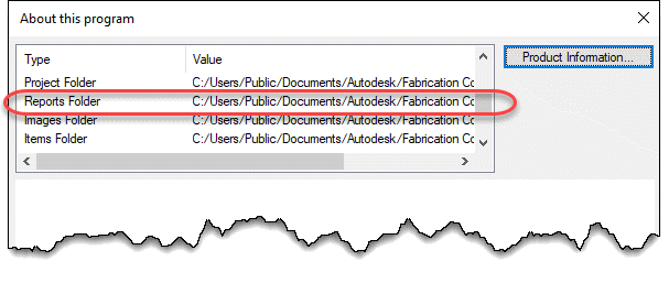
IEX Data Export reports must be located in the software specific folder specified by the MAP.INI file. MAP.INI specifies the root folder for reports which are then found in a subfolder named based on the product using the reports. This makes knowing the exact reports folder a little difficult when looking in the MAP.INI file.
Tp more easily find the exact report folder, type the command APPINFO in CADmep to display a dialog which will show where the Scripts should be located.
Note 5
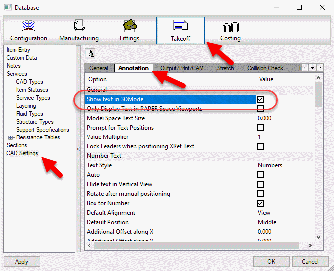
The database setting this option controls can be found in the database editor under Takeoff -> CAD Settings -> Annotation.
Note 6
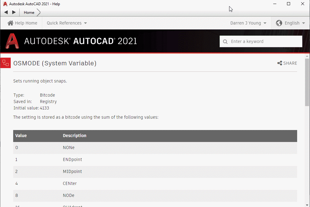
To understand how bitcoded values work for the Snap modes, look up the OSMODE system variable in AutoCAD’s Help system.
I’ve made a couple updates to the Autodesk Fabrication script libraries. If you use them, you can download updated versions from here.
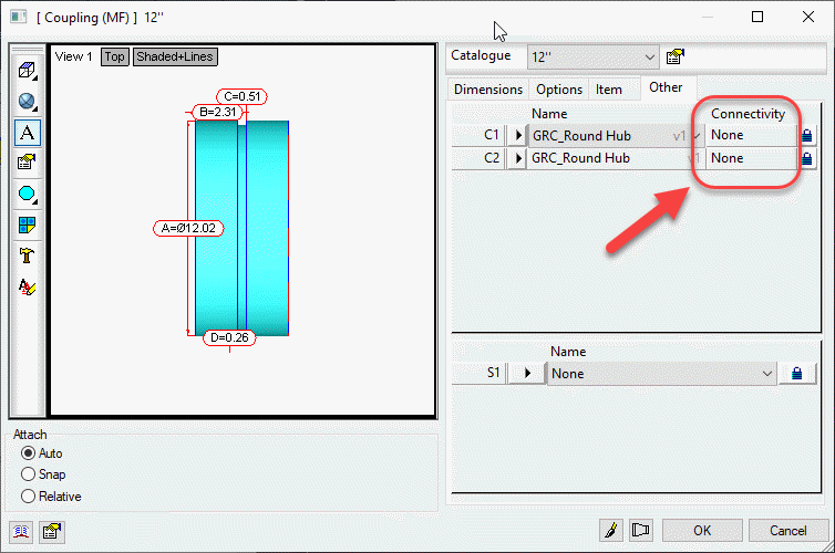
Scripts have been updated to include the Connector Material property found on CID/Patterns 522, 1522 & 2512 as shown below…
This property is intended to be used by a connector to specify a alternate material the connector can connect to. This allows a coupling to connect to alternate materials such as with transition couplings.
I have updated the Autodesk Fabrication COD Scripting resources. Resources have also been reorganized. Everything is still there but you may have to navigate to it differently.
Most of the updates are additions to the COD Scripting reference. They now include all the information that was in my Advanced Scripting sessions at MEP Force and Autodesk University.
A complete list of all COD Scripting resources can be found here. The COD Language reference is a complete list of all properties, functions, operators, keywords, and anything else scripting that I’m aware of. Everything I know about COD Scripting both documented and undocumented is located here. If you notice properties or functions in COD scripts of yours or from others that is not listed here, please let me know. I’d love to add anything new you find.