CADmep, ESTmep and CAMduct all use the concept of an Attacher. This is what tells Fabrication which way to route elbows and branches.
Most people know how to place and rotate the Attacher. There are a few other tricks to working with the Attacher that you may not know about.
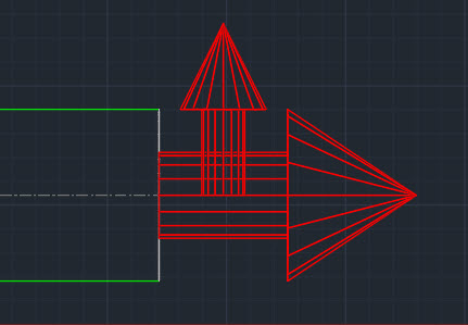
Up or Down, How to Get Around
Depending on your view orientation, you may notice part of the Attacher turns from Red to Blue or Green. As you rotate the Attacher it’s color will change to indicate the direction the arrow is pointing.
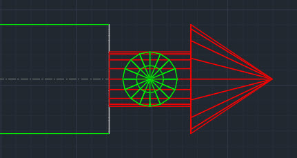
Green = Grass (Attacher is pointing away from you)
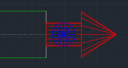
Blue = Sky (Attacher is pointing toward you)
Rotation Tricks
Depending oh which program you’re in (CADmep, ESTmep or CAMduct) and the keys you press, the Attacher rotates differently. Here’s a chart explaining those nuances.
Rotation
Method
CADmep
ESTmep
CAMduct
90 Degrees CCW
Click
Yes
Yes
Yes
90 Degrees CW
Shift+Click
No
Yes
Yes
180 Degrees (Flip)
Ctrl+Click
Yes
Yes
Yes
15 Degrees CCW
Alt+Click
Yes
No
No
CADmep – Click Attacher to Rotate Counter Clockwise 90 DegreesCADmep – Ctrl+Click Attacher to Rotate 180 Degrees (Flip)CADmep – Alt+Click Attacher yo Rotate Counter Clockwise 15 DegreesESTmep / CAMduct – Click Attacher to Rotate Counter Clockwise 90 DegreesESTmep / CAMduct – Shift+Click Attacher to Rotate Clockwise 90 DegreesESTmep / CAMduct – Ctrl+Click to Rotate Attacher 180 Degrees (Flip)
Warning: This is last part (4 of a 4) in a series on merging Autodesk Fabrication Databases. Autodesk Fabrication software is extremely powerful and flexible but that also makes it very fragile. Use the below guidance with caution. I highly recommend backing up your configuration before attempting anything I’ve recommended. It never hurts to have a firm grasp of how Autodesk Fabrication functions from an administrative perspective. Consider yourself warned!
Method 4: MERGEDB (CAMduct only)
This last method is very quick and powerful but only available in CAMduct. If you’re not a CAMduct user, simply download and install to perform this process while in the 30-day trail period.
This method doesn’t let you pick and choose individual database entries but you can pick certain database types and quickly merge all of them into a new configuration. Unlike prior methods were you typically started in the old Database to export an *.IOX / *.IEZ file or create a Proxy ITM first, in this process, you start with the database you want the items to be imported into.
In addition to make of the database entries Method 1 supported, this method also supports these additional entries.
Cutouts
Leads
Rates
Facings
Materials
Silencers
Hanger Specifications
Notches
Vanes
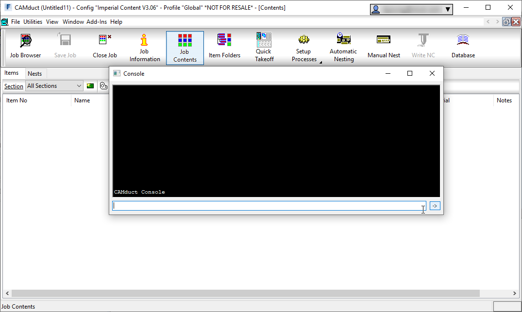
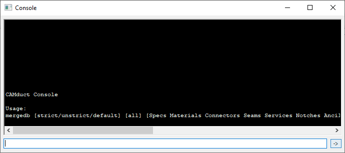
To use this method, start CAMduct and type CTRL-SHIFT-C to display the command window as shown below.
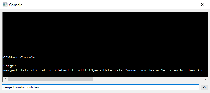
From the command window, type MERGEDB and press <Enter>. This doesn’t do anything other than tell you the data the command needs as shown below. The Strict/Unstrict options tell the merge process if it should only look at the name or the data to determine if it’s duplicate. If you choose strict and the items are already in your database, something as simple as 3 vs 4 digits after a decimal will cause a duplicate entry. In most cases, unstrict is all that’s required.
For this example, we’ll type MERGEDB UNSTRICT NOTCHES to import all the notches from one database to another as shown below.
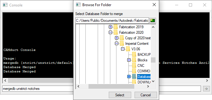
When you press enter, you’re prompted to select a folder. You should select the Database folder of the old database you want to merge into your current database.
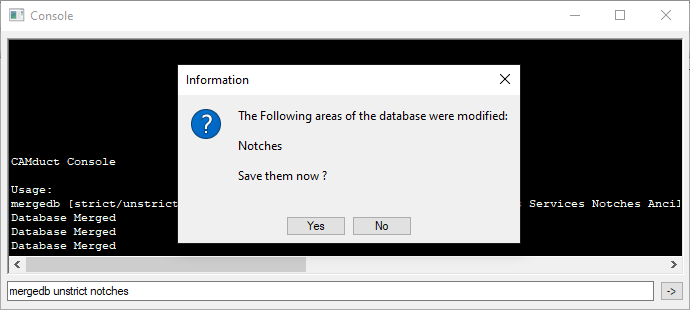
If new items are found, you’ll be notified and prompted if you want to save the changes or not.
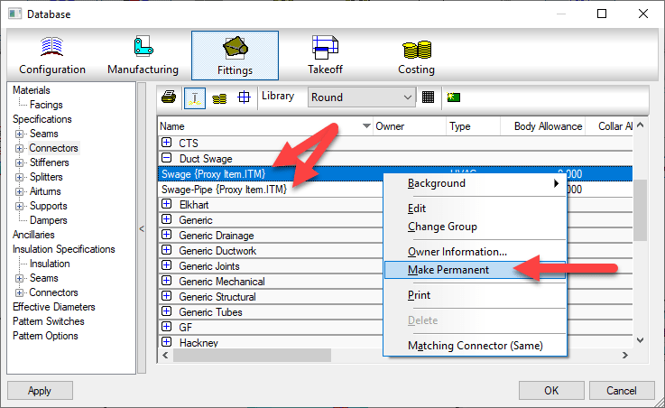
Upon completion of the merge, you’ll need to go to those items in your database and make permanent any you intend to keep and remove those you didn’t want.
Pros: > Only way to import some database entry type. > Easiest way to merge the bulk of 2 database together. > Extremely fast and efficient. Cons: > Requires CAMduct. > Can not pick and choose database entries, only database types. > Requires post merge cleanup of deletion or making entries permanent
Warning: This is Part 3 of a 4 part series on merging Autodesk Fabrication Databases. Autodesk Fabrication software is extremely powerful and flexible but that also makes it very fragile. Use the below guidance with caution. I highly recommend backing up your configuration before attempting anything I’ve recommended. It never hurts to have a firm grasp of how Autodesk Fabrication functions from an administrative perspective. Consider yourself warned!
Method 3: Service Export/Import
This method is very similar to Method 2 above except that it works on a full service and all the items within it’s service template. If you have an existing service you want to post from one Database to another, this is a great method. Even if you just have a library of multiple ITM’s, it’s very common to create a transport service. That service holds those ITM’s and can be used as a means to get ITM’s from one database to another. Here are the steps.
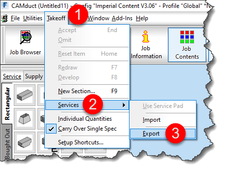
From CADmep, type EXPORTSYS at the command line or in ESTmep or CAMduct, while in the Takeoff screen, select Takeoff -> Services -> Export as shown below…
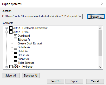
This displays the Export Systems dialog. Use the Browse button to select the location and name of the *.IEZ export file. Select the service(s) you wish to export and click the Export button.
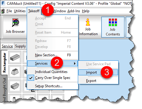
Importing is a similar process. Type IMPORTSYS from CADmep or from the Takeoff screen in ESTmep or CAMduct, select Takeoff -> Services -> Import as shown below…
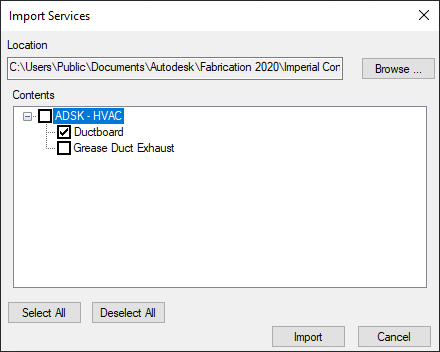
You are prompted to select an *.IEZ file for import. The file will be read and display all the services that were exported. Select those you want to import and click Import.
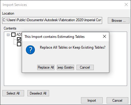
Because IEZ imports can contain a lot of data, it’s likely you may have a lot of duplicates. Upon import, you are prompted if you’d like to Import ALL or NEWER item. Select as appropriate for your situation as shown below.
If Estimating data is found, you are also prompted to Replace or Keep existing tables. Because the database you are importing to is likely your current desired database, I’d recommend to Keep existing tables and only Replace if you intend to bring over labor and cost data in the Import. Once again, choose the option that best suits your needs as shown below.
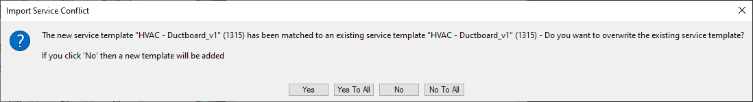
Like in Method 1 earlier, if the import finds a service or template it thinks is the same, it’ll prompt you how to proceed. I highly recommend NOT selecting the “….To All” options as it’s common for the database index to cause false matches and mislead you.
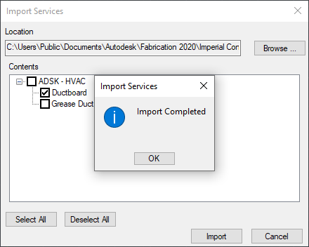
You are prompted once the import is complete. As with Method 2, if ITM’s imported through this process contain new database entries, you’ll need to find those and make them permanent in a similar way.
Pros: > Easiest way to import large numbers if ITM’s and their related database entries. > Easy way to import Services and Service Templates Cons: > Slowest of all process do to all the verification the Import process needs to do. > Can Import a lot more data than you intend. > Can not pick and choose individual database entries to import
Stay tuned for Method 4 in my next and last post in this series.
Warning: This is Part 2 of a 4 part series on merging Autodesk Fabrication Databases. Autodesk Fabrication software is extremely powerful and flexible but that also makes it very fragile. Use the below guidance with caution. I highly recommend backing up your configuration before attempting anything I’ve recommended. It never hurts to have a firm grasp of how Autodesk Fabrication functions from an administrative perspective. Consider yourself warned!
Method 2: ITM’s as Proxy
Another method of transferring data from one database to another is by using ITM’s. Simpy take an existing ITM or make a new one and set some of it’s properties to those you want to transfer. After you’ve completed this, copy the ITM to your desired database.
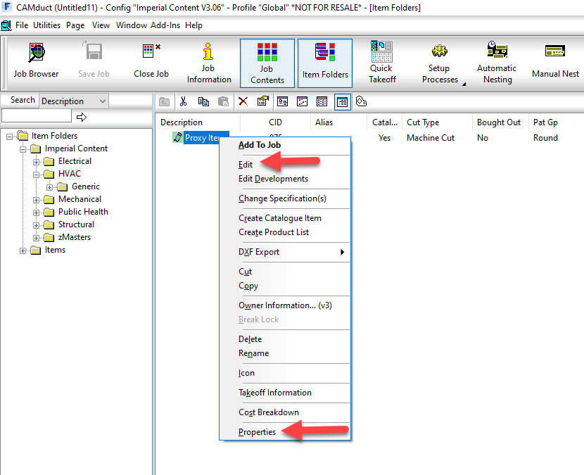
In your desired database, right-click on the newly copied ITM from the Folders view and select Edit or Properties as shown below.
Once the Edit Item or Item Properties dialogs are displayed, you can simply close them. The only purpose in calling them up was to force Fabrication to read all of their settings which in turn causes them to be created as Proxy entries in your database if they don’t already exist.
Once the database entries are in your new database, you’ll want to navigate to those database entries and make the proxy items permanent as shown below.
Pros: > Every property an ITM uses is supported. > Dependent database entries supported (e.g. Fixings on a Support) Cons: > Can bring in more properties than you want which need to be cleaned. > Time consuming for large property sets as multiple ITM’s required. > Proxy items must be manually made permanent afterward
Warning: This is Part 1 of a 4 part series on merging Autodesk Fabrication Databases. Autodesk Fabrication software is extremely powerful and flexible but that also makes it very fragile. Use the below guidance with caution. I highly recommend backing up your configuration before attempting anything I’ve recommended. It never hurts to have a firm grasp of how Autodesk Fabrication functions from an administrative perspective. Consider yourself warned!
Preface
You shouldn’t find yourself merging parts of different Fabrication databases very often. If you do, you may want to revisit your database management workflow and practices.
However there are a number of legitimate reasons you may do it. Most common is the database you’re using now isn’t the one you used a few years ago because you started over. It’s common for a Fabrication database to be a mess. They’re hard to learn and understand and while you learn, you do a little damage unknowingly. Maybe it’s turnover of the staff managing your configuration. Each new person will say they know how to manage Fabrication and what you’re doing is wrong. So they fix it. In the end, you end up with a mix of database management “Styles”.
And last but not least, it’s because trades men and women manage your data. Don’t get me wrong. Your trade staff are hands down the most qualified to manage an Autodesk Fabrication configuration. This is why the task gets assigned to them. But ultimately, what do companies “want” them to do? Detailing and modeling….run piping, plumbing, sheet metal, electrical, etc. Management more often than not pushes them to get back to modeling because management really doesn’t understand the importance of a good database. This leads to shortcuts and mismanagement through no fault of those doing the work. They’re doing the best they can given the constraints their under.
Whatever the reason, if you need to merge parts of different Fabrication Database configurations together, I’ll explain four different methods in the coming posts.
Method 1: Importing / Exporting Database Items
Export/Import Database is the most commonly used method. It’s also the most widely know. In 2014 and earlier versions, many of these were separate commands for each part of the database. In the 2015 version, they were wrapped up in a single command. This process allows you to export and import the following items…
Airturns
Insulation Specifications
Splitters
Ancillaries (except Kits)
Installation Times
Stiffeners
Connectors
Seams
Supplier Costs
Dampers
Sections
Supports
Fabrication Times
Specifications
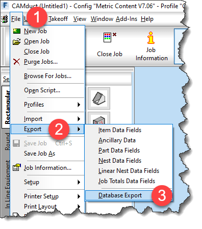
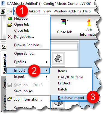
To initiate the Export process, type DBEXPORT at the command line in CADmep. In CAMduct or ESTmep, select File -> Export -> Database Export from the menu as shown below…
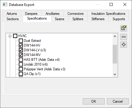
Once you start the command the Database Export dialog is displayed. You can switch tabs and select various database entries to export.
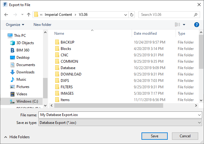
Once you’ve selected the items you wish to export, click OK and save the export file.
This *.IOX file contains everything you selected for export. You can then use this file to import those settings into another database configuration. The process for importing is very similar. Type DBIMPORT at the command line in CADmep or pick File -> Import -> Database Import in ESTmep or CAMduct from the menu shown below…
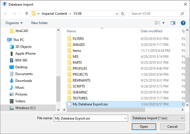
Upon initiating the command, you’re prompted to select an *.IOX file for import. Select the file you wish to import and click OK.
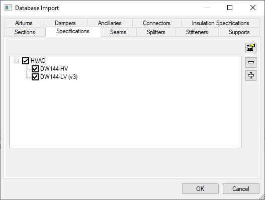
After selecting the file, you are presented with a dialog just like the Export dialog. In this one, you can navigate the various tabs and select what you would like to import.
There is no good way to see what’s available for import without checking all of the tabs. Only items included for export will be displayed. You can pick and choose to import some or all of the items that were in the export file.
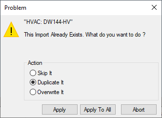
If an item you are importing already exists, you can choose to Skip, Duplicate or Overwrite the item. A word of caution, if your configuration has not been managed well, be very careful selecting the Apply to All button. There are times when the items Fabrication thinks are duplicate are indeed different items. This can be due to database corruption or misaligned indexes or any number of other reasons. If you’re concerned, select Apply for each item one at a time to verify the duplicates aren’t unexpected.
Pros: > Easy to use > Most common items supported > Dependent items (e.g. Ancillaries attached to a Support) are included even though they are not displayed. Cons: > Not all database areas supported (e.g. Materials, Ancillary Kits, Notches, etc.)
Autodesk has released update 2020.1 for Autodesk Fabrication products CADmep, CAMduct and ESTmep. You can see the small token list of fixes here.
Really not much in the way of fixing the many legacy, multi-release defects that have been piling up. Still no word on the update to plug the security hole in Revit where you’re COST/LABOR data can be mined by others.
One thing to note about this release, it’s not an “Update” that patches your existing system. The Update requires a full install. That means that 2020 versions of CADmep, ESTmep, CAMduct as well as Tracker, CAMduct Components and Remote Entry need to be removed first.
I would NOT recommend installing the update from the Autodesk Desktop App. I’ve tested on multiple systems both personal and corporate and it gets hung indefinitely on the uninstall of the 2020 versions.
If you do want to install the update, I highly recommend uninstalling yourself before adding the 2020.1 versions. Even manual uninstalls of 2020 have been hit or miss. If they hang, they’re usually already uninstalled and using Task Manager to cancel the running MSIEXEC tasks is enough to finish the uninstalls. Best of luck!
Any sheet metal shop that CNC cuts their liner has likely configured their database to make seam adjustments in the liner developments. These settings are typically global and tell CAMduct to remove the Liner thickness from the Male or Female part of the development.
Another common setting is the compression adjustment in the Insulation Materials. These are all fairly common and self explanatory for most people looking to configure these settings.
Length Adjustments on Radius Elbows
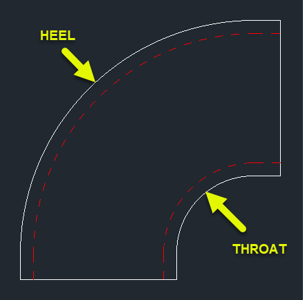
What’s a little less obvious is how to adjust the throat and heel lengths on a radius elbow. If the liner is developed based on metal size, the throat is typically too short and the heel a little long. This is due to the bending allowance of thicker materials. While acoustic liner has a little give but when using something like armorflex for liner, it’s a little more rigid and these lengths can cause issues.
To better understand the Throat and Heel of a radius elbow, we can look at the Top view (cheek). The following image shows the Throat and Heel pointed to with arrows. You’re looking at these parts on their edge.
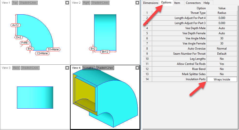
Prepare Your Fittings
To configure the calculation used for the liner on these parts, you first need to change an option on your ITM. The following image is for a radius elbow (CID 4). Here you’ll want to change the “Insulation Parts” Option to “Wraps Inside“. If you leave this set to the default “Same”, the adjustments made later will have no effect.
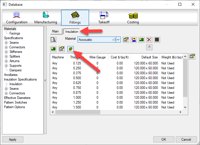
Configure Material Adjustments
To make adjustments to the liner calculation, you’ll go to the Insulation Materials and click the “Insulation Developments” button.
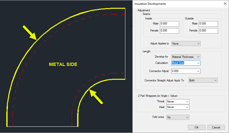
This will bring up a dialog where you can make changes to how the liner gets developed on the throats and heels. The various settings are as follows…
Metal Side
Throat & Heel Liner Developed to the same length as the metal fitting.
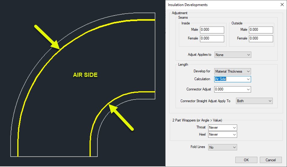
Air Side
Throat & Heel Lengths Developed Based on the AIR side of the liner thickness.
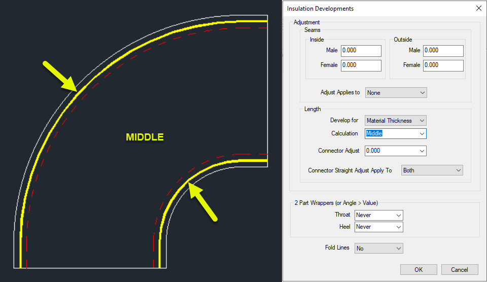
Middle
Throat & Heel length developed based on the middle of the liner thickness.
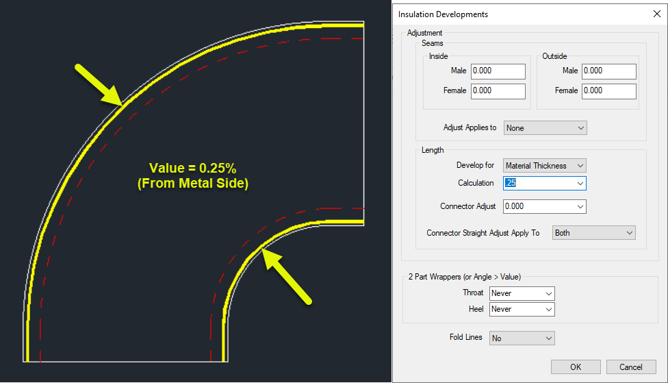
Value (Between 0.0 and 1.0)
Value is between 0 and 1 as a percentage of the liner thickness calculated from the metal side.
0 = Same as “Metal Side” 0.5 = Same as “Middle” 1.0 = Same as “Air Side”
Not All Fittings Supported
Not all fittings support the “Insulation Parts” option. You can run one of the Library export scripts that dumps all the OPTIONS to a CSV file and sort in Excel to look for the CID’s in your library that support “Insulation Parts”. Scripts can be found here.
Not only is DOS still relevant, its often one of the quickest ways to get some things done.
On XtraCAD.com, someone recently asked how to get the system Date and Time in an Autodesk Fabrication COD script. I provided a solution that uses DOS commands inside a COD script. That solution is explained in more detail here.
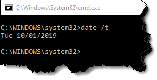
DOS’s “Date” Command
Using DOS, we can use the “DATE” command with the “/T” Switch to output the current date to a DOS prompt.
The information given by this simple command is all we need. A script can easily read the data if the output is redirected to a data file.
We’ll get a little more ambitious and get particular on the formatting. We’ll remove the “Tue” and format the date in the format “yyyy.mm.dd”.
To do this, we can use the “FOR” command in DOS.
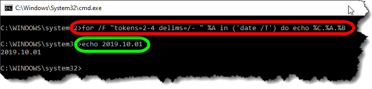
for /F "tokens=2-4 delims=/- " %A in ('date /T') do echo %C.%A.%B
The Red circled area is the command. It takes the data from the Date command and breaks it apart by the delimiters (DELIMS) which is spaces ( ), forward slashes (/) and dashes (-). You’ll note that the Date doesn’t actually contain any dashes so it’s just ignored.
The TOKENS specifies we want the 2nd thru 4th items of data. They will be assigned sequentially to variables starting with “%A”. The Green circled area is the resulting output ECHO’d to the DOS Window in the format we want.
%A = 2nd piece of data (month)
%B = 3rd piece of data (day)
%C = 4th piece of data (year)
Sending Data to a File
Now that have our DOS command, the next step is to send the output to a file on disk. Doing this will allow the COD script to read it back later.
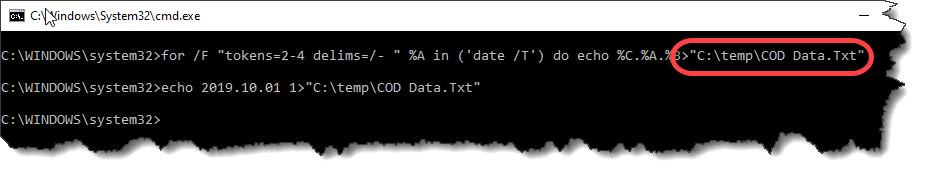
For this purpose, we use a re-director to pump the data to a file. We simply append a suffix like this…
for /F "tokens=2-4 delims=/- " %A in ('date /T') do echo %C.%A.%B>"C:\Temp\COD Data.Txt"
A few notes about redirecting data to a file….
We use double quotes around the file path and name in case it contains spaces. This way, DOS doesn’t interpret the space as a separator between commands.
The Greater-Than (>) symbol is used to redirect output to a file. If the file already exists, it will be overwritten.
Double Greater-Than (>>) symbols can be used to “append” to the end of an existing file. This is handy if you want to add more data to the same file. If the file doesn’t already exist, it will be created.
We Have DOS, Now for the COD Script
Now that we have our DOS syntax down, we can start writing out COD Script. To start, I typically generate a few variables that help me format things.
REM ------------------------------
REM DQ = Double Quote Character
REM CR = Carriage Return Character
REM ST = Single Tab Character
REM WF = Working File
REM ------------------------------

DIM DQ = ascii(34)
DIM CR = ascii(10)
DIM ST = ascii(9)
DIM WF = "C:\Temp\COD Data.Txt"
Because some of our syntax contains double quotes, and because strings (text) in a COD script also contain double quotes, having multiple double quotes in a row can be confusing. Additionally, sometimes the script has trouble understanding where one string ends vs what’s a string containing a double quote.
To handle this, I set a variable (DQ) that will represent any double quote within a COD Script string. I also use a Carriage Return (CR) variable and a Single Tab (ST) variable for formatting purposes that you’ll see later.
Lastly, I also set a variable for the data file. It’s at the beginning, it’s easy to find and change without having to get in the middle of a lot of confusing formatted string data later.
Executing DOS From the Script
To execute an external command from a script, we can use the EXEC function.
<command> = “CMD.EXE” This is the DOS Command Interpreter
<execution mode> = exec_wait + exec_show_min These are a couple variables that tell the external program to “Wait” until finished before proceeding with the rest of the script and to minimize the Window.
<command/arguments> = The Prior DOS Syntax (with modifications) goes here.
The CMD.EXE program takes an argument of “/C” followed by the command it’s going to execute which is our DOS Syntax. Pay close attention, because here’s where we’re going to have to break up the DOS commands and embed our variables for the embedded double quotes.
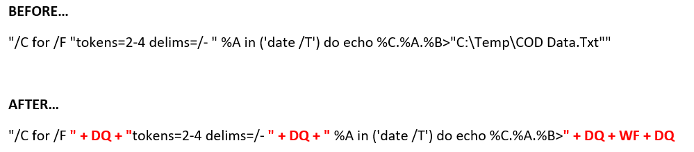
The below is a single “String” with double quotes on each end. It also has a lot of double quotes inside the text which will confuse you and your script. This below syntax is WRONG and needs to be corrected….
"/C for /F "tokens=2-4 delims=/- " %A in ('date /T') do echo %C.%A.%B>"C:\Temp\COD Data.Txt""
To do this, it’s easier to illustrate in color. We’re going to take one very long complicated string, and break it into several smaller strings when there’s double quotes within the string.
That is, where ever there’s a double quote within the string, we’re going to make a smaller string before and after, and piece them back together and use our DQ variable to embed the double quote between them.
This works for the first two double quotes. But at the end of the string, we’re going to do something a little different. Here, we want to remove file name and use the WF variable we set earlier to store the file name. And because the filename may have a path, we surround it with DQ variables to embed it in double quotes.
The next piece of code should look like this when we’re done. This will run our DOS command and dump the date to a file,
REM ---------------------
REM Get Date (yyyy.mm.dd)
REM ---------------------

Exec("cmd.exe", exec_wait + exec_show_min, "/C for /F " + DQ + "tokens=2-4 delims=/- " + DQ + " %A in ('date /T') do echo %C.%A.%B>" + DQ + WF + DQ
Reading Our Data File
Now that we’ve dumped the data file to disk, we can read it back in from the COD script using the following code…
DIM myDate
Object myFile as File (WF, forinput+istext)
myDate = myFile.Readline()
myFile.Close()
This code opens the file and reads its data and saves it to a variable. You’ll also note that this code doesn’t add extra double quotes around the WF “Working File” variable. That’s because they aren’t needed here, and will in fact cause problems. The COD Script language is actually better at handling files with and without spaces because it uses a comma (,) as it’s data separator between the file name and file read modes.
Displaying Our Data
Last, we can display the data in a simple debug dialog. Here, you’ll see I make use of the ST variable to place a single tab between the data purely for formatting purposes.
Debug "Date:" + ST + myDate
The Bigger Picture
The following code takes all the above principals and goes a little further. With everything you’ve learned, you should be able to figure out what it’s doing and how. It’s doing all the same things plus a little extra…
Also writing TIME and the USERNAME of the currently logged in Windows User to the data file.
It’s “Appending” the TIME and USERNAME using “>>” instead of “>” that DATE uses.
It’s reading 3 lines of our data file
The data file is deleted after it’s read leaving our system clean of temporary files.
The data is displayed by also using the CR (Carriage Return) variable to start new lines for the additional pieces of data.
REM ------------------------------
REM DQ = Double Quote Character
REM CR = Carriage Return Character
REM ST = Single Tab Character
REM WF = Working File
REM ------------------------------

DIM DQ = ascii(34)
DIM CR = ascii(10)
DIM ST = ascii(9)
DIM WF = "C:\Temp\COD Data.Txt"

REM ---------------------
REM Get Date (yyyy.mm.dd)
REM Get Time (hh:mm)
REM Get User (login name)
REM ---------------------

Exec("cmd.exe", exec_wait + exec_show_min, "/C for /F " + DQ + "tokens=2-4 delims=/- " + DQ + " %A in ('date /T') do echo %C.%A.%B>" + DQ + WF + DQ)
Exec("cmd.exe", exec_wait + exec_show_min, "/C for /F " + DQ + "tokens=1-2 delims=: " + DQ + " %A in ('time /T') do echo %A:%B>>" + DQ + WF + DQ)
Exec("cmd.exe", exec_wait + exec_show_min, "/C echo %username%>>" + DQ + WF + DQ)

REM ---------
REM Read Data
REM ---------

DIM myDate
DIM myTime
DIM myUser

Object myFile as File (WF, forinput+istext)

myDate = myFile.Readline()
myTime = myFile.Readline()
myUser = myFile.Readline()
myFile.Close()

REM ----------------
REM Delete Data File
REM ----------------
Exec("cmd.exe", exec_default + exec_show_min, "/C DEL " + DQ + WF + DQ)

REM ------------
REM Display Data
REM ------------

Debug "Date:" + ST + myDate + CR + "Time:" + ST + mytime + CR + "User:" + ST + myUser
I didn’t plan up updating scripts again so soon but I found a couple more undocumented properties. I thought I’d post them sooner rather than later.
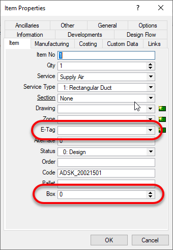
The two ITM properties I found are “BOX” and “E-Tag“.
BOX is only visible from CAMduct. It’s intended purpose appears to be for specifying a “Box” for the ITM in question for shipping purposes but you could use it or anything. Despite it being visible only in CAMduct, using COD Scripts, you can read and write it from ESTmep or CADmep too.
E-TAG is visible from any of the Fabrication products. It’s used for Equipment Tags. You can see both properties from here if in CAMduct or only E-Tag is ESTmep or CADmep.
Scripts Updated
All Debug Scripts – Nothing major, just formatting in the comments section.
WriteAll_Props (Job).cod – Updated to support BOX & E-TAG properties.
WriteAll_Props (Library).cod – Updated to support BOX & E-TAG properties.