I’ve made a couple updates to the Autodesk Fabrication script libraries. If you use them, you can download updated versions from here.
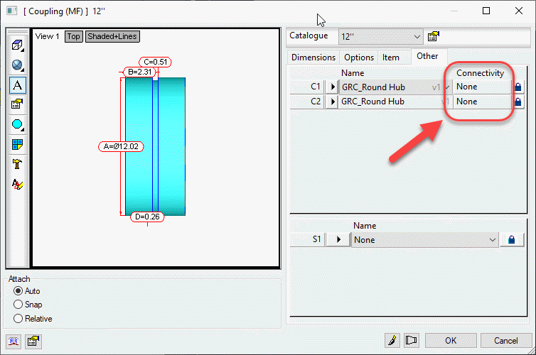
Scripts have been updated to include the Connector Material property found on CID/Patterns 522, 1522 & 2512 as shown below…
This property is intended to be used by a connector to specify a alternate material the connector can connect to. This allows a coupling to connect to alternate materials such as with transition couplings.
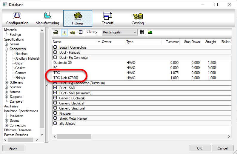
Do you have issues with duplicate entries in your Fabrication Database? These could be proxy entries…those followed by text enclosed within {brackets}. Or they could be identical..if someone made the proxy item permanent,
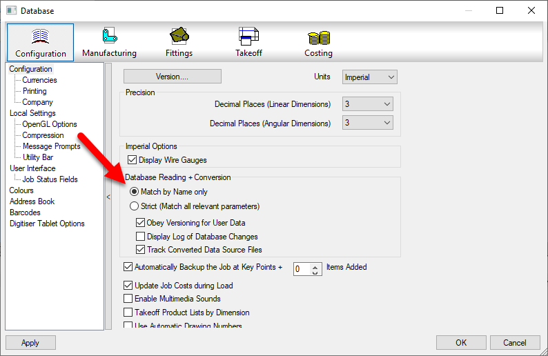
This can be caused by using the Strict matching setting in your database setting. It’s recommended to use Match by Name only.
When you use Strict naming, when you open drawings or MAJ files, the database settings within those files are compared to those in your configuration. If the data is deemed relevant and it varies, even something as small as a number 3 decimals vs. 4 decimals can add another entry into your configuration.
When using Match by Name only, as long as the name (and group) matches, the entry is considered the same and you don’t end up with duplicate entries.
Not sure why Autodesk has this stuffed away under “Civil Engineering” but they’ve released 3 introduction online training sessions for Autodesk Fabrication. If you’re new to Autodesk Fabrication content creation, these will get you up and running with some of the basics.
The only change I’ve found in from 2020 to 2021 versions is the CADmep command DWNLDC Command (DOWNLOADCONTENT Alias) is no longer present. This use to download ITM content from Autodesk’s www.Building3DContent.com site. This site is no longer active and Autodesk has included all the content within the default Imperial and Metric configurations that ship with Autodesk Fabrication Content.
User’s of Trimble’s Managed ITM Content (building-data.net) use to use this command as well. It was just redirected to the Building Data site. It’s unclear how this change will affect them as the core DLL’s used for this process appear to have been removed in 2021 versions of Autodesk Fabrication.
If you’re a user of Trimble’s Building-Data, I’d suggest contacting them for support if you have issues.
Setting up Autodesk Fabrication to communicate with a TigerStop isn’t difficult. But there really isn’t any good resources that explain how to do it. I’ve explained it multiple times to multiple people so I thought it might make sense to document it here.
This following instructions are not needed of you’re using a system like GTP Stratus or MSuite (formerly FabPro1) as they have their own process for interfacing with TigerStops. However, you can easily run a TigerStop from Autodesk Fabrication without buying any additional software. All you need is a TigerStop and Autodesk Fabrication.
Step 1 – Install TigerLink
From Autodesk Fabrication, you’ll be exporting CSV files. TigerLink is a free software from TigerStop that will take those CSV files and break them down and reformat them into files your Tigerstop software can use.
You can get TigerLink software from TigerStop.Com. Go there and search for “TigerLink” and download the latest version (6.x used in this documentation).
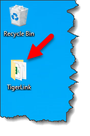
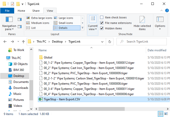
Once installed, you’ll notice a TigerLink folder on your desktop…
And an icon in your system tray…
Right-Click on the TigerLink icon in your system tray and select Open. This will display the following dialog. TigerLink can do several things but we only want it for one purpose. You’ll want to ensure the Auto Connect toggle is Unchecked so that TigerLink does not look for a TigerStop machine.
Be default, TigerLink runs automatically when you start your system and clearing this toggle will prevent it from warning you that there was no machine found. If you don’t want it to run automatically, remove the shortcut it places in the Windows Startup folder.
For now, close the dialog. Then, Right-Click on the system tray icon again and choose Exit. We don’t want the software running when we do our initial configuration a little later.
Step 2 – Creating Your Fabrication Export (Items)
For Tigerstop to work, you need to export data from Autodesk Fabrication. Tigerstops need a minimum of 2 pieces of information. One is a length (decimal format) , the other a quantity. That’s it. However in practice, you’ll want a little more information.
Cutting Pipe is one of the primary uses for TigerStop. So we need to configure a CSV export to do this. But let’s also plan the data we want. We may want to export all types of pipe and sizes in a single export. But you can’t cut mixed materials or sizes from the same stock. So we’ll need material and size in our export so TigerLink can use those fields to break down the data. Let’s breakdown our list of data fields here that we’ll want to send to the TigerStop….
Number
Property
Purpose
0
Item CID
This won’t be output but is used in the Report to filter the Exports to CID 2041 (pipe) only.
1
Item Quantity
Required by TigerStop
2
Item Centerline Lenth
Required by TigerStop. Must be decimal.
3
Job File Name
May be helpful in the TigerTouch display for the operator
4
Item Number
We want to know the piece number for a label
5
Item Description
This typically holds the “Size” of pipe in product listed ITMs. e.g. 1/2″, 3/4″, etc. TigerLink will use this data so files are separated by “Size”. We’ll also use it on the label.
6
Item Centerline Length
We’ll include this again formatted in Ft-Inch for the shop guys who may want that on the labels
7
Item Material Name
Tigerlink will use this data so files are also separated by material name. .e.g. Copper vs PVC vs Cast Iron, etc.
8
Item Spool Name
We’ll want this on the label too.
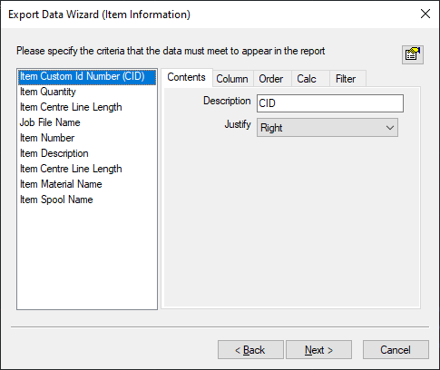
Use the CSVEXPORT command in CADmep to create your export report. When done, your report configuration might look like the following….
When your report is done, the resulting data might look like the following. Notice how all the sizes and materials are mixed together. This is what TigerLink will fix for us.
Qty,Length,Job Name,Item No,Description,Length,Material,Spool
1,39.146,Sample Data Export,12,4'',3'-3 1/8",Pipe Systems: Cast Iron,
1,40.421,Sample Data Export,12,4'',3'-4 3/8",Pipe Systems: Cast Iron,
1,48.250,Sample Data Export,12,4'',4'-0 1/4",Pipe Systems: Cast Iron,
1,11.835,Sample Data Export,12,4'',11 7/8",Pipe Systems: Cast Iron,
1,42.242,Sample Data Export,10,2'',3'-6 1/4",Pipe Systems: Cast Iron,
1,21.542,Sample Data Export,10,2'',1'-9 1/2",Pipe Systems: Cast Iron,
1,18.024,Sample Data Export,8,2'',1'-6",Pipe Systems: Cast Iron,
1,35.939,Sample Data Export,6,3'',3'-0",Pipe Systems: PVC,
1,22.101,Sample Data Export,6,3'',1'-10 1/8",Pipe Systems: PVC,
1,22.101,Sample Data Export,6,3'',1'-10 1/8",Pipe Systems: PVC,
1,54.987,Sample Data Export,6,2'',4'-7",Pipe Systems: PVC,
1,22.101,Sample Data Export,6,2'',1'-10 1/8",Pipe Systems: PVC,
1,22.101,Sample Data Export,6,2'',1'-10 1/8",Pipe Systems: PVC,
1,16.664,Sample Data Export,6,2'',1'-4 5/8",Pipe Systems: PVC,
1,17.845,Sample Data Export,4,2-1/2'',1'-5 7/8",Pipe Systems: Carbon Steel,
1,14.678,Sample Data Export,4,2-1/2'',1'-2 5/8",Pipe Systems: Carbon Steel,
1,33.388,Sample Data Export,4,2-1/2'',2'-9 3/8",Pipe Systems: Carbon Steel,
1,38.282,Sample Data Export,4,2-1/2'',3'-2 1/4",Pipe Systems: Carbon Steel,
1,12.919,Sample Data Export,2,3/4'',1'-0 7/8",Pipe Systems: Copper,
1,13.923,Sample Data Export,2,3/4'',1'-1 7/8",Pipe Systems: Copper,
1,7.293,Sample Data Export,2,3/4'',7 1/4",Pipe Systems: Copper,
1,10.252,Sample Data Export,2,1/2'',10 1/4",Pipe Systems: Copper,
1,10.252,Sample Data Export,2,1/2'',10 1/4",Pipe Systems: Copper,
1,10.252,Sample Data Export,2,1/2'',10 1/4",Pipe Systems: Copper,
1,19.558,Sample Data Export,2,1/2'',1'-7 1/2",Pipe Systems: Copper,
1,19.558,Sample Data Export,2,1/2'',1'-7 1/2",Pipe Systems: Copper,
Step 3 – Configure TigerLink via XML
TigerLink uses the file “C:\Users\<user>\AppData\Roaming\TigerLink6\CutListLinks.xml” to understand how to process exports. We’ll edit this file in Notepad. If you’re familiar with editing XML, it’ll be easy and you may want to use an XML editor however Notepad will be just fine.
I highly recommend making a backup copy of the CutListLinks.xml file in the event you ever need to start over. If you recall the dialog for TigerLink, it listed a number of Export formats in the left column. Each export format are enclosed between a set of XML tags named <LinkType> & </LinkType>.
I’m never going to use any of those formats so I delete all of them from CutlistLink.xml except a single entry which we’ll edit for our purposes. Take some time to study the file before editing. It’s not difficult to see what’s going on with a little close examination.
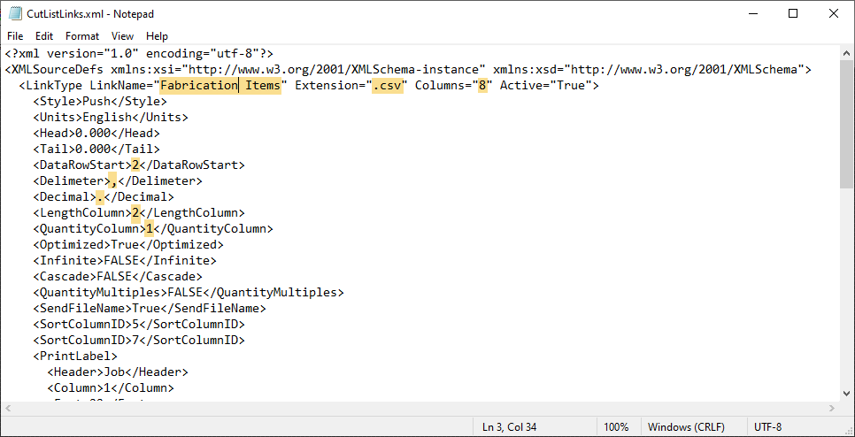
When we have only one set of <LinkType> & </LinkType> tags, we’re ready to start editing. I’ve highlighted the lines that I edited and/or verified in the following image…
Edit the Link Name which is the name of the Export configuration that will display in the left column of TigerLink.
Verify the Extension matches that of the export…CSV in this case.
As you recall, we have 8 columns of data in our export so use the Columns field configures this.
The DataRowStart tells TigerLink that the data starts on row 2 as our export has headers. Adjust as your export report requires.
Delimiter is set to a comma for a CSV but if your data has commas, you may need to use a different character.
Verify Decimal is set as required. Typically only different in some other countries.
LengthColumn tells TigerLink which column is the length TigerStop will use to drive the machine.
QuantityColumn tells TigerLink which column stores the quantity of parts.
At this point, we’ll ignore the other data as it’s easier to set via the TigerLink interface. Save your CutListLinks.xlm file and restart TigerLink.
Step 4 – Configure Tigerlink via User Interface
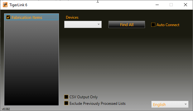
When you restart TigerLink, your version should look similar to the following…
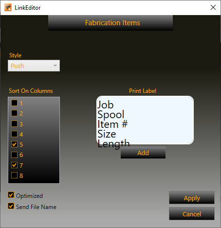
The checkbox next to Fabrication Items tells TigerLink that this Export configuration is active and ready to be used. If you Right-Click on Fabrication Items and select EDIT, you get to the configuration user interface as shown below…
Here, we’ll want to do several things to finalize your configuration.
Put a check-mark next to Column entries 5 & 7. These columns hold the Size (Item description) and Material Name. This tells TigerLink that for this export, anytime there’s a new Size and/or material, it belongs in a separate file.
Unless you’re doing something unique, Style should be set to Push
Optimized tells TigerLink that the material will be optimized for best yield/utilization when nesting.
Send File Name is not required but can be used to display the file name on the TigerStop system.
Use the Add button to add data fields to your label. You can add a lot but TigerStop’s label system only works with up to 5 lines. Drag where you want and Right-Click to edit the header, font size and assign to a data column. Thje preview isn’t the most accurate as you can see. My data is off the display but does print properly. You can later go into the CutListLinks.xml file and get a little more fine control over the font size and placement in the <PrintLabel> & </PrintLabel> XML tags.
You’re now done configuring TigerLink and Fabrication. The only thing left is to process data from an export.
Step 5 – Process Fabrication Exports
To process data from an export, take a file with Fabrication piping in it and run the CSVEXPORT command. Once you;ve run the report you created earlier, look for the the CSV file and copy or move it to the TigerLink folder on the Desktop. Once the file is in that folder, TigerLink will process the file and break it into separate *.tiger files. One for each Material and Size if pipe.
These *.tiger files are what the TigerStop machine will use to cut your pipe.
If your CSV file is not processed into separate files, verify that the TigerLink software is running before you copy your CSV to the Desktop folder. Also make sure that the Fabrication Items entry in the TigerLink interface is selected to make sure it’s active.
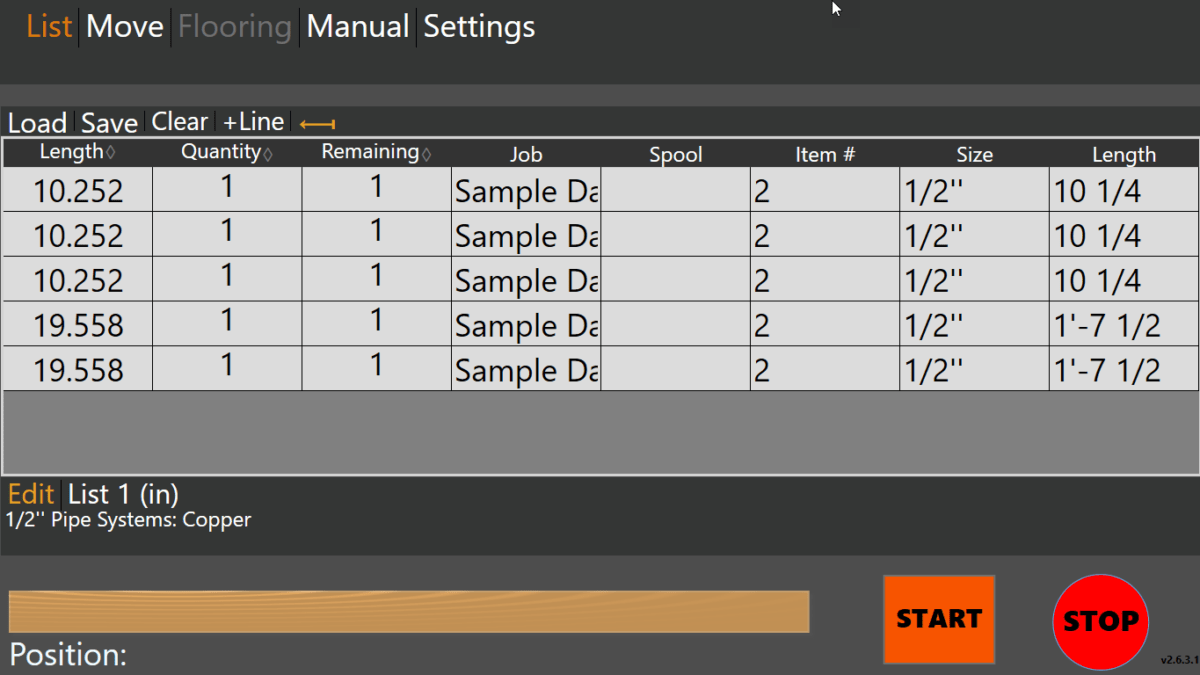
The following image shows how your file should look once opened in the TigerTouch interface…
Summary…
Ancillaries can be cut on a TigerStop in a similar way. Use the ANCILLARYEXPORT command to setup your ancillary exports. Using Ancillary Type and Names, you should be able to generate reports for your TigerStop to cut ancillaries.
Because filtering is limited, it may be a little harder to get a single export for all ancillaries. You may find it’s easier to create a report for each ancillary type. As long as all reports for Ancillaries have the same fields and number of columns, you should be able to just add a single “Fabrication Ancillaries” entry to the TightLink’s CutListLinks.XML file to process any of them.
For a copy of the CutListLinks.xml file and CSV Export report used in this example, you can download them from this file…
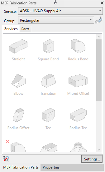
If you’re using Revit 2018 or 2019 with Fabrication Parts, you may notice that upon loading or reloading your configuration some (or many) of your parts become “Invalid”.
I’m not talking about Fabrication Parts whose CID/Pattern isn’t supported in Revit. I’m referring to perfectly valid Fabrication Parts. Parts that once worked. They may even be currently in your model but are no longer active in your Parts Browser. Here’s a couple examples…
You may even notice valid parts become invalid after unloading a service or that invalid parts become valid again after loading a new service.
What’s happening is that your Fabrication Configuration’s Image Cache has become corrupt. The issue is in Revit 2018 and 2019. Revit 2020 does not experience the issue. Whatever changed in Revit 2020 made it more resilient to a corrupt image cache.
The only known fix until recently was editing your service template. You would have to remove and re-add the part. Reloading the Fabrication Configuration in Revit and it would be fixed. Unfortunately, future database changes would often revert back to the invalid state.
Quick and Dirty Work-Around (Revit 2019 Only)
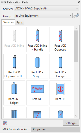
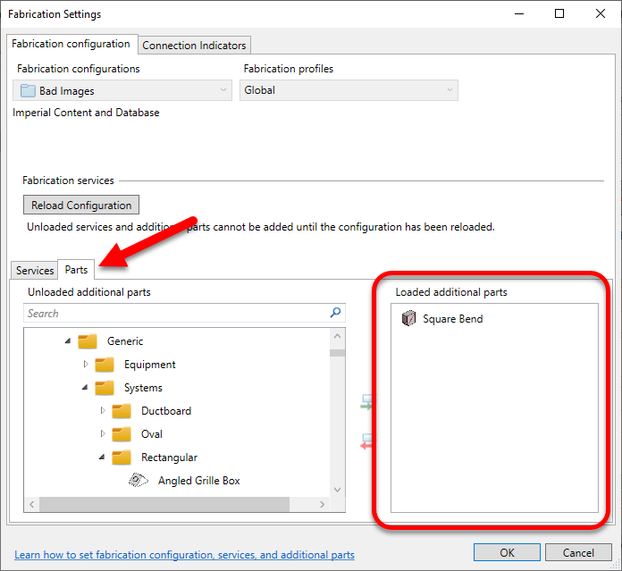
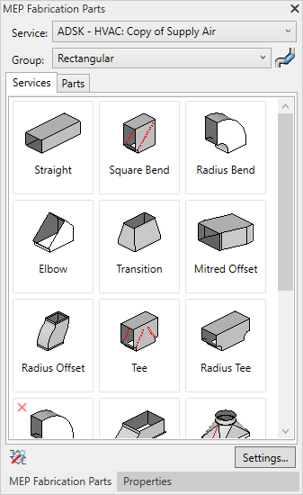
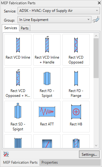
If you’re using Revit 2019, there is a quick and easy work-around. That’s assuming you only have a few parts that are invalid. To work around the issue, reload your Fabrication Configuration and individually load the invalid part in the Parts tab. The following image shows one invalid part added to the Parts tab.
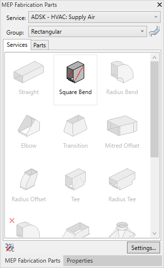
Once added, the Part then becomes valid in the Parts Browser.
A Permanent Fix (For both Revit 2018 & 2019)
The prior work-around was only available in Revit 2019. This didn’t help Revit 2018 projects which do not have the Parts tab in Fabrication Settings.
To properly fix the issue, you need CADmep. Load your Fabrication Configuration in CADmep. Once loaded, find an open area of your service and press CTRL+SHIFT+Right-Click and select Clear Cache.
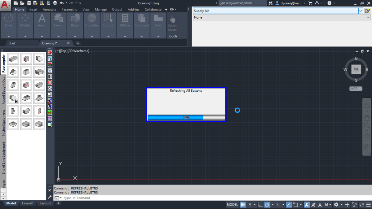
Next type the REFRESHALLBTNS command. You’ll see a progress bar while CADmep refreshes your button image cache.
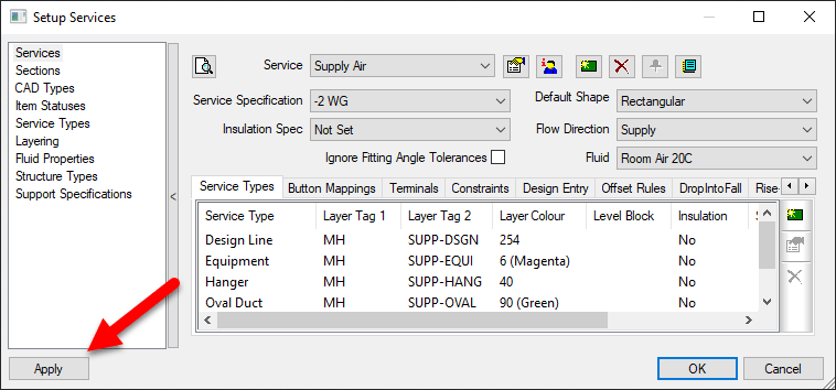
At this point, your button cache should be rebuilt. However I’ve seen instances where you have to “coerce” or otherwise persuade CADmep into saving it back to disk. To verify the changes are saved, go to the Service Editor and click the Apply button then close the dialog.
At this point, you should be all set. If you go back to the problem Revit file and reload your Fabrication Configuration, you should see the Fabrication Part become active again.
Preventing Future Corruption
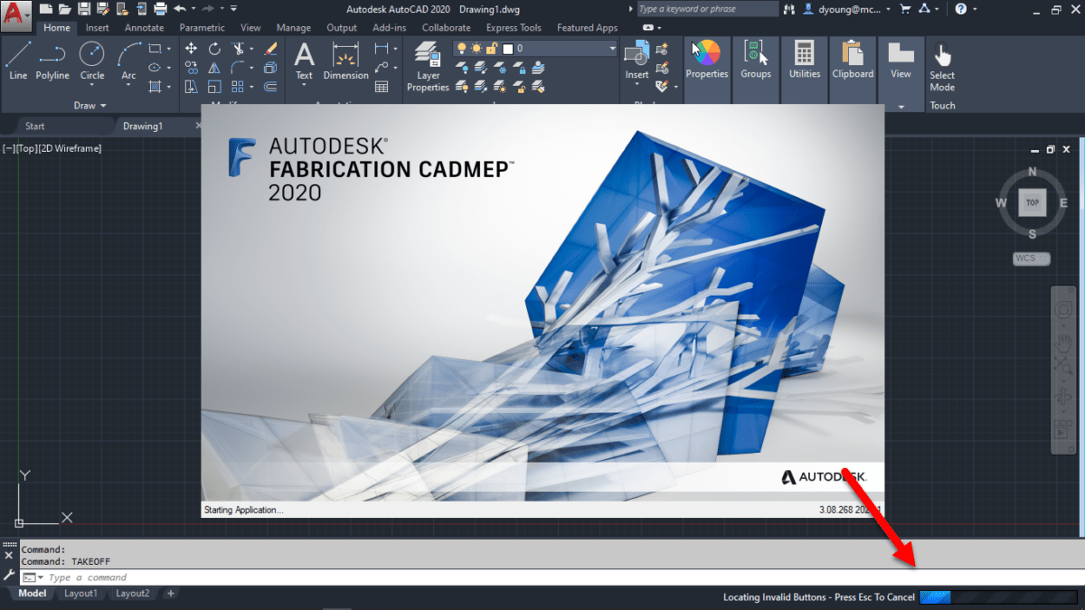
To prevent future corruption, you first need to understand how it happens. When loading CADmep, you may have noticed the “Button Validation” as shown in the following image…
Because this can be a slow process, most users simply hit the Escape key to terminate the validation. This isn’t a big deal for a user. For a database administrator, this can leave your image cache partially built and corrupt it.
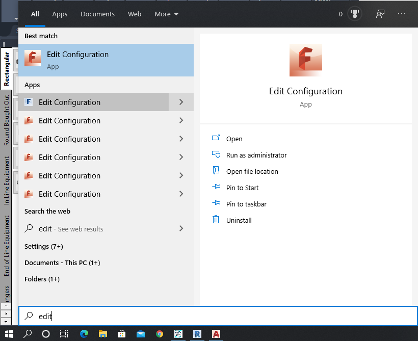
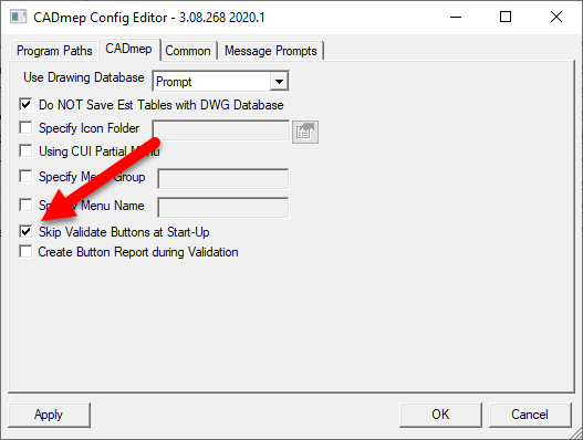
While you can simply stop canceling the process, the better option is to prevent it in the first place. By default, CADmep enables Button Validation. But you can turn it off. To do this, use the Edit Configuration utility that comes with CADmep.
Note that this utility is named the same between versions and between CADmep, ESTmep and CAMduct products. It may be tricky to pick the right one. You need to select the one that comes with CADmep.
You also need to perform this for each CADmep version that’s installed. To help, you may want to choose the Open file location option. This will bring you to the folder with the shortcuts. You can then easily navigate to the proper version of Edit Configuration that you’re looking for.
When you run the utility, it’ll prompt for a configuration. You can pick any, it doesn’t matter. The setting to change is not specific to the configuration, only the product and version for the currently logged in user. The following image shows the Skip Validate Buttons at Start-Up option.
Select this option and the next time you launch CADmep, you’ll no longer see the button validation. This prevents you from canceling out of the validation as well as speeds loading of CADmep.
Credit Goes To…
Special thanks to Martin Schmid and Craig Farish of Autodesk for helping with this issue. We’d been experiencing this issue on and off for over 1/2 a year. Autodesk Support had indicated that nobody else had reported the issue and provided the 2019 work-around. They repeatedly assured me it was fixed in 2020 and not a problem with my data. They had no fix for 2018 which is used by several projects.
After experienced a large volume of invalid buttons, our database administrator spent 6 hours before users arrived rebuilding service templates. The the issue resurfaced within hours of a simple database update. With $5k-10k of lost productivity over 2 weeks with several detailers unable to model certain services, I called in a favor with Martin and Craig. They quickly had their team analyse our data and identify the fix.
I’ve since run into 4 other companies experiencing the same issue and this fix has worked flawlessly for them as well. Hopefully you’ll not need it but if you do, it’ll save you load of time, frustration and money.
Autodesk Fabrication configurations can Compress their data files. It’s a good idea to have this enabled. Not only does this make the files smaller and take up less space, it makes them faster to load. This increases your performance as the data is expanded in memory as opposed to read more data from disk.
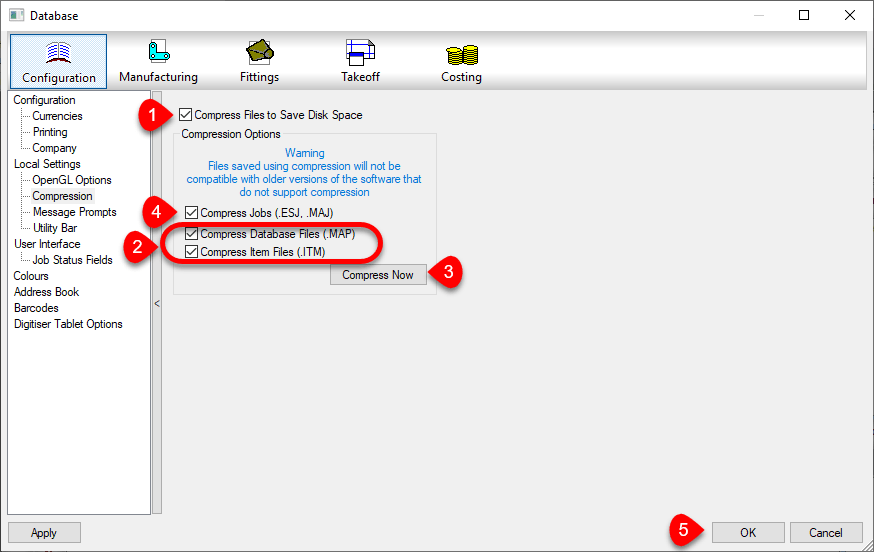
You can enable this option in your database settings. Doing this does not automatically compress existing data that’s not already compressed. The following image shows a suggested sequence of operations. This would both enable compression and compress the existing data.
First Enable Compression by selecting the Compress File to Save Disk Space toggle. Future writes to data tables will be compressed when if they are configured to.
Next, enable the toggles for Compress Database Files (.MAP) and Compress Item Files (.ITM) options. This will tell Fabrication to Compress the existing Database and Item files. Also, “unselect” the Compress Jobs (.ESJ .MAJ) option.
Click the Compress Now button. This compresses the Database and ITM files but will not scan your ESTmep and CAMduct job files.
Once compressed, select the Compress Jobs (.ESJ .MAJ) option. This will compress all Future ESJ and MAJ files but not existing ones. If you wanted, you could have left that option selected in Step 2. However it would significantly increase the time it takes to perform the compression process. Because most of your ESJ and MAJ files are likely past jobs, there’s really no value in processing them now….but you could.
Press the OK Button to save these settings.
Check Settings for Each Product, Version and User of Each Computer
You should also know that these settings are NOT saved in your configuration. The file that stores these settings is located here…
You can tell by the folders, that this setting is stored separately for each user on a computer. Because each product and each version is part of the path, those variations need to be set too.
Because Best Practice #9 tells you to use only one version for database administration, version may seem unimportant. But it IS important to know when you upgrade to a newer version for administration. Those versions should also have these settings reviewed.
Every user who does work in your database, should check each product and version for those settings. If they don’t, your work may compress files while their work may decompressed them.
Because clicking this just once makes it do it’s magic in your database, you don’t need to click the Compress Now button for each version, user, product or computer. The options merely need to be Set., telling those products what they should/should compressed or decompressed.
Every once and a while, a Fabrication Configuration can lose data or become corrupt which leaves Revit unable to access it. This after you’ve already been working in a model and using the configuration without issue.
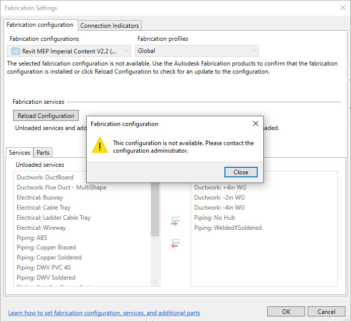
When this happens, it’s likely a result of the Fabrication Configuration loosing it’s GUID or “Global Unique Identifier”. You really only notice when attempting to reload the configuration in one of your existing models. The error will look like the following image…
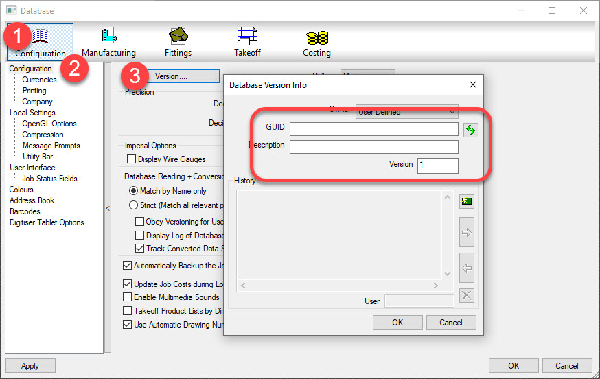
When you launch of the other Fabrication products (CADmep, ESTmep or CAMduct) you can view the data from the database editor. In the image below, you can see the data is missing.
Retrieving Lost Data
The good news is that you can the data back. For this, we’ll use Revit and Dynamo, Revit’s visual programming environment.
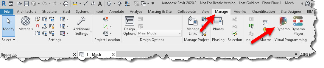
Start Revit and open up one of your existing project that already had a Fabrication Configuration loaded. From the Manage ribbon, click the Dynamo button.
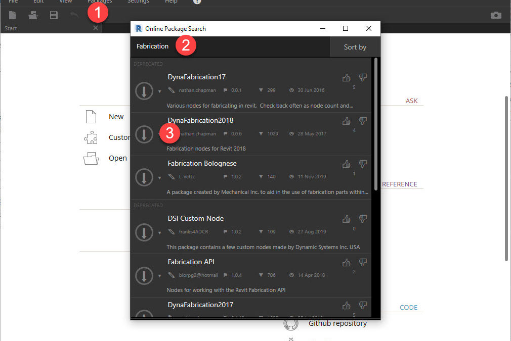
Once in Dynamo, you’ll need to load a Fabrication Dynamo package. Click the Package menu to display the Online Package Search dialog. You’ll need to wait a little while for the dialog to populate. Once populated, you can type Fabrication in the search box. In the results, select the DynaFabrication2018 package. Next, click the down arrow button on the left to install it as shown in the following image…
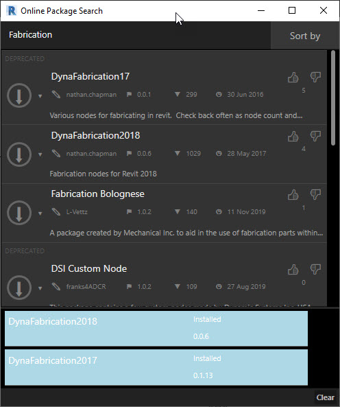
Once installed, the dialog will show the loaded modules at the bottom. It should look like the following image…
After the Dynamo packages are installed, you can build a Dynamo program that will extract the needed data. But instead of walking you through that, simply download, unzip and open the Dynamo program I’ve already created.
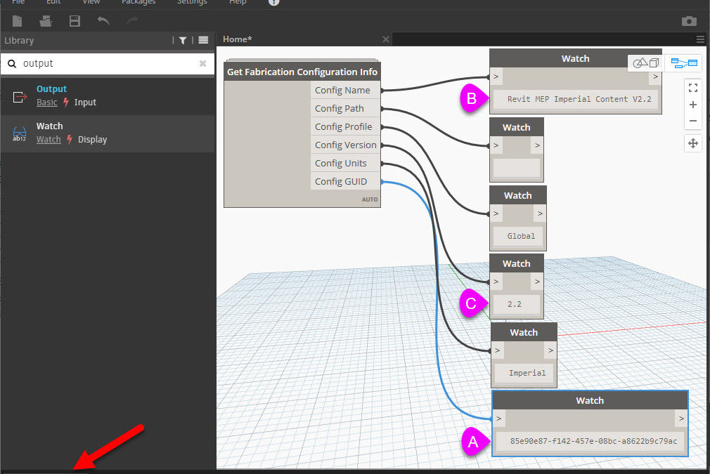
One Dynamo program Get Missing Fabrication GUID.dyn is loaded, your Dynamo screen should look like the following image…
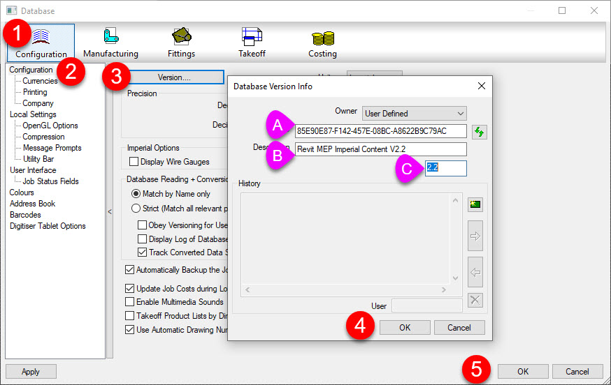
In the lower right corner, if the button says Manual click the Run button otherwise if it’s set to Automatic, the information you need is already populated. Record the data in the fields marked A, B & C. This is what you’ll enter back in the database.
Add Data Back to the Fabrication Configuration
Launch of one the Fabrication products (CADmep, ESTmep or CAMduct). In the database editor, enter the information from Dynamo into the fields marked A, B & C as shown below…
Exit the database editor and exit from the Fabrication product you launched. If you still have Revit/Dynamo loaded, close both. Now, relaunch Revit again and open the model you opened before.
When you go to reload the configuration again, Revit should successfully find and reload your configuration.
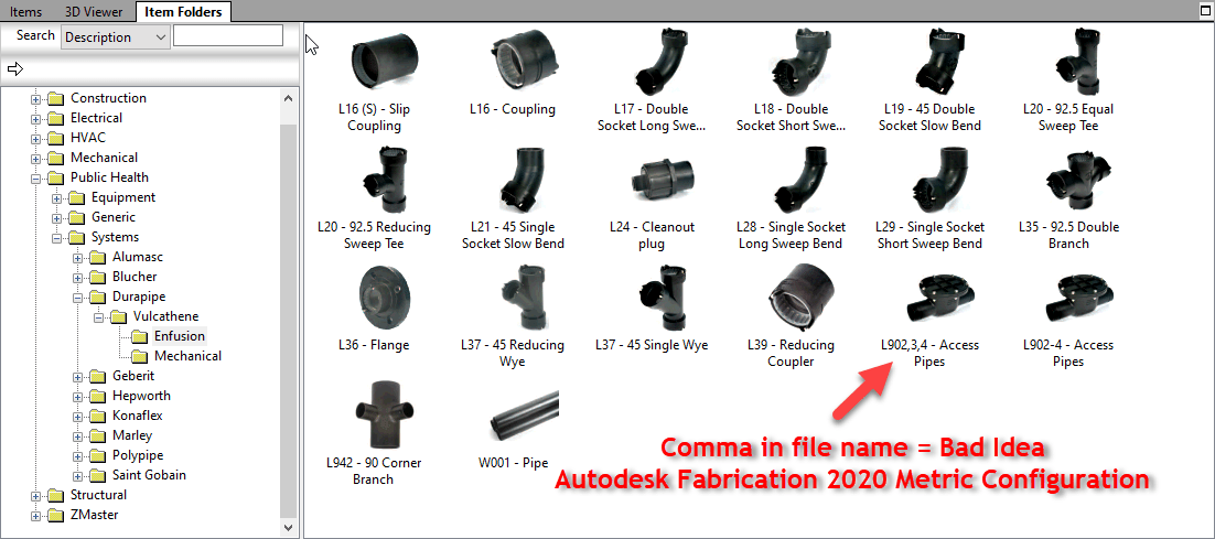
Don’t use Commas (,) in Database Entry Names, ITM File Names, Don’t Use Them Anywhere.
Similar to Best Practice #1 (Don’t use Double Quotes), you should avoid using commas. Commas are the delimiting character in a CSV file. Using a comma can throw off the data columns in data exports that use the CSV file format.
Below, you can see Autodesk let a comma slip into a file name in their Metric Configuration.Yes – Ancillary in Ancillary Kit
CADmep, ESTmep and CAMduct all use the concept of an Attacher. This is what tells Fabrication which way to route elbows and branches.
Most people know how to place and rotate the Attacher. There are a few other tricks to working with the Attacher that you may not know about.
Up or Down, How to Get Around
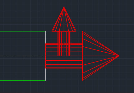
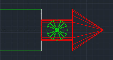
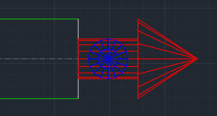
Depending on your view orientation, you may notice part of the Attacher turns from Red to Blue or Green. As you rotate the Attacher it’s color will change to indicate the direction the arrow is pointing.
Green = Grass (Attacher is pointing away from you)
Blue = Sky (Attacher is pointing toward you)
Rotation Tricks
Depending oh which program you’re in (CADmep, ESTmep or CAMduct) and the keys you press, the Attacher rotates differently. Here’s a chart explaining those nuances.
Rotation
Method
CADmep
ESTmep
CAMduct
90 Degrees CCW
Click
Yes
Yes
Yes
90 Degrees CW
Shift+Click
No
Yes
Yes
180 Degrees (Flip)
Ctrl+Click
Yes
Yes
Yes
15 Degrees CCW
Alt+Click
Yes
No
No
CADmep – Click Attacher to Rotate Counter Clockwise 90 DegreesCADmep – Ctrl+Click Attacher to Rotate 180 Degrees (Flip)CADmep – Alt+Click Attacher yo Rotate Counter Clockwise 15 DegreesESTmep / CAMduct – Click Attacher to Rotate Counter Clockwise 90 DegreesESTmep / CAMduct – Shift+Click Attacher to Rotate Clockwise 90 DegreesESTmep / CAMduct – Ctrl+Click to Rotate Attacher 180 Degrees (Flip)