Autodesk Fabrication: Best Practice #14

Eliminate All Broken Service ITM’s

Your services should not have broken links to ITM’s. Not only is it sloppy database management, it can slow performance of your database.

Use the Path Repair Tool to find (and fix) broken links in your services.

Right-Click and empty area of your Service Palette and select Path Repair Tool.

When you run the Path Repair Tool you’ll be asked to select a mapping file. You can click cancel and the tool will continue on. When it’s done, you’ll have a list of broken paths copied to the Windows Clipboard that you can paste into a file.

From this file, you can then create a mapping file. The mapping file is merely a text file in the format….

OLD PATH/NAME,NEW PATH/NAME

So the data you paste from the clipboard is good starting point, it lists all the broken paths. There may be duplicate paths listed if the path is used in multiple service templates. It’s ok to remove the duplicates.

Simply ass a comma after the broken path name and enter the new, corrected path. Once done, you can save the file and use it when you run Path Repair Tool again. It’ll then go and fix all those broken paths.

NOTE: This repair technique does NOT work if you have commas in your folder or file names. (See Best Practice #11)

Autodesk Fabrication: Best Practice #13

Use “Match by Name only” in Database Settings

Do you have issues with duplicate entries in your Fabrication Database? These could be proxy entries…those followed by text enclosed within {brackets}. Or they could be identical..if someone made the proxy item permanent,

This can be caused by using the Strict matching setting in your database setting. It’s recommended to use Match by Name only.

When you use Strict naming, when you open drawings or MAJ files, the database settings within those files are compared to those in your configuration. If the data is deemed relevant and it varies, even something as small as a number 3 decimals vs. 4 decimals can add another entry into your configuration.

When using Match by Name only, as long as the name (and group) matches, the entry is considered the same and you don’t end up with duplicate entries.

Autodesk Fabrication: Best Practice #12

Compress Fabrication Data Files.

Autodesk Fabrication configurations can Compress their data files. It’s a good idea to have this enabled. Not only does this make the files smaller and take up less space, it makes them faster to load. This increases your performance as the data is expanded in memory as opposed to read more data from disk.

You can enable this option in your database settings. Doing this does not automatically compress existing data that’s not already compressed. The following image shows a suggested sequence of operations. This would both enable compression and compress the existing data.

  1. First Enable Compression by selecting the Compress File to Save Disk Space toggle. Future writes to data tables will be compressed when if they are configured to.
  2. Next, enable the toggles for Compress Database Files (.MAP) and Compress Item Files (.ITM) options. This will tell Fabrication to Compress the existing Database and Item files. Also, “unselect” the Compress Jobs (.ESJ .MAJ) option.
  3. Click the Compress Now button. This compresses the Database and ITM files but will not scan your ESTmep and CAMduct job files.
  4. Once compressed, select the Compress Jobs (.ESJ .MAJ) option. This will compress all Future ESJ and MAJ files but not existing ones. If you wanted, you could have left that option selected in Step 2. However it would significantly increase the time it takes to perform the compression process. Because most of your ESJ and MAJ files are likely past jobs, there’s really no value in processing them now….but you could.
  5. Press the OK Button to save these settings.

Check Settings for Each Product, Version and User of Each Computer

You should also know that these settings are NOT saved in your configuration. The file that stores these settings is located here…

C:\Users\<user>\AppData\Local\Autodesk\Fabrication <version>\<product>\UserOpt.MAP

<user> = User's Windows Login Name
<version> = Autodesk product version. (e.g. 2018, 2019, 2020, etc.)
<product> = Autodesk Fabrication product (e.g. CADmep, ESTmep, CAMduct)

You can tell by the folders, that this setting is stored separately for each user on a computer. Because each product and each version is part of the path, those variations need to be set too.

Because Best Practice #9 tells you to use only one version for database administration, version may seem unimportant. But it IS important to know when you upgrade to a newer version for administration. Those versions should also have these settings reviewed.

Every user who does work in your database, should check each product and version for those settings. If they don’t, your work may compress files while their work may decompressed them.

Because clicking this just once makes it do it’s magic in your database, you don’t need to click the Compress Now button for each version, user, product or computer. The options merely need to be Set., telling those products what they should/should compressed or decompressed.

Autodesk Fabrication: Best Practice #11

Don’t use Commas (,) in Database Entry Names, ITM File Names, Don’t Use Them Anywhere.

Similar to Best Practice #1 (Don’t use Double Quotes), you should avoid using commas. Commas are the delimiting character in a CSV file. Using a comma can throw off the data columns in data exports that use the CSV file format.

Below, you can see Autodesk let a comma slip into a file name in their Metric Configuration.Yes – Ancillary in Ancillary Kit

Autodesk Fabrication: Best Practice #10

Don’t use Ancillaries with Breakpoints inside an Ancillary Kit.

Ancillaries are virtual items you can add to your Fabrication configuration. ESTmep users use Ancillaries to help quantify cost and labor. Material quantification for purchasing and/or fabrication is another use for Ancillaries. These are virtual items because they typically don’t affect modeling or coordination. They aren’t even typically drawn yet they are critical to your fabrication as a purchased, fabricated or installed item.

Database view of an Ancillary entry

At times, you many need multiple Ancillaries associated with an item. However the fabrication software typically only allows you to assign a single ancillary to an item or database entry like a connector. For this reason, Autodesk Fabrication includes a type of entry called an “Ancillary Kit” in which you place multiple Ancillaries.

These Ancillary Kits are where you can group multiple Ancillaries that are often used together. A Bolt, Nut and Washers are a good example of an Ancillary Kit.

Database view of an Ancillary Kit entry

Ancillary / Kit Breakpoints

Often, Ancillary items are defined by the size of the item they are associated with. As an example, a flange gasket would be different depending on the type and size of flange it’s used with. You can configure an Ancillary to have Breakpoints to reference a different parts depending on the size of the item the Ancillary is associated with.

Database view of an Ancillary with Breakpoints

Just like Ancillariess, an Ancillary Kit can also have Breakpoints. Using a flange as our example again, depending on the type and size of a flange, or what it’s connecting to (another flange, valve, pump) it can have different bolt/nut sizes and quantities. You would manage this using an Ancillary Kit with Breakpoints.

Database view of an Ancillary Kit with Breakpoints

Nested Breakpoints

If you watched the example images closely, you can see Autodesk’s own database breaks this Best Practice rule. The rule is to never add Ancillaries that use Breakpoints to an Ancillary Kit. Here’s how to keep that straight…

  • Yes – Ancillary in Ancillary Kit
  • No – Ancillary w/Breakpoints in Ancillary Kit
  • Yes – Ancillary in Ancillary Kit with breakpoints
  • No – Ancillary w/Breakpoints in Ancillary Kit w/Breakpoints

I’ve not tested Autodesk’s configuration for reporting accuracy. I have enough work managing my own fabrication configuration. However I did create a sample of my own and submitted to Autodesk support. After demonstrating inconsistent results with my sample, their recommended guidance was not to use Ancillaries with Breakpoints in an Ancillary Kit.

Based on testing in other data sets, I would say this is sound advice. Even if you can get it to work, the setup and configuration is less intuitive and confusing. Your Ancillary Kit can reference different Ancillary types using different Breakpoint criteria. The Ancillary Kit could also have conflicting Breakpoint criteria (e.g. Length x Width vs Diameter) compared to the Ancillary.

Keeping this Best Practice can create more Ancillary entries as well as make building Ancillary Kits a little more time consuming. But the results will be more predictable and what’s really happening in your configuration will be more obvious and less obscure. Even where Breakpointed Ancillaries do function within an Ancillary Kit, it’s advised to avoid this where possible.

Autodesk Fabrication: Best Practice #7

Don’t work in a Live Sync’d Database

This warrants a little explanation.  Many companies have multiple locations and need to sync Fabrication configurations between those sites. Other companies have their Fabrication configuration copied locally to the users system from a central network location.

To keep from having to manually keep different sites or local computers up to date, it’s natural to look so some of the many technology solutions like Microsoft’s One Drive, Box.net, Dropbox, Google Drive, DFS Replication etc. 

Here’s the problem….most of these solutions sync files in their own order and time frame. You often can’t control when they sync. When using CADmep, ESTmep or CAMduct, just using the software can cause the program to read back from the database files. Many of the database files reference each other using indexes. Take for example, the Specifications and Materials….both of those database areas refer to each other.

When changes are made, what happens is the files get updated where you make the changes, but the two files that get changed, may sync somewhere else at different times. As you’re using the software, if it happens to reread some of the database files when some are sync’d and others aren’t, this can cause unspecified problems.

One of the more common issues is when a system you’ve drawn changes to a completely different system. Have you ever had a Cast Iron No-Hub waste line all of the sudden day it’s Supply Air 2″ Positing Water Gauge?  This is our of sync syncing issues is often the result.

How do you work around this? Try to find sync solutions that allow more control, like after hours sync. I personally like an old batch file running RoboCopy as it allows a lot of control and I can have it fire up when the user logs on. They can also manually run it during the day if I push our a critical update otherwise the get the update tomorrow when they log in. When syncing servers from different sites, I schedule it to run after hours. 

This issue is most common w/CADmep, ESTmep and CAMduct. Because Revit loads and stores your services, it doesn’t read back to the database unless you explicitly tell it to reload the services so it’s risk is greatly reduced to the point where I wouldn’t worry about it.

Now, there are people that are doing local Sync’s in real time. My prior firm, we had some…let say…”creative folks” who would take liberties with the database if they knew it was local. As such, I used Windows OffLine Files to sync a local copy but make it look like it’s still on line. This is a Sync’d local copy and goes against what I recommend above. However, we forced it to rescan frequently so when there were changes, they were small, just a few files and they’d sync quickly about the same time. Larger changes involving a lot of files can open up your risk window to having issues.

If you’re going to use life syncing utilities, proceed carefully and watch for unexplained issues. Making large changes after hours and smaller changing during working hours can help.

And if you’re considering using Window’s Offline Files, prepare for a long learning curve and experiment with yourself first. Offline Files have little control from the User Interface and is best managed with Group Policy.

Autodesk Fabrication: Best Practice #6

Don’t PURGE or COMPACT Your Database When In Use

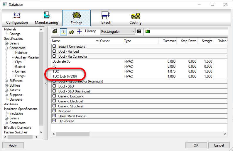
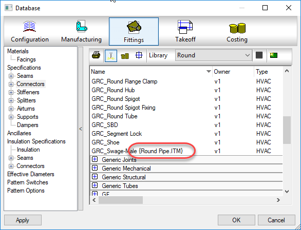
A Fabrication Database that’s well managed should have changes being made. This can mean things like materials, specifications, services, connectors and such may be occasionally deleted and removed. If there are proxy items in your database that have {brackets} around them, they should be made permanent or removed as well.

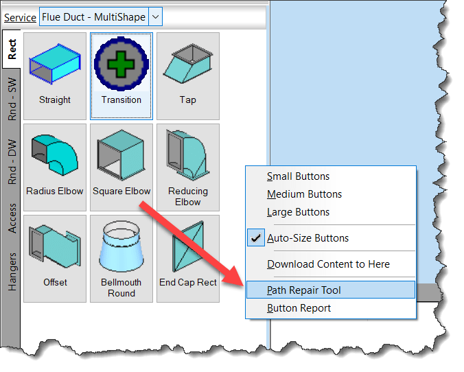
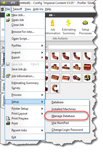
The way to do this is to PURGE and/or COMPACT your database, You can do this by typing PURGEDB on AutoCAD’s command line or by selecting File -> Setup -> Manage Database from ESTmep or CAMduct as sown in the following image.

When you initiate this process, you’ll be presented with a standard “Backup Your Database…” warning which you can click OK to.

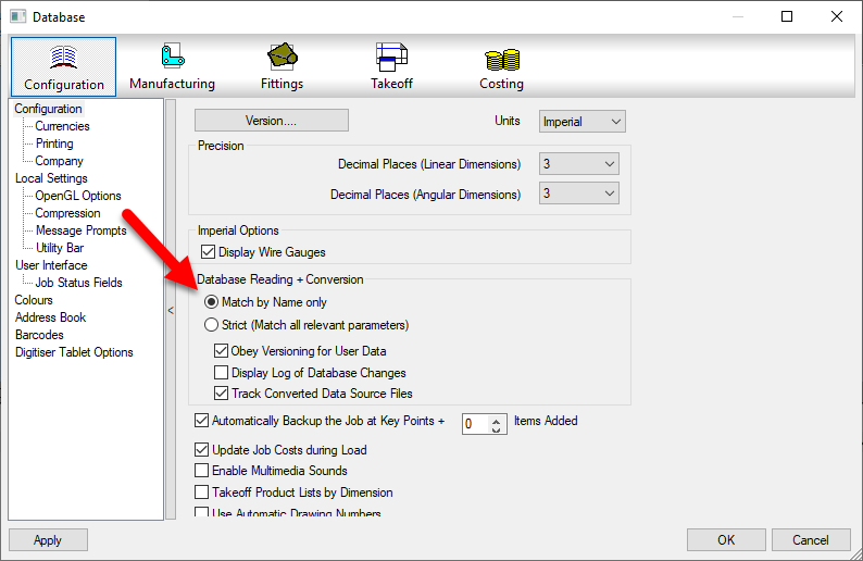
From there, you are then presented with the following dialog.

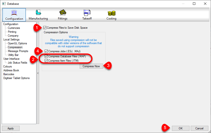
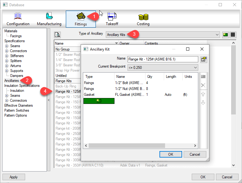
Items that show up here are the ones that show up with {Brackets} in your database, They should either be made permanent or removed in a well managed system.

The Make Permanent option is fairly safe. The items are in your database already there and already have indexes assigned.

On the other hand, the Purge Database option will remove them from your database. When you do this, the’s a chance that some of the database indexes will change as those indexes are how the various database tables relate to each other.

If you do this while others are using the database in CADmep, ESTmep or CAMduct, they already have the database tables loaded into memory. Depending what they are doing, some activities may cause parts of the database to be reloaded while others are not. When this happens, strange things can happen to your drawing…your systems might loose their service or change services or connectors change without notice. More times than not, unless you catch it right away,by the time you find the issue you’ll need to remodel your data or retrieve it from a backup.

In a Database, records are not actually deleted so while the Purge command appears to remove items from the database, it  actually just flags them as being unused so those areas in the database can be overwritten with new data later. This is where Compacting the database comes into play. The Compact the Database Now option will rewrite and re-sequence all the database files and their indexes to recapture that unused space. Again, this causes issues for others who are currently referencing the database and doing work.

While there is danger in using these commands, they should be used to properly manage your database. The key here is to use them after hours when other users are not using the database. Another option would be to do your development work in a copy of the database so nobody is ever “using” the database you’re performing administration work in. When you’re done, you can “copy” this database to the production database but again, after hours when nobody is doing work or you could have all users log out temporarily (perhaps at lunch) and copy the database then.

To the best of my knowledge, this issue is NOT present for those of you using Revit with Fabrication parts. Revit loads in your services and content and caches it in the Revit model. It doesn’t reference the database configuration again while you work unless you manually “reload” the configuration, So unlike CADmep, ESTmep or CAMduct which may reload parts of your database just by using the software, Revit won’t do this unless you manually reload in which care it will reload everything and keep all those database sequences sin check.

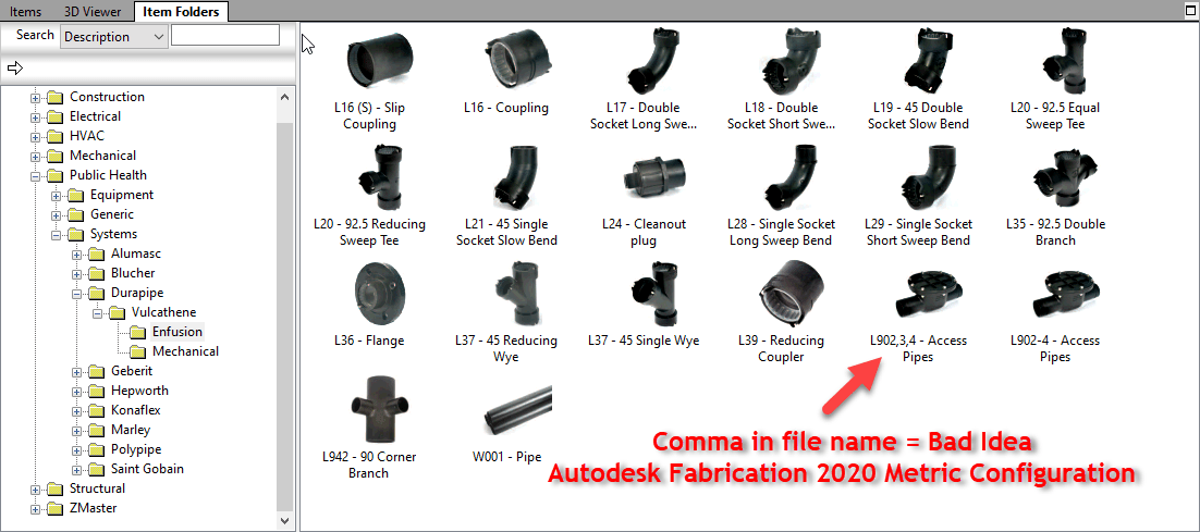
If you’ve ever opened an AutoCAD drawing and your parts appeared orphaned from their services, connectors changed to things that don’t make sense or your Cast Iron NoHub Waste system suddenly reports as Rectangular Supply Air, this likely was the cause and this Best Practice is for you.

Autodesk Fabrication: Best Practice #4

Make sure ALL of your ITM content has a Database ID assigned to it.

A database ID is a unique identifier for content. There should be a single Database ID for any ITM that is NOT Product Listed. For Product Listed ITM’s, there should be Database ID for each entry in the product list.

For ITM’s that are not product listed (typically fabricated sheet metal fittings or other content where the ITM only represents one size, you can put the Database ID in the “Code” field of the ITM Properties as shown in the following image…

For ITM’s that are Product Listed, the Database ID should be in the ID column of the Product List. When you place an instance of a product listed ITM in your model, you select a size from the product list, When you select that size, the Database ID associated with that size it automatically entered into the Code field of the ITM Properties like shown earlier, The following image shows the Database ID column in a Product List…


Why Use A Database ID?

The Database ID is a useful component to managing an Autodesk Fabrication configuration. This Database ID can be referenced by other aspects of Autodesk Fabrication should you choose to use them. The Database ID is what can link your content to….

  • Price lists
  • Fabrication Labor
  • Installation Labor
  • Product Information (ProdInfo)

Even if you don’t use ESTmep for estimating  and don’t want to use the Price and/or Labor features of the database, Product Information is tied to the Database ID and is used to store additional meta data about your content like Manufacturer, Size, Description, etc. Even if you’re not using ProdInfo now, it’s still a good idea to use Database ID’s because adding them to the content is the most time consuming part. It’s easy to add them when building content, more cumbersome later after the fact. If all your content had Database ID’s assigned, it’s much easier to implement ProdInfo, Price and/or Labor later down the road.

The following Video shows how to access the Database ID of Product Listed and Non-Product Listed ITM’s. It also shows you 2 different sizes of a product listed ITM in a drawing and how Autodesk Fabrication automatically assigned the Database ID from the Product List for the corresponding size into the Code field of the ITM Properties.


Key Database ID Takeaways

Here’s a few pointers when working with Database ID’s:

  • Each Database ID should be unique and not assigned to other content or sizes.
  • Managing Database ID’s using a spreadsheet or other database makes managing them much easier.
  • Your database ID can be anything you want but should have some sort of naming standard associated with it.
  • Your Database ID Naming standard can be as simple as a prefix followed by incremental numbers to something complex with special codes and formatting to indicate other aspects of your content. (e.g. Valves, Pipe, Sheetmetal, etc)
  • You can use Autodesk or other Vendors ID’s if they already have them assigned and use your for anything you create or replace them all with your own company Database ID’s if you are particular about naming standards,
  • Don’t reuse ID’s if the content that once used them is now obsolete. Legacy/Archive drawings still reference these numbers. Simply flag them as being obsolete in the Spreadsheet you are managing them with.

Autodesk Fabrication: Best Practice #3

Don’t leave proxy items in your fabrication database.

You’ll notice these as they appear with curly brackets { } around a piece of text like an ITM name or DWG name.

These proxy objects can show up many places. Services, Service Templates, Materials, Connectors, Seams, etc. They occur when an ITM or drawing containing ITM’s references a database entry that no longer exists in your Fabrication configuration. As an example, if you delete a connector from your database, let’s say “Copper Cup” then later add an ITM to your drawing that contains a reference to that connector, it gets added back to your configuration and displays the ITM name in the curly brackets.

If there’s bracketed items in your database they should either be made permanent or deleted. If deleted, they may keep coming back.  If you truly want them gone, you need to find the objects bringing them back and update them to the new item in your database configuration that they should point to.

A properly managed Fabrication database configuration should have everything configured properly. Items with curly brackets are an indication that things are not configured properly.

Future posts will explain various techniques to help identify where these bracketed items come from as well as how to correct them efficiently.


Autodesk Fabrication: Best Practice #2

Don’t use BMP files for ITM Images

If you’ve been using an Autodesk Fabrication configuration for a long time, like back before Autodesk acquired MAP Software Ltd, you may have a lot of content that’s using Bitmap (*.BMP) files. These image files are used on a couple key locations….

1: Service Palettes….

2: Folders Dialog….

If you’re Fabrication configuration uses BMP files for images, you should consider converting them to PNG files. There’s a number of utilities that will do this in bulk for you if you have a lot. My favorite is using TechSmith’s SnagIt Editor but there are others.

Use Windows Explorer and browse to your content. You can use the search functionality in the upper right corner and search on *.BMP to see how many Bitmap images there are. Or you can browse folder by folder looking for them. Hint: Sorting by type can speed with this too.

Once you convert the BMP’s place the PNG files in the same folder using the same name as the BMP and then delete the BMP files. Doing this will reduce the size of the files which in turn speeds the display of your service palettes and folder’s list.