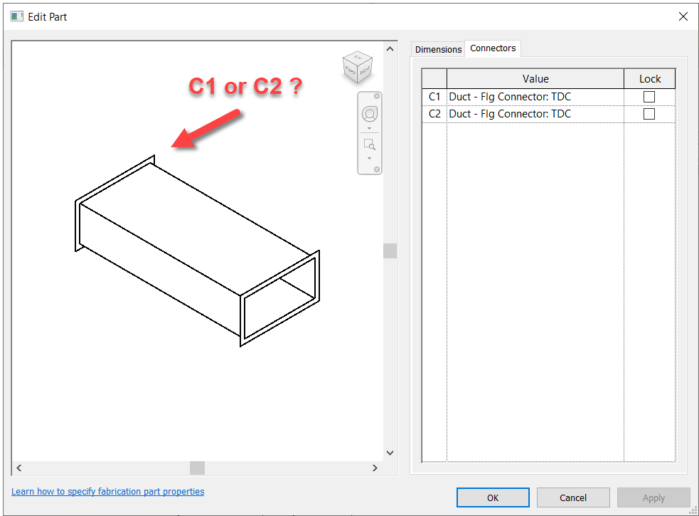
Fabrication Parts in Revit allow you to edit their connectors just like in CADmep. However, unlike CADmep, you can’t simply hover over a connector to determine if it’s C1 or C2.
So if you need to change a connector, you’re essentially guessing which one to change. Trial and error is at best 50% unless you’re lucky.
So how can you improve this “guessing” based workflow?
Thankfully I have a great network of people smarter than myself. I often get the credit for sharing the information but really, the credit belongs to those who show me. In this case, two of my industry friends showed me ways to improve the odds.
Method 1 – Slope
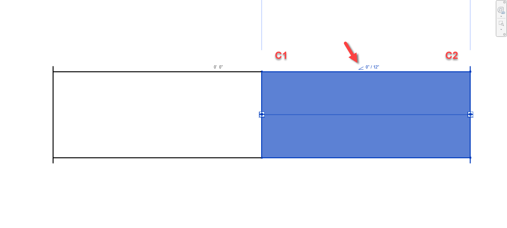
For this first method, credit goes to Liz Fong from MacDonald Miller. When you place a piece of straight pipe or duct, when you select it you’ll see a Slope indicator (< or >). This by default points to the C1 connector.
Duct/Pipe placed defaults the Slope symbol pointing to C1
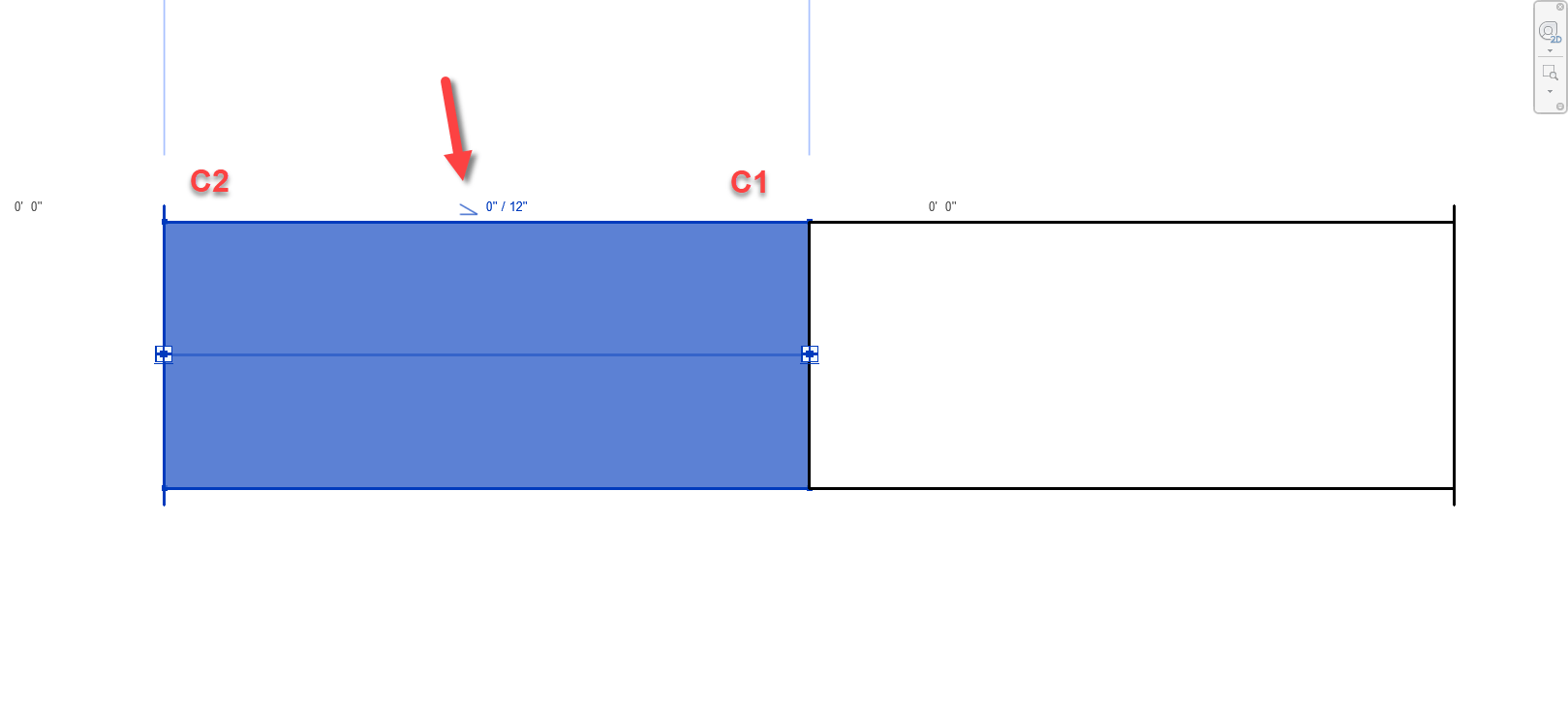
Duct/Pipe mirrored also defaults the Slope symbol pointing to C1
There’s a couple downsides to this approach that may apply in some scenarios….
This doesn’t work for fittings. Only Straight Pipe/Duct.
If you click the Slope Symbol, it changes direction and is no longer accurate.
This should really only affect Plumbing or sloped Grease Duct systems. Otherwise there’s not a lot of reason to change direction on a non-sloped system.
Symbol could still be accidentally clicked and reversed anyway and then be wrong.
Once changed, Slope symbol direction is remembered and there’s no good way to “reset” it.
Still, despite the downsides of this approach, I’m going to go out on a limb and suggest that even on a plumbing system, less that 50% of the slope symbols will be changed from their default. This alone makes this method better than a 50/50 guess like before.
Method 2 – View Cube/Viewing Direction
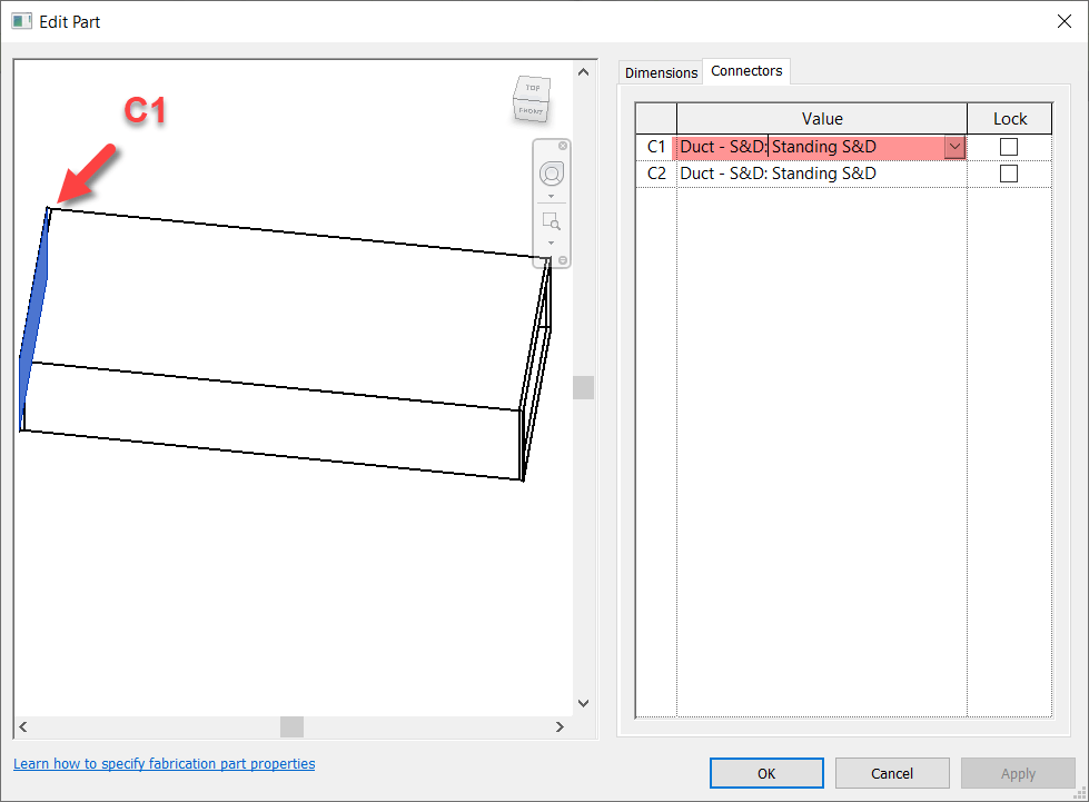
This next method takes slightly more work, but is almost 100% accurate. Credit for this method goes to Alina Y. from JH Kelly.
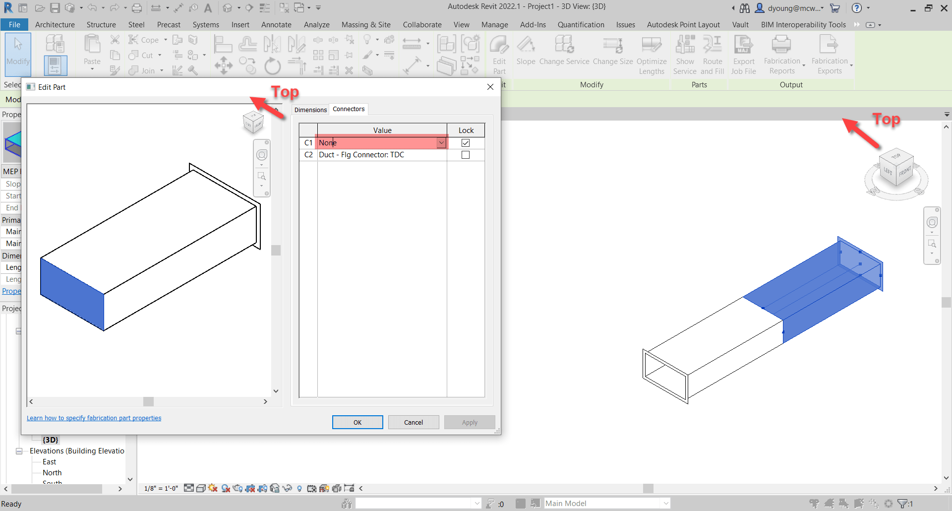
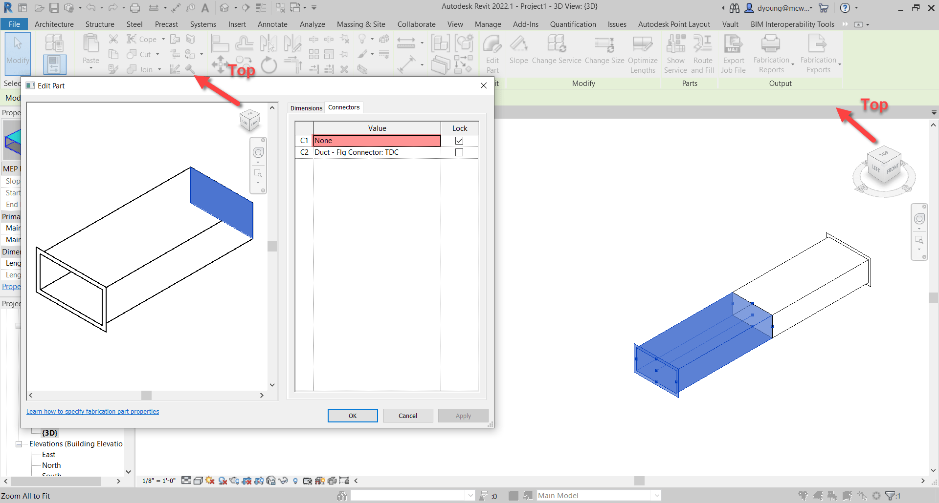
In short, from a 3d view, if you make sure the View Cube in the Part Editor window is aligned to the Revit View you’re in, the fittings is oriented in the same direction in the editor as in Revit. You can then select the connector in the Part Editor window and it highlights the connector end associated with it.
Duct/Pipe placed in Revit matches the editor when View Cubes are aligned. Selected Connector highlights.
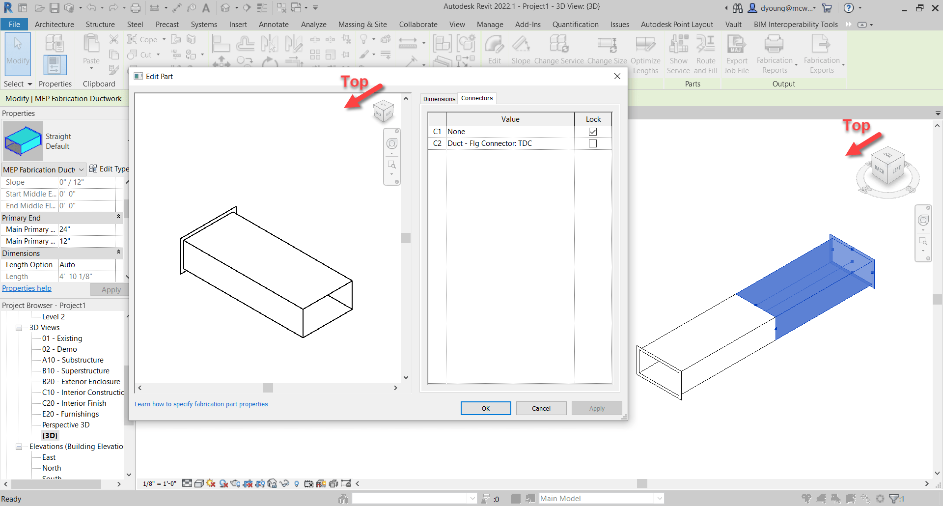
Duct/Pipe mirrored in Revit matches the editor when View Cubes are aligned. Selected Connector highlights.
This method is almost fool proof and has a few benefits over the sloped method we showed earlier.
Works on Fittings in addition to Straight Duct/Pipe.
Slope direction doesn’t matter.
But we did say Almost. Where this method fails, is if the View in Revit is redefined.
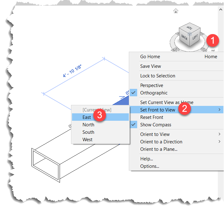
When you set a new Front View, the view in Revit no longer matches the orientation in the Part Editor window as seen in the following image…
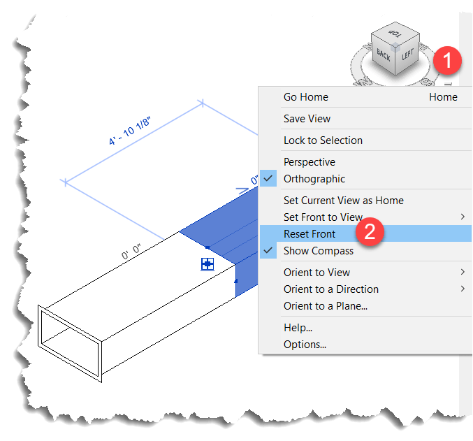
Luckily, this is easily remedied by simply resetting the Front View in Revit.
This method also works in Plan and Elevation Views with a slight twist. There’s no View Cube in the Revit window so it’s up to you to understand which viewing angle Revit is in. Next, you can make the View in the Item Editor match but when you look at a connector straight at the edge, you don’t see it highlight. You can then hold the SHIFT key and use the Middle-Mouse Button to slightly rotate the view so that you can see the connector that’s highlighted.
Here you can see what that looks like…
Summary
While not as quick and efficient as hovering over a connector in CADmep, either of these methods or even used in combination can increase your odds of changing the Correct connector on the first try.
While method #2 is more fool proof than method #1, there’s a reason I explain both and here’s how I’d use them both.
For non-sloped systems, the chances the slope symbol is reversed is very low. Because you’re likely selecting the part anyway to edit a connector, a quick glance is all you need to know which connector to change. Quick and easy for straight part on non-sloped fittings. No fuss. No muss. In this scenario, Method #1 is super quick.
For fittings and sloped systems, I would then shift to Method #2. Take a little more time, but it’s certainly quicker than being wrong 1/2 the time and then undoing the connector you just changed and then changing the other. That “trial and error” method results in 3 connector changes when you guess wrong. This is where Method #2 really shines…you get it right every time. If you’re Front View happens to be redefined, it’s easily rest.
Thanks again to Liz Fong (MacDonald-Miller) and Alina Y (JH Kelly) for their great input in coming up with these methods. They’re two of my favorite “Go To” people when I get stumped or need a little help orienting my thoughts.
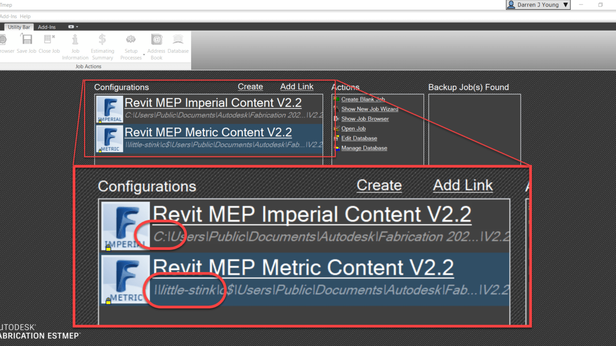
If you use UNC pathing to get to your Autodesk Fabrication Database, you might find issues when trying to create Profiles if you use them. UNC pathing or (Universal Naming Convention) is where you specify a server and share vs a drive letter. You can see below, the Metric Autodesk Fabrication Configurations is using a UNC path…
When using this configuration, you can create a profile from the File drop down menu in ESTmep and CAMduct or by typing MAPPROFILES in CADmep.
Creating New Profiles
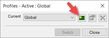
You go to create a new profile by clicking the Green button.
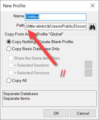
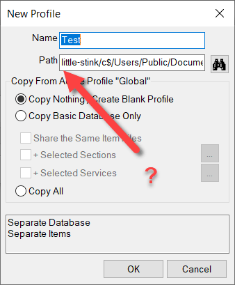
From here, the New Profile dialog starts with the default name “Untitled”. Notice also, the double leading forward slashes before the server name in the UNC path. (Yes, ‘little-stink’ is the server name)
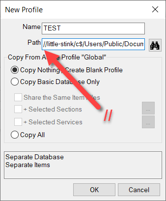
When you start to type a profile name, the leading forward slashes get stripped. This is likely a bug. You can see that in the following image…
If you click the OK you’ll get an error that the profile can’t create the required folder.
However, the fix is easy. If you just add the leading forward slashes again, you” be able to create the profile.
It may be easier to see from a video. You can watch the process here…
One of the things that can make machine setup difficult in CAMduct is setting up the coordinate system. This coordinate system must reflect the actual configuration of the machine. Some machines can be reconfigured to swap the axes or set the origin to any corner. This lets you configure the machine to match the software. Others can’t be reconfigured and require you to configure the software to the machine.
It doesn’t really matter where the origin is on the machine, just as long as the configuration in CAMduct matches. Matching the machine isn’t difficult, just as long as you understand what’s happening.
Default Origin and Axis Orientation
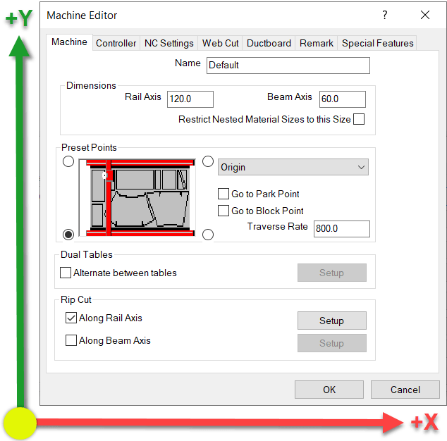
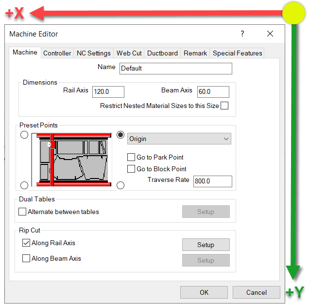
In the Machine Setup Dialog, the default Origin is in the lower left. Take a look at the settings and note the X-Axis and Y-Axis directions.
From this configuration, here’s a simulation of the code that’s generated.
If this configuration doesn’t work for your machine, it typically means the machine has a different origin and/or Axis configuration.
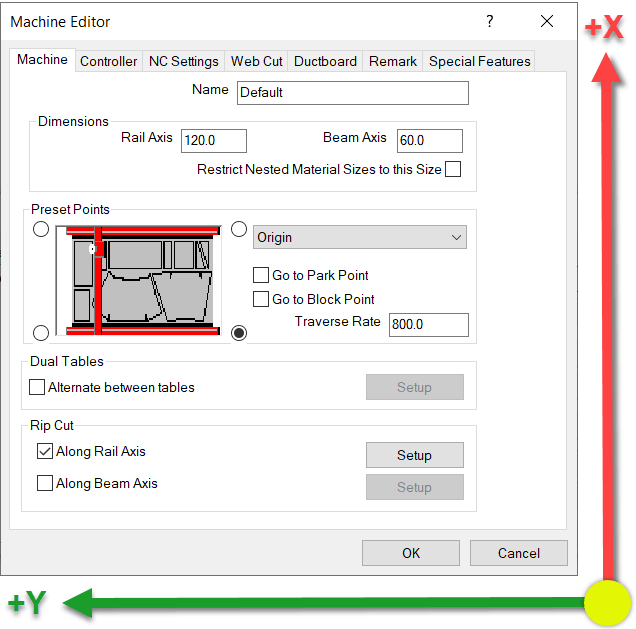
This next configuration rotates the coordinates which results of the X-Axis and Y-Axis being swapped. It also looks like the Origin location changes given the picture, but that’s not the case. This is why Machine Setup can be confusing. This picture does NOT change the origin location. This will become clear shortly.
With this configuration, you’ve now rotated the Coordinate System. When you look at the Simulation below, you’ll that the origin doesn’t actually move. The sheet is still oriented the same way. Long direction is the Rail and the Short direction is the Beam.
What you’ll notice here when looking at the code, is that the Part is Still oriented in the Lower Left Corner of the sheet. However, the X-Axis and Y-Axis are swapped. Additionally, looking at the code on the right, you’ll see how the Y-Axis goes into Negative coordinates. This also isn’t what most machines want, they typically work in positive coordinates but this is easily fixed which we’ll show a little later.
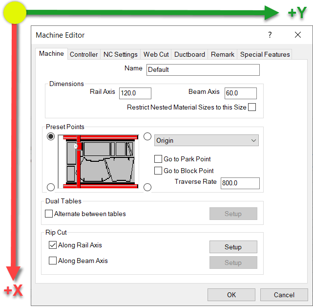
This next configuration sets the X-Axis and Y-Axis so that both are mirrored…or rotated 180 degrees.
Looking at the simulation of this configuration, you’ll see both X & Y Axes are using negative coordinates.
Here the both Axes are in negative coordinates and the Part is still located in the lower left of the sheet. Again, not what a machine wants typically, but easily fixed and covered in a little bit.
Here’s the last configuration. Again notice which way the Axes are oriented.
In this next configuration, the X-Axis and Y-Axis are reversed like before. But this time, the X-Axis is in negative coordinates where as the Y-Axis is in positive coordinates.
Fixing Negative Coordinates
What makes this hard, is that the setting in the dialog makes you think you’re moving the origin of the code. You are not. You’re merely rotating the coordinate system. This is critical when using a machine tool like a Lockformer or Vulcan that uses Trimble’s TookShop controller (formerly called Vulcan). Those are a couple of the most common machines where the X & Y Axis are reversed.
When you look at the simulations, the sheet is still oriented in the same location and the part starts in the same location on the sheet.
You can look at the configuration and see that the Rail is set to the long direction and the Beam is set to the Short setting. Remember this….it’ll be important in just a bit.
For this example, we’ll again use the 90 Degree rotated configuration (our second example) where the X & Y are reversed and the Y-Axis coordinates are negative. You can see in the code, that the Y-Axis is the LONG sheet dimension due to the rip cut along the Rail that’s cut at the end of the program.
Because the Rail Rip Cut starts at Y=0.0 and goes to Y-120.0, you can see that the Origin is still on the left side of the sheet not the right as the configuration screen suggests. Here’s a reminder of the Axis directions…
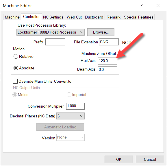
So if cutting the Rip Cut on the sheet from Left to Right for 120 units means the coordinates go negative, it’s clear the Origin is on the left. To make those coordinates go positive, you need to shift the Origin to the right on the Beam (Y-Axis). You can do this on the Controller tab and entering the shift amount for the Rail.
How, when you run a simulation on this setup, you’ll see the Y-Axis is still the long sheet direction, but they’re all positive coordinates.
Notice on the simulation that the part is STILL on the left side of the sheet and because we shifted the Origin to the right side the Rip cut along the Rail (long side) goes from Y=120.0 to Y=0.0.
You’ve now successfully swapped the X&Y Axis and corrected the coordinates to they’re all in positive units. From here, you can go back and finish configuring all your other preferences like where the parts get nested on the sheet, starting cut location, etc.
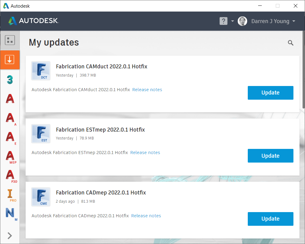
It’s recommended NOT to install this update for CAMduct or ESTmep. Installing the 2022.0.1 Update will prevent access to the Projects folder. CADmep does not appear to have issues with this update.
It’s been a long time, but Autodesk finally released an update to Autodesk Fabrication. 2022.0.1 Update was released recently and contains several fixes for 2022 versions of CADmep, CAMduct and ESTmep.
Install from the Autodesk Desktop App or download from your Autodesk Account portal (https://manage.autodesk.com)
Your services should not have broken links to ITM’s. Not only is it sloppy database management, it can slow performance of your database.
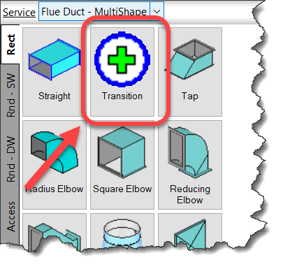
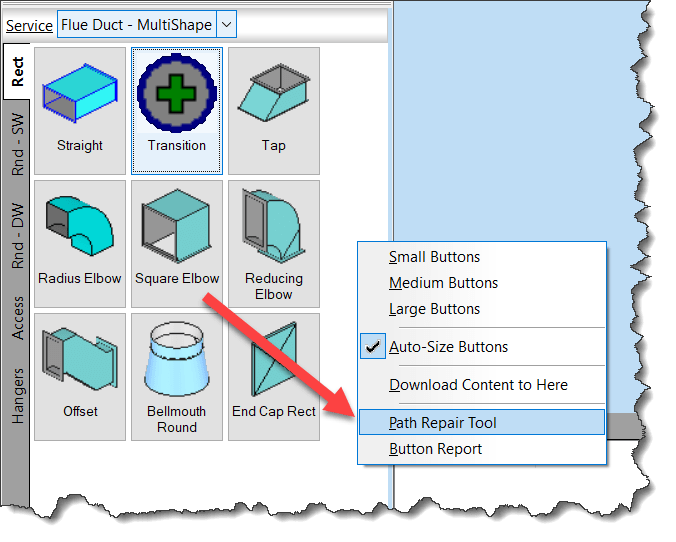
Use the Path Repair Tool to find (and fix) broken links in your services.
Right-Click and empty area of your Service Palette and select Path Repair Tool.
When you run the Path Repair Tool you’ll be asked to select a mapping file. You can click cancel and the tool will continue on. When it’s done, you’ll have a list of broken paths copied to the Windows Clipboard that you can paste into a file.
From this file, you can then create a mapping file. The mapping file is merely a text file in the format….
OLD PATH/NAME,NEW PATH/NAME
So the data you paste from the clipboard is good starting point, it lists all the broken paths. There may be duplicate paths listed if the path is used in multiple service templates. It’s ok to remove the duplicates.
Simply ass a comma after the broken path name and enter the new, corrected path. Once done, you can save the file and use it when you run Path Repair Tool again. It’ll then go and fix all those broken paths.
NOTE: This repair technique does NOT work if you have commas in your folder or file names. (See Best Practice #11)
I’ve added graphics to better illustrate the Autodesk Fabrication Object Model for COD Scripting,
If you write COD scripts for CADmep, ESTmep or CAMduct, this can help you better understand how the various properties and objects are structured when you write your code.
If you want to learn more about Fabrication COD Scripting and how to use these resources, register for MEP Force 2021 and look for my Fabrication Scripting sessions.
You can find links with the other Fabrication COD Language Reference items here…
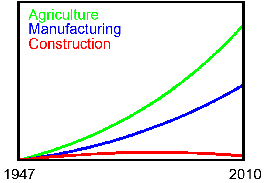
Most in the construction industry is familiar with the report from McKinsey a few years past as well as others. The report outlines how Construction lags behind almost every other industry in terms of productivity. It looks something like this…
Shortly after Autodesk acquired PlanGrid was when I really started to get annoyed about these statistics. It was during an evening dinner hosted in Seattle for local construction industry leaders. Autodesk and PlanGrid were presenting their vision of the future together.
In attendance were competitors, trade partners, general contractors and owners from the all the firms you think of when you think Seattle construction. Generally speaking, it was a good meeting. That is until a particular Autodesk executive took his turn at the microphone.
Like a well rehearsed orchestra, out comes the productivity chart with his statement that construction productivity has been flat for 20 years. Without skipping a beat, he informed the group that the ONLY explanation was that as contractors, we’ll “Work as Slow as you let them or as Fast as you Make them.“.
Anecdotal stories from industry trades men and women always made me suspect that data was misleading. Stories of how a 1 million sq/ft hospital use to be a 5 year project and now a good team can knock it out under a year. We’ve shifted a lot of work from the field to the shop and there’s really no benefit? Nonsense!
Sometimes when you start making improvements the benefits don’t first appear where you think. When you first turn on the A/C in a home in a warm humid climate, you start feeling more comfortable almost immediately. Except the first thing to lower is humidity, not temperature. Improvements in the construction process starting in the early 2000’s had benefits, they just may not have shown up in the poor metrics historically used to measure productivity. Similar trends were observed with technology in general. There was a lag between Silicon Valley tech’s offerings and results in business processes. It takes time to realign business ecosystems.
An Alternate View
My nature is to question everything and everyone. Even I don’t escape this scrutiny myself as I’m usually my toughest critic. I’ve encountered too many instances where reality was 180 degrees opposite of what was considered obvious.
While that McKinsey report was important for our industry, it’s also been very misused. Instead of the explanation being that we work as slow as allowed and as fast as we’re made to, I have another theory. The software we’ve been sold for 20+ years promising increased productivity and efficiency has done nothing.
To be fair, this story isn’t limited to Autodesk as plenty of other software vendors like to misuse this productivity data. I also don’t think technology has had zero benefit either. The debate on either side is largely hypothetical. Rather the problem is more complex and the description of the problem is also likely flawed in many ways.
What’s Behind The Numbers
The first place you need to look, is where do the numbers come from? McKinsey’s data comes from a number of sources including international. In the US, that data comes from the US Bureau of Labor Statistics. Only recently did the BLS start aggregating data from specific construction sectors. Those sectors are as follows…
Single Family Residential Construction
Multi-Family Residential Construction
Industrial Building Construction
Road and Bridge Construction
Prior to getting these more sector specific numbers, they simply applied productivity from Single Family construction to the entire construction sector as a whole. Data points simply weren’t available for anything better. The above sectors don’t accurately reflect much of commercial construction where software and services dominate the focus of sales efforts by vendors.
Simply put, we’re measuring a lot of different things. Measuring them poorly and lumping them all together to get a half-assed number. They’re not good numbers but they are better then nothing. Even the BLS talks about the difficulty in obtaining good data due to various factors. One such factor is that labor from subcontractors is NOT included in the data. It’s treated like purchased materials for the purposes of BLS data collection. Subcontractors were predominantly where early prefabrication occurred. Not at the general contractor level.
That begs to question, as we move more to product manufacturing in construction, does more of that dollar value shift out of the productivity stats? It doesn’t shift labor equally to the shop as there’s still onsite assembly needed. Much like outsourcing anything, it’s not a 100% shift in labor as there’s now project management involved when outsourcing so labor actually increases. I suspect a shift to industrialized construction will not show well using current productivity measurement methods. We’ve separated the manufacturing and assembly resulting in increased labor. How does this affect the numbers?
But don’t take my word for it, dig into the data and publications yourself. There’s some good reading.
While construction productivity is a story our industry needs to hear, we need you ensure the data is used within the proper context. To start with, those “Productivity Charts” don’t actually report “Productivity“. Rather, they report “Productivity Change“. Those are two vastly different things.
If you compared the most vs least productive activities against each other over time, one will likely show drastic improvements in one while the other shows little. That doesn’t mean the activity with little improvement is somehow the laggard or in drastic need of disruption. Simply put, some activities have more low hanging fruit than others.
Secondly, the nice things about charts is you can make them say anything. Looking at that earlier productivity chart, did Agriculture, Manufacturing and Construction all magically start out with equal productivity in 1947? Unlikely. Let’s look at that data in a complete reverse manner…
Same exact curves, but displayed differently. Is Construction a laggard or did Agriculture and Manufacturing just get their shit together finally?
Construction has so many variables and is so difficult to compare, that most of these charts compare against dollar value for lack of anything better. That is likely the best number to use as poor as it is, but Dollars to Hours ratios are not the same across trades, materials, geographic regions, construction types, etc. Nothing has perfectly equal economic value.
Don’t get me wrong. I’m not suggesting Construction is the lens that other industries should look at themselves through. Having transitioned from Manufacturing to Construction in 2008 myself, I see a lot we’re doing wrong and there’s dirty laundry everywhere. However when you look at the same data from a different perspective, it suggests that there’s more to the story. It’s not the picture much of the industry prognosticators and technology pundits suggest in an effort to peddle their wares.
Dissimilar Manufacturing Models
When you think of Manufacturing and increasing productivity what do you think of? High volume standard products? Or do you think of single individual custom products? Now how about construction? High volume standard buildings or custom?
Most of the world is made of standard products not custom. From milk cartons to dental tools to cars, most everything you use is a standardized product. If not, they’re assembled from standardized products. Productivity gains in manufacturing come from highly refined processes, assembly lines, standardized parts, simplification and automation. These things take significant overhead investment and volume to recoup the capital they require. There are millions of products on the market and each of those have a scale of units sold.
This isn’t really the case for construction. Construction is predominantly a large custom machine assembly activity. While there’s an increasing number of “products” going into a buildings, the ratio of standard products to custom will never be the same. Where a manufactured product requires custom parts, there’s usually a ‘volume’ component to the equation. And where there’s parts in a product, they’re assembled in similar or the same way in each unit. This also isn’t the case for construction now and never will be IMO. It’ll trend toward manufacturing, but the movement in that direction will always be less than the gap that still exists for much of commercial construction.
One last contrast between manufacturing models is at the task level. Much of manufacturing is automated or comprised of single person tasks. Contrast this to construction where due to size and scale, many tasks are performed using multiple people. It’s far easier to automate one person than an entire team.
Scope and Scale
Another key difference between manufacturing and construction is in the scale of the activity. In a nutshell the larger physically a product is and/or the more parts/complexity it contains the longer the cycle time. We can buy most any power hand tool with almost zero lead time. A major $250-500k machine tool like a 5-Axis mill is going to have a lead time from a few months to even a year or more depending on backlog.
A building is really just a large machine. Likely the largest machine that’s commonly built. And it’s complexity is likely only rivaled by products like a jet airliner. It should be noted that a 737 from order to delivery takes about 24 months and that’s a multiple unit production activity with a sometimes decades long design process.
One reason size matters is distance, Everything I need to assemble most products can be within an arm’s reach or done on an assembly line (multiple units). Have you considered the distances of material and workers in construction? Vertical transportation alone in a high rise is a significant factor in productivity. Same components…just higher up in the air. It’s not really fair to compare manufacturing productivity with the productivity of building a cross country highway. And when was the last time you’ve had the entire population of a city core commuting through your manufacturing facility while you’re moving materials into position? Does a factory floor material handler need oversize load permits? Coordinate a city street shutdown for a crane pick?
Complexity
If you look at the history of manufacturing, a lot of work has been outsourced globally. In the last 2 decades, a lot of that work has been brought back. With a focus on reducing complexity, ease of manufacturing and assemble (DfMA) manufactured products have become…simpler. Electronics and computers now replace complex mechanisms,
Construction on the other hand is trending in the other direction. Prefabrication and modularization takes added time and materials making things more complex. That complexity in manufacturing is a trade off for simplicity and safety in assembly on site…the actual build. It’s also what’s required to speed on-site construction and scale a physical location that can’t easily be scaled. It doesn’t in itself save time or material in many cases. It can actually increase these factors.
Simply put, product manufacturing used raw materials to make parts to make products. Construction used raw materials to make it’s product…little use of parts. Industrialized construction is inserting “product” into the process. That’s an extra step that didn’t exist before and productivity is not likely to be the first result you’re going to see. The benefits are elsewhere not productivity (quality, safety, scalability, speet of assembly/build, etc.)
In addition to prefab and modular trends, systems are more complex and new materials being developed in the name of energy efficiency and safety. With these systems comes significant financial risk. You could recall entire product lines and replace them for the price of a failed construction project like the Harmon Tower in Las Vegas. Do a quick internet search for the litigation around construction failures using Aquatherm piping in the US….a product that’s proven itself in other markets but was often misused during it’s entry to the US market. When you insert new risk, it’s going to cost money and/or time.
Customer Business Models
Everyone wants an iPhone. It’s trendy like many products. How many people want the same home or office? How many building owners even use their building the same way? Buildings aren’t bought the same way or using the same criteria as manufactured products. The financing isn’t even the same.
Value is defined by the customer and what they’re willing to pay for. For products, it’s typically reliability, utility, fashion and/or often price. In construction, those things are important too but there are other factors. Some of those other factors often cause waste in other areas like labor and materials which cast a dark shadow on productivity.
Lets examine a couple real world examples I’ve seen….
Example 1: Hospital construction schedule necessitates overtime. The following week, it’s layoffs and a complete shutdown. Why? The healthcare company wants to buy another chain and an open construction product on the books creates an obstacle for the bankers, accountants and lawyers. No worries, it’ll pick back up in 6 months. In the mean time, you have a huge hole in your schedule with no time to fill. 6 months from now, you’re already booked and the labor halls have empty benches. How’s your productivity now? Ultimately the customer did what made sound business sense for them but injected added cost and waste into the process.
Example 2: Your doing a tenant improvement (TI) project. There’s another team doing the Shell and Core. You could really make use of their tower crane but they’re going to demobilize. After all, they work for the developer who wants to take their money and move on. Again, sound business for the developer, but which costs time and productivity to the tenant’s TI.
No Waiting or Digitization Required
How many projects do you know where the construction schedule is ahead of the design schedule? All to common right? We don’t have time to wait while 100% of the design is finalized. We make calculated decisions based on risk of change and move forward. Construction has a low digitization rate and lacks sophisticated supply chains. In practical terms this means construction is VERY agile. That’s right…Analog IS Agile.
All those digital tools and integrated workflows. None of that is needed to build. All you need are People, Material and Tools. Simple materials and simple tools. And simply put, until recently, the technology did not exist to properly manage that volume of data is a collaborative way. The Cloud has really helped here but it’s use as a collaborative tool in construction is still in it’s infancy.
Economic Risk
Another key difference between construction and manufacturing is the economic risk. Factory expansions get canceled or accelerated. But there’s also market research into number of customers and many other factors. It’s easier to scale your plans up/down or outsource fabrication and still get a large portion of your desired value. In construction, your customer is typically buying 1 of something. Half a fence isn’t 50% effective so it’s scalability during economic uncertainty is less elastic. We might scale back quality of furniture or advanced systems for energy savings but the building will get built or not. There’s not a lot of in-between.
Construction is also the largest capital investment someone will make. In a short decade (2008-2018), we went from a “Labor shortage“, to “Never Have enough jobs again” to “Labor shortage“. That type of economic swing does not lend itself well to investment in construction. It also doesn’t help you invest in building an industrial complex for construction. Detroit’s automotive industry, with it’s existing infrastructure has almost went out of business more than once in my lifetime. There’s no significant workforce still building cars by hand.
Accelerate that business cycle from my 50 years of life to a decade. Trying to build a brand new infrastructure to support industrialized construction isn’t going to happen over night. Most think Katerra failed. I think it was a hell of a win. To do what they did at the scale they did for as long as it went on was impressive. But it was an anomaly at best. Likely only facilitated by undisciplined business evaluations by speculators looking for a unicorn. Financial gamesmanship allowed Katerra to do what they shouldn’t have been able given the timeline involved. They paid dearly for that gamble. The industry as a hole has benefited. Industry innovators and disruptors often only serve to break the dam. Others behind it are often the floodwaters you were expecting.
Different Social Engagement
Construction is also a very social activity. This repeats each and every time. Manufacturing on the other hand is social during design and perhaps production startup. Even then it’s still considerably less social. After design and process definition, manufacturing becomes very transactional. When’s the last building you saw go up that was on auto-pilot? I don’t see the consumers of the built environment purchasing transitionally as a rule of thumb outside a few narrow edge cases.
Additive manufacturing (3d Printing) is perhaps the best hope of an “Auto pilot” for construction. It’s the sexy new thing in all the trade media publications and news articles. But I’ve yet to see a mechanical room printed in 3d. I’ve not seen how they’ve 3d printed embedded conduit or voids for electrical. And I’ve not heard of any new record tall skyscraper built this way. When Boeing has the largest buildings on earth (by volume) to build a jet, imagine them larger to build a 40-story highrise and make those production facilities mobile. That’s what we’re up against.
Regulatory Differences
The last difference I’ll highlight is the regulatory environment construction operates under. Does the city council and their various committees dictate the size, quantity or color of the buttons on the machine you’re manufacturing? Do community groups protest the look of your products and demand that they have a similar feel as the rest of the products in your home?
Safety is another where the regulatory differences are striking. No industry is exempt. But they are targeted. Be it fishing, robotic cell design, chemical processing…there’s usually a limited scope to much of the regulations being pushed in the manufacturing space. In construction, those regulations sweep broadly across the whole industry. Much of this is insurance and litigation driven as well. In these cases, time is money and money wins. I’ve yet to buy a car and have a discussion with a dealer about bonding, lien wavers, or if my coverage will be OCIP or CCIP (Owner Controlled vs Contractor Controlled Insurance Plan). Financing a car is fairly straight forward. A building is not. Risk drives this and it will affect productivity.
I’m certainly not disputing the value of safety. However every moment you’re setting up/taking down safety gear and not holding a pipe is increased labor cost. In a manufacturing world, those measures tend to be more permanent, not repetitively relocated. They’re also more easily automated in manufacturing if human waste can’t be extracted any other way.
That’s a Wrap
Again, the point of all this isn’t that I think Construction don’t need to improve or change. It does. Safety is critical. So is energy and material usage. The point I’m trying to make is this….We don’t need to be brow beat into buying anyone’s product. None of them are going to save our industry by themselves. Our industry is doing quite well and is headed in the right direction. It just takes time to change an industry and build and new industrial complex to feed it.
I hope the next time you hear someone casually throwing out construction productivity stats, you’re more likely to push back. Empty slogans and catch phrases have no place in disrupting our industry. Sound business and data driven decisions do. Don’t let them bull shit you any more.
A bit if Personal History
PS: The below photo is of my child hood home I moved into in 4th grade. It was built in 1975 in a rural part of Michigan with a county population less than 8500 residents. It was a prefabricated home. All floor plates, walls and roof trusses were delivered in 3 open top semi trailers and assembled via crane over a full concrete block foundation in the course of a day. That was 45 years ago and it’s still not mainstream today. Things change slower than you realize and only to appear to have changed quickly in hindsight. Industry disruptors rarely destroy entire industries overnight. While there’s a lot of runway ahead, if you objectively look back 10-15 years, you’ll see we’ve come a hell of a long way.
If you’ve not downloaded the Autodesk Fabrication Script Libraries lately, you might want to grab an updated copy. There’s been several updates over the last month. Here’s what’s changed…
DamperRotation Property (undocumented) has been added to all Debug, Job and Library scripts. Support for this property was added in 2017 but never documented. It’s there to support the rotation of Dampers on Fabrication Parts in Revit. It should be noted, that this value is Added to the Angle property of the assigned damper. As such, it acts as an Adjust and not an Override. e.g. Damper w/Angle of 90 + Rotation Property in the ITM of 90 results in a damper rotated 180 degrees.
StiffenerGroup Property added to the Autodesk Fabrication 2022.0 and later versions of the Debug, Job and Library scripts.
AirturnGroup Property added to the Autodesk Fabrication 2022.0 and later versions of the Debug, Job and Library scripts.
SplitterGroup Property added to the Autodesk Fabrication 2022.0 and later versions of the Debug, Job and Library scripts.
InsulationStatusLock Property added but listed as “Unavailable” as it stopped working in 2017. Added in the hopes it gets fixed in future versions.
StructureType Property added to the Autodesk Fabrication 2022.0 and later versions of the Debug, Job and Library scripts. Property was “Write Only” in 2021 and prior versions so was unable to display in prior versions.
Product ListHasCustomData Property has been added to all Debug, Job and Library scripts.
Product ListHasFlow Property has been added to all Debug, Job and Library scripts.
ItemPCFSKey Property has been added to all Debug, Job and Library scripts.
ItemCostByLength Property removed from Material Debug scripts (never really belonged there).
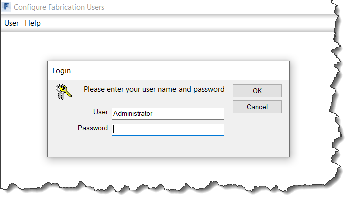
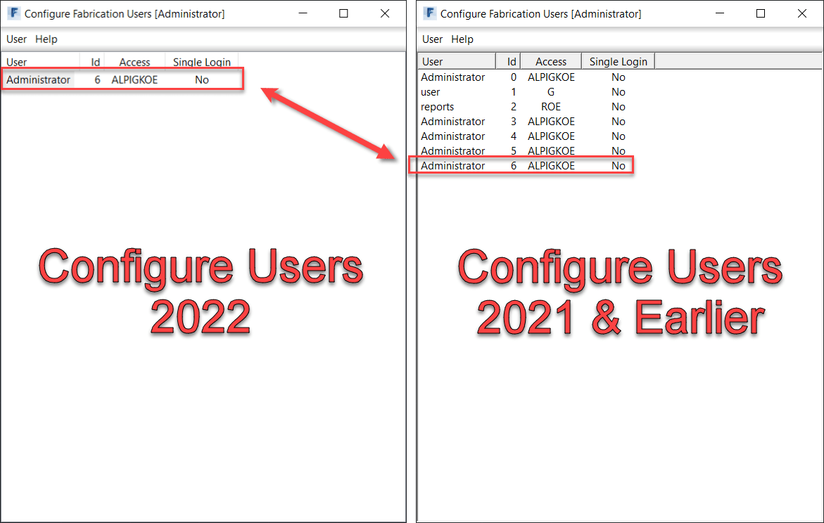
If you run Autodesk Fabrication as a multi-user installation, there’s a defect in the Configure Users utility. When you run the utility from a 2022 installation, it won’t read any of the user accounts you have configured.
In fact, the only way to login, is to use the Default Administrator account Autodesk uses if there are no users configured. It won’t read your Administrative account regardless of what the login is. To see the issue, you can use the following to login and see the problem…
User Name:AdministratorPassword:Admin
Once logged in, there will be one account. You can make more but when you exit and come back in, those accounts don’t show up. IN fact, even the original Administrator account isn’t there, it’ll make a new one. The following image shoes the users accounts that were created in 2022 be repeatedly going into it. Next to it is the 2021 utility showing those same accounts. As you can see, they are there, its just 2022 won’t show them.
Note that all the other Fabrication products will read/honor the accounts properly. It only seems to be the Configure Users utility that had the issue.
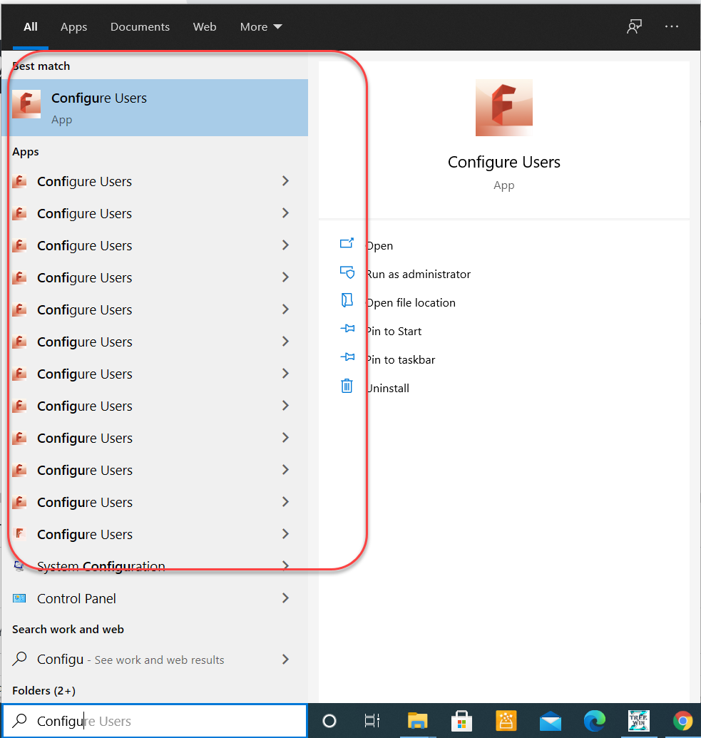
How to Determine Which Version of Configure Users To Run
To make things ‘easy’, Autodesk chose not to add the version in the name of the shortcut. Simply looking for ‘Configure Users‘ shows a lot of indeterminate results.
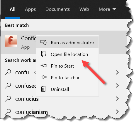
To pick a particular version, Right-Click on one of the shortcuts and select ‘Open file location‘.
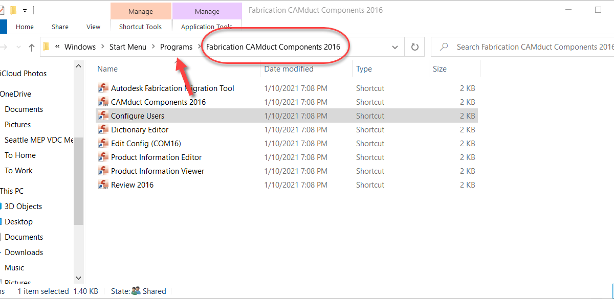
This will display a File Explorer window to the location of the shortcut you selected. As you can see below, the one I happened to pick was for CAMduct Components 2016. The product doesn’t matter, only the version, You can navigate back a folder then pick one of the Fabrication products for any version you want. 2021 and earlier will work.
Not sure if or when they’ll get around to fixing this. While 2022 has had a few issues fixed, they didn’t release any updates (yet) for 2021. Regardless if they fix it or not, it’s easy to work around by using any other version.
Does your fabrication shop lack confidence in your drafting/detailing department?
Have you struggled to get buy-in when trying to roll out new processes, technology or deliverables?
Did you wonder why? More importantly, do you KNOW why?
Getting to the Root of Trust Issues
My entire career spanning manufacturing to construction, fabrication shops have had trouble trusting the information they’re given. And there’s good reason. It takes time to master a domain and learn the work. And production staff are busy building and fabricating. They don’t have time to run into the office every time something is wrong. As a result, office staff take longer to train and often persist with producing lower quality work.
But there’s also a lot of reasons that are not good. Downright bad in fact because they’re simple to resolve. Things you’re NOT doing wrong but are causing problems. These trust issues are easily corrected if they’re understood properly. One such issue is fabrication tolerances that I categorize as Shop Math.
The Dynamic Between Tolerance and Rounding
I’ve had trouble explaining this verbally so I figured a more graphic (yet generic) representation would be in order. In basic terms, you need to use a rounding factor 1/2 the amount of your fabrication tolerance to achieve the desired result. As the title of this post suggests, a value of 1/100″ of an inch, can result in a deviation of 1/4″. That’s real Shop Math in practice.
My example uses both fractional inch and decimal to more clearly illustrate the point. You don’t want to get me started in why everyone should use decimal, that’s another post. But decimal also has the same dynamic, it’s just less hidden and more easily fixed. You get a lot less pushback in a shop by adding an extra decimal than by changing the denominator of a fraction to a number the shop says they don’t fabricate to.
Let’s take the following example..,
In this example, lets assume our tolerance is 1/8″ (construction field tolerances, that’s fairly common).
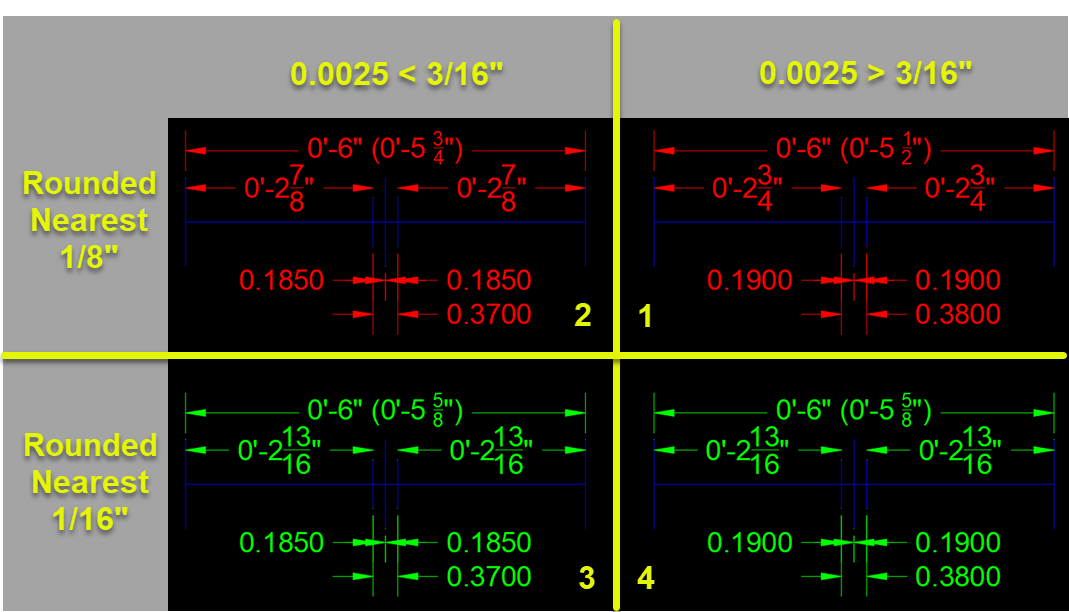
The TOP RED dimensions are all ROUNDED to the nearest 1/8″ to match our target Tolerance. A fairly common practice. The BOTTOM GREEN dimensions are all ROUNDED to the nearest 1/16″ which is half our target Tolerance.
Each graphic shows a line 6″ long. Half that is 3″. We’re going to make a gap and dimension from each end to that gap. Maybe it’s a weld joint in pipe or perhaps a mortar joint in concrete block. Doesn’t matter what to illustrate the problem.
For the graphics on the LEFT (Quadrants 2 & 3), the gap is just shy of 3/16″ of each side of middle to forced the dimension to round UP. For the graphics on the RIGHT (Quadrants 1 & 4), our gap just heavy of 3/16″ of middle to force the dimensions to round DOWN.
Rounding = Tolerance = Confusion = Mistrust
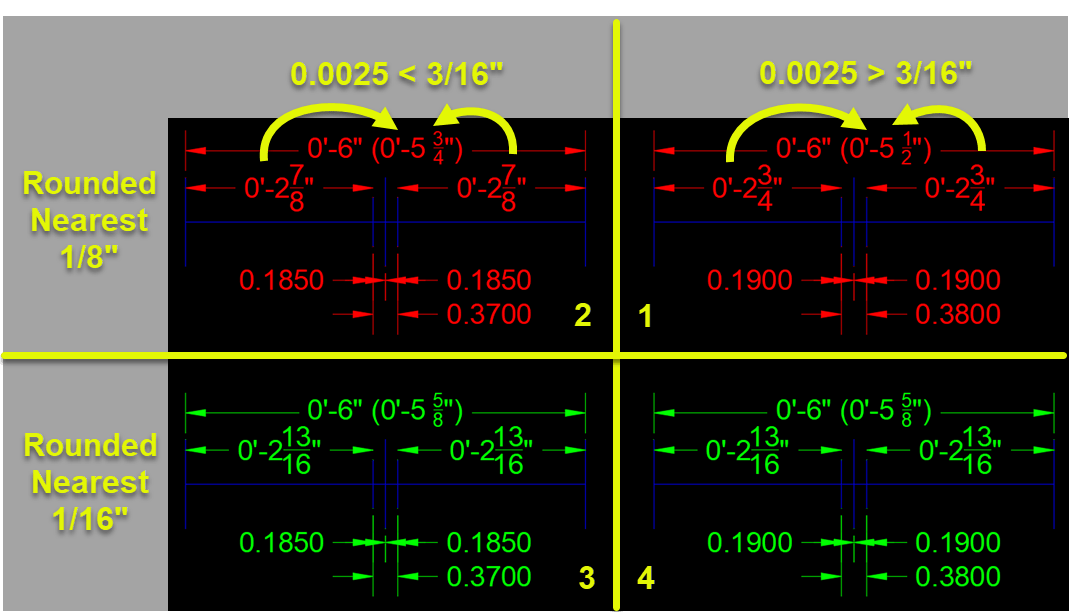
Let’s focus on the TOP RED in the following illustration…
If you take the two parts and add them, they vary by 1/4″. Adding 3/8″ (our rounded gap size) to either of them does not equal 6″ either.
Between these 2 examples, a mere 1/100″ difference in our gap results in a 1/4″ difference and neither adds up to the 6″ of the total length. This is a 1/4″ TOLERANCE because we set ROUNDING to 1/8″ to match our fabrication accuracy.
If you ever wondered why your shop doesn’t trust your drafting/detailing, this is one reason. The Shop Math just doesn’t add up. They see the sum doesn’t add up to the whole and leads them to question the accuracy of your drawing and your staff.
Rounding = 1/2 Tolerance = Trust
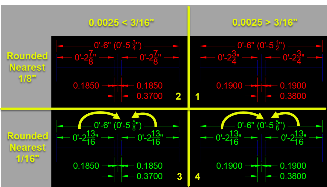
Now lets focus on the BOTTOM GREEN portion of our illustration…
Between the left and right (Quadrants 3 & 4) we’re still making the gap just shy and just heavy of 3/16″ from the center. As you recall, we said our fabrication tolerance target was 1/8″ but here, the dimensions are ROUNDED to 1/16″. This is HALF of our target fabrication Tolerance.
Here, it doesn’t matter of the dimensions round UP or DOWN due to the slight variation in the gap, the dimension are the same. Furthermore, if you add the parts, you get 6″.
As you can see, we had different results between rounding UP and DOWN when our ROUNDING value equals the Tolerance we’re trying to achieve. When we round to HALF the Tolerance, those small variations are masked and all our numbers add up.
So if you’re dimensioning for the shop, it’s important to realize this little change can mean questioning or trusting your data and staff. Additionally, if you take the time on the shop floor to explain WHY they see these differences, they quickly realize that the information that leads them to question the data (and your people), is also the very same data that’s most likely to be wrong. What IS accurate and didn’t change, is the geometry itself. This is an extremely critical point to highlight if you’re trying to get your shop to use automation and drive machine tools from CAD/BIM geometry.
The model/geometry, is the MOST right data we have. It’s just not human readable and what we provide as human readable is prone to errors such as these. This is one reason you’re seeing terms like “Model Based Enterprise” starting to float around in the Manufacturing space. It’s also a reason you’re seeing more shop go paperless, eliminating dimensions when possible by leveraging automation.
These efforts can be challenging and often require a leap of faith. But if everybody understands dynamics like this, it can be extremely helpful in moving all of your staff to more digital workflows. Because they trust the geometry and you eliminate what’s confusing them.