Autodesk’s Remote Entry can be installed on any number of computers without cost just as long as you have at least a single license of Fabrication CAMduct (~$1000/yr). You can read about Remote Entry’s licensing details here. Remote Entry is only of value if you’re shop or your duct manufacturer uses Autodesk’s Fabrication CAMduct to drive fabrication.
Note, like most of Autodesk’s Fabrication software…this is a stagnant product. Works only on Windows (no Andriod or IoS). Unless you’re already using CAMduct in your shop, there’s littererly very little reason to ever implement this software.
BuildCentrix
BuildCentrix started out as Webduct. They’ve since expended beyond ductwork and gone as far as having capabilities to integrate with a number of ERP systems. This is likely the best “Enterprise Class” tool focusedon ductwork at this time.
FieldOrderZ
One of the newer players in the market, it’s a project partnered with GTP. However you don’t need to be a GTP Stratus user to leverage FieldOrderZ. It can serve your needs even if you’re not a Stratus customer. It can also facilitate more than just Ductwork. Works best for Autodesk Fabrication users but I’d encourage you to reach out to them to see what they can do if you’re not an Autodesk Fabricatino customer. Likely one of the easiest tools for your Field staff to sketch what they need without being an AutocAD or Revit savvy detailer.
SiteTrace
SiteTrace is another newcomer I’ve just become aware of. CAD Content agnostic, it’ll help digitize your field ordering of Duct and related accessories saving you time and errors from traditional processes. They don’t integrate with any CAM software or Machine tools at this time making it the perfect fit for those smaller shops that get overlooked by the larger software companies.
Trimble FabShop
This is the old Vulcan software, one of the long timer CAM platforms for Duct fabricators. Their current platform has mobile capabilities that allow Field ordering of duct and processing within Trimble’s Shop Fabrication software.
Vicon Vi-Call
Most pepole know Vicon as a builder of Duct fabrication machinery. But they also offer a varierty of software tools. One of which facilities ordering of ductwork from your field staff to the shop into their managment platform.
If you’re aware of other field ordering tools for Sheetmetal ductwork, drop me a note and I’ll get them added to the list.
Paraphrasing Country singer Johnny Paycheck, “Take this Modeland Shove It.”
Yes. You heard me correctly. But just to be sure, let me rephrase it another way….”F_ck the Model“.
There. That should do it.
That may seem a bit of an odd thing to say. Especially for someone like me. After all, I’ve spent most of my career working with technology in Manufacturing and Construction. It’s been good to my family and I. But like many things, it can go too far. And it has. It’s time someone stands up and says something.
Why Do You Oppose 3d Models?
Why am I opposed to 3d models? Simply put, I’m not.
I’m opposed to idealistic visions of a utopia where everything can be solved with a 3d model. That may be the case one day, but it won’t be in my lifetime. Technology moves fast. But we’re also a long way off from promises made even a mere decade ago. The value of creating many 3d models does not overcome the cost to generate them (or maintain them).
There’s a lot of reasons NOT to model things. I won’t elaborate too deeply here. You’ll either get it or you won’t. But to summarize, here’s some of the major reasons to NOT 3d model something…
No time / schedule
No resources / staff
Lacking tools / technology
Less efficient / takes longer
No value / creates waste
If you disagree and think we should 3d model everything…like right now today, consider you might be part of the problem.
The 3d Model Vision
There’s a lot of folks who tell you how things “should be”. Digital Twin this and that. Everything will have a perfectly pristine working digital clone. Identical in every detail.
For the most part, I agree with them. However there’s an economic ecosystem at play. It’s beyond the control of a mere few wishful thinkers and prognosticators. It takes a while to turn around an industrial complex the size of constructon. So until modeling everything adds value offsetting it’s cost, some things (many things) should never be modeled. Ever.
Some will say this is because the industry full of laggards. Those reluctant to change. But look around. The skyscrapers, the roads and bridges, the dams and monuments. Do they look like they were constructed by laggards? Next time you’re in a big city, walk up to a construction worker and call them a laggard. See how that goes for you.
It’s also important to keep in mind how things “are” didn’t just happen in an ignorance vacuum. Things evolved for a reason. And until those reasons go away, we’re left with what “is” not “what should be”. And if things haven’t changed as you expected, consider the problem might by more complex than you give it credit. Those ‘laggards’ as they’re called, just might know something you don’t.
Resistance to Overboard
3d Modeling in manufacturing preceded common use in construction by about two decades. Same with concepts like PLM which is manufacturing’s ‘BIM’. Lean? Started in manufacturing (Just like me).
I pushed hard for 3d modeling back in one of my old companies. Endured the eye rolls and comments about how “3d is for boxes, not complex things like the warped surfaces” which they were doing in 2d AutoCAD. I also promoted Revit for a manufacturer of construction materials before Autodesk acquired the technology.
In each of those cases, when they finally saw what I was trying to convey, they over reacted and went too far. Complete abandonment of all 2d even where it made sense and 3d had no added value. They even attempted to do manufactured piece part modeling in Revit where Inventor or Solidworks was better suited. What was need was nuance and a blended approach. Instead the result was a binary shift. Classic throwing the baby out with the bath water. Lessons learned the hard way.
Sometimes when you apply too much force to a seemingly immovable or stuck object, it’ll eventually break free and go beyond it’s acceptable tolerance. If you’ve ever busted a knuckle trying to remove a stuck bolt while working on your car, you know what I mean.
3d Modeling has went that same way. Gone too far. If you ask me, as an industry are suffering from bruised, broken and bleeding knuckles.
The Problem With 3d Models
So what’s wrong with the current 3d modeling approach? Absolutely Everything.
No, not THAT ‘Everything’. There’s a lot of 3d modeling that creates incredible value and eliminates waste. It greatly exposes risk before cost is incured. In those cases we should do more not less.
The ‘Everything’ I’m talking about is that we’ve somehow moved into this unattainable, low intellect thinking that 3d modeling is the answer for….well, just about EVERYTHING. Revit projects have become nothing more than an erotic orgy of data vomit.
Oh look…corn. I don’t remember having corn. Is that a piece of baked potato? A date dump from a 3d model often results in forensics to even determine what the hell it is.
Need data? Add it to the model.
Nothing modeled? Model it.
Data changed? Open the Model and edit it.
Somehow the 3d Model turned into not only the single-source of truth but the ONLY source of truth. Merit for what to put in a model is typically controlled by somone with limited perspective. Can the computer can open it, navigate efficenetly and display/print sheets in an asthetically pleasing way? That’s the benchmark used today. There’s not a shred of data lifecycle cost or maintenance perspective let alone the cost and impact of those decisions up and down stream from the model.
This is absolutely flawed thinking. When you look at the data required for the built environment, there literally is no commercially available applications on the market today to help you manage this data. Hardly at the project level, and certainly not at the enterprise level. None. They’re all focused on the project model at it’s core….not project data. And certainly not enterprise data.
Yes, there are applications that help you manage portions of data or small genres of data. But nothing exists today which allows a company to manage their AEC ‘Data’ and leverage it across the enterprise. Once again I repeat, NOTHING.
Baseless Claim or Reality?
I’ve been thinking along these lines for some time. Years perhaps. I’ve been in User Groups and Meetups. Vendor Webinars. Industry Conferences. Hallway conversations. Far too many times I’ve heard “Model it” or ‘Add it to the Model”. No debate. No discussion. Just an accepted fact without any hint of value focused thought.
There’s a lot of examples in other industries that suggest alternate thinking. One is Manufacturing which typically leads trends in constriction by a couple decades. Manufacturing has Data Management systems and PLM (Product Lifecycle Management) systems. These are database systems that manage not only models but the data about the models. The key is that the data is associated to the model from an external database. They typically contain a lot of data that isn’t modeled. Anyone model Grease or Paint? A well implemented PLM system will tell you exactly how much you need and where to procure it all without a model of it.
Another notable example is GIS (Geographic Information Systems). A database is at it’s core, not CAD data. CAD data is merely just a small subset of data in a GIS system. Imagine a home changes owners. How does someone at the County get their GIS system updated? They update a database. What aren’t they doing? Opening CAD…Editing a graphical polygon with the owner information and saving the CAD file.
In both of these cases, external databases are linked to and help manage graphical models. The models don’t contain all of the data. And the databases usually contain MORE than just data for the models themselves. Unlike construction where we try to embed every conceivable piece of information right into the model itself.
I’m Not Alone…Anymore
As I said earlier, I’ve been thinking about this for a while. I frequently question my own sanity. Perhaps not as much as those who know me. But I do none the less. So imgine my surprise when I recently came across a couple articles that reaffirmed my thoughts.
This first is this article from AEC Magazine. ‘BIM is Bust’.
To summarize, enterprise data is locked inside applications (and models). It’s created there and those applications serve as the gate keeper. Yes there’s Cloud services with API’s. But the data they host and control is still application/model centric. It doesn’t integrate with your data. If you want the data, you have to integrate with it. As such, it’s application/model centric. Not enterprise centric.
How Should We Use Models?
By examining how modeling tools came to be, we can understand how those tools should be used,
That start was as a drafting and documentation tool. At it’s core, creating drawings is the act of working out design decisions and documenting them. That documentation is then used to physically build whatever it is you were designing.
As tools progressed, they offered some natural enhancements. 3d helped us visualize not just during the design process but for others who weren’t skilled at visualizing in 3d from a 2d document. Parametric functionality also helped us build smart objects which helped us quickly make derivative designs. These functions also helped increase efficiency in the design process. We lessened the need to calculate small details and merely used smart objects to help build a design. They’re really ‘Digital Pre-Fabrication’.
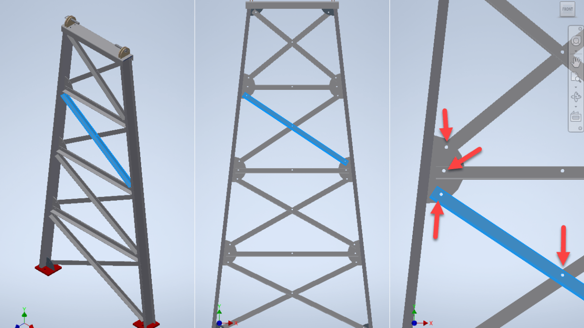
Here’s one example: The following image is a conveyor support. It’s top and bottom width are variable. So is it’s height and the number of cross bracing panels.
Now look at the holes on the half circular mounting plate. Look also at the holes where the cross-bracing meets. It’s not in the center. What’s the length of that steel angle anyway?
Imagine trying to calculate all of this information from purely numerical data and no geometry. It’s no small task. The number of right-triangles and trigonometry required is quite complex.
If you need to build a few of these, 3d modeling is the perfect fit. The smart objects have made it a digital measuring tool. But what if you fabricated thousands of these? All different. Copying design files and making derivatives with new sizes gets to be time consuming. And the same 5 or 6 inputs drive all of them. And eventually, some of the parts will likely be duplicate as parts from one design just “happen” to match another. And what if the design needs to change? All those models as opposed to just regenerating them.
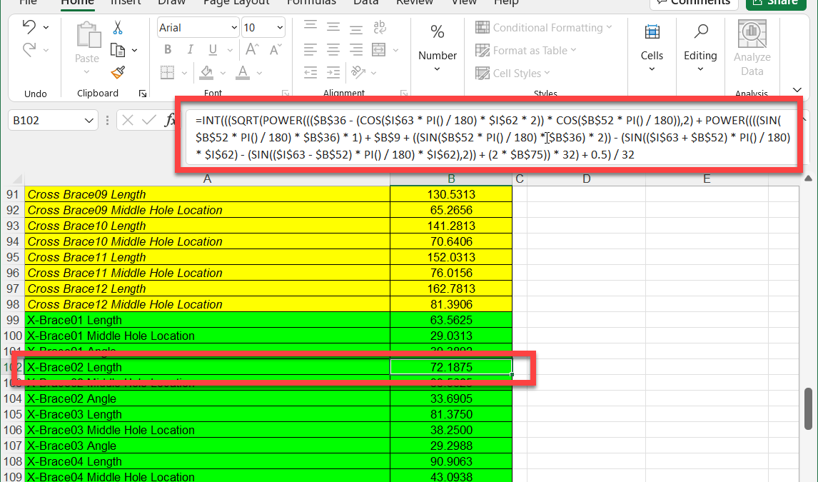
If you wanted to build a manufacturing system around this, you need a configurator and move data OUTSIDE the model. In this case, that’s what was done.
The assembly is 100% parametrically controlled from a spreadsheet. ALL data driving the model is driven from Excel from 6 inputs. From the length of the angle and position of holes. Even the size and shape of the structural steel shapes is driven from Excel. Here’s the formula for just the length of the selected cross-brace…
So what type of software tools do we have to manage this data at the enterprise level? Sure there’s product configurators but what about you parts library? Historical models and drawings? Common reference data defining shapes and configurations? Vendors and pricing? That’s where you implement data management or PLM systems in manufacturing.
What do we do with that data in Construction? Embed it in a model. Editable only by a Revit/AutoCAD/Microstation user. Locked up and application/model centric.
If you ask me, the solution was obvious. Or so I thought.
The Solution Should be Obvious
One of our technology vendors was pushed hard from many customers like us. The ask was to handle non-model based workflows and data. Their solution? A tool to model data in the field. They built some cool tech that will be helpful in cases, it’s not what was needed or asked. The data wasn’t modeled for a reason. So we didn’t need another tool to model it.
The real solution is to build a tool that can help us manufacture and build from data. No model required. Cutting of linear materials requires very little data as an example. Other operations like purchasing or assembly can be accomplished without a model too. Which means we can procure, manage pricing and labor, and even manufacture vast amounts of parts and data all without a model. None.
If we had tools that let us build WITHOUT a model, then where a model IS required it’s very simple to generate a model and/or link a model to that data. The manufacturing and construction process would have 100% coverage because it’s based on data, not a model.
When you use a model based system, you have partial coverage. You miss all non-modeled work and introduce a second workflow and processes. Also lost are analytics to view your entire operation.
One company I know literally publishes purchased items like buckets of adhesive as generic models. This is done so they can have all work go through their “model based” system and link to an ERP. Is that really what you want? It’s yet another workaround to compensate for lacking tools.
To summarize…
If you build tools that work only with models, they’ll only work with a model.
If you build tools that work with only data, they can also use models because a model is a shortut to data.
Now all we need is someone to start building “Data” centric tools.
Fabrication 2023 is out. I’ve updated all the reference information to include 2023 formats. As has been the trend the last few years, little has changed. Summary below…
I see a lot of people confused about how BIM360 Docs / Autodesk Docs works when used with BIM360 Design or BIM Collaborate Pro and Revit. It doesn’t help any that Autodesk repeatedly refers to ‘Single Source of Truth‘ as one of the benefits. While BIM360/ACC does help provide a ‘Single Source of Truth‘, it’s not quite as simple as it seems.
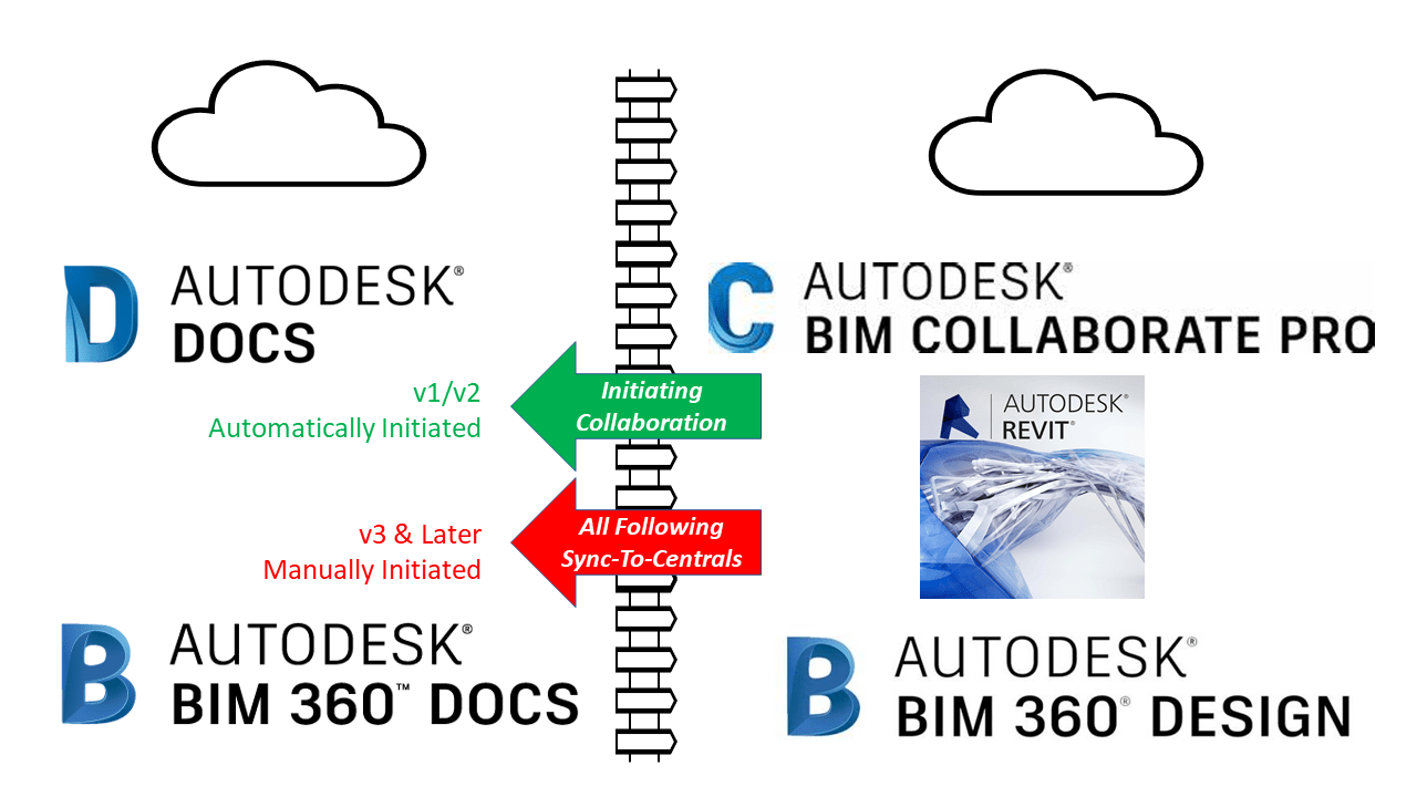
There’s 2 Models…Not 1.
Yes, you heard me right. There’s actually 2 models and a virtual ‘Fence‘ between them. One used by BIM360 Design / BIM Collaborate Pro and another completely separate model by BIM360 Docs / Autodesk Docs. This graphics might explain it a little better…
How Things Really Work
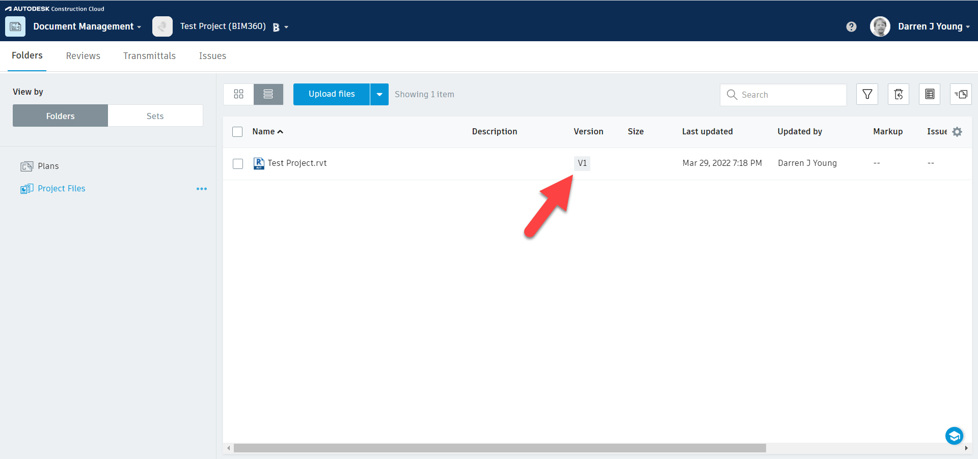
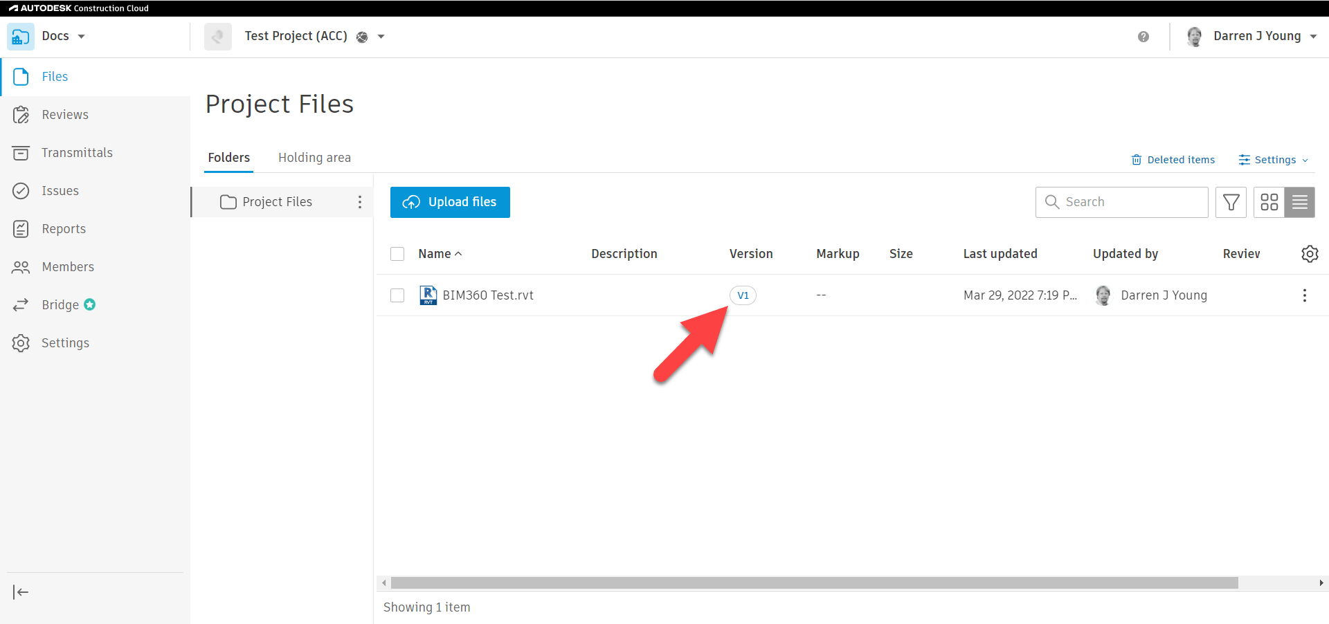
Before anyone creates anything, Docs has no files. The following images show BIM360 Docs on the feft and Autodesk Construction Cloud on the right. This will help you see subtle differences however things really work the same.
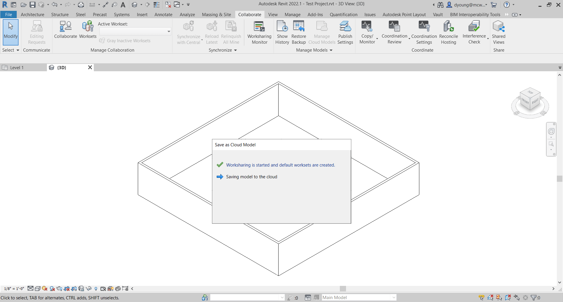
Next, you model something in Revit and Initiate Collaboration…
Once Collaboration to the Cloud is Complete, if you look at BIM360 Docs / Autodesk Docs quickly you’ll see the file shows up as Version 1 (v1). At this point, you can’t click on the file to view it. Autodesk’s system is merely creating a placeholder while it continues to process the model in the background.
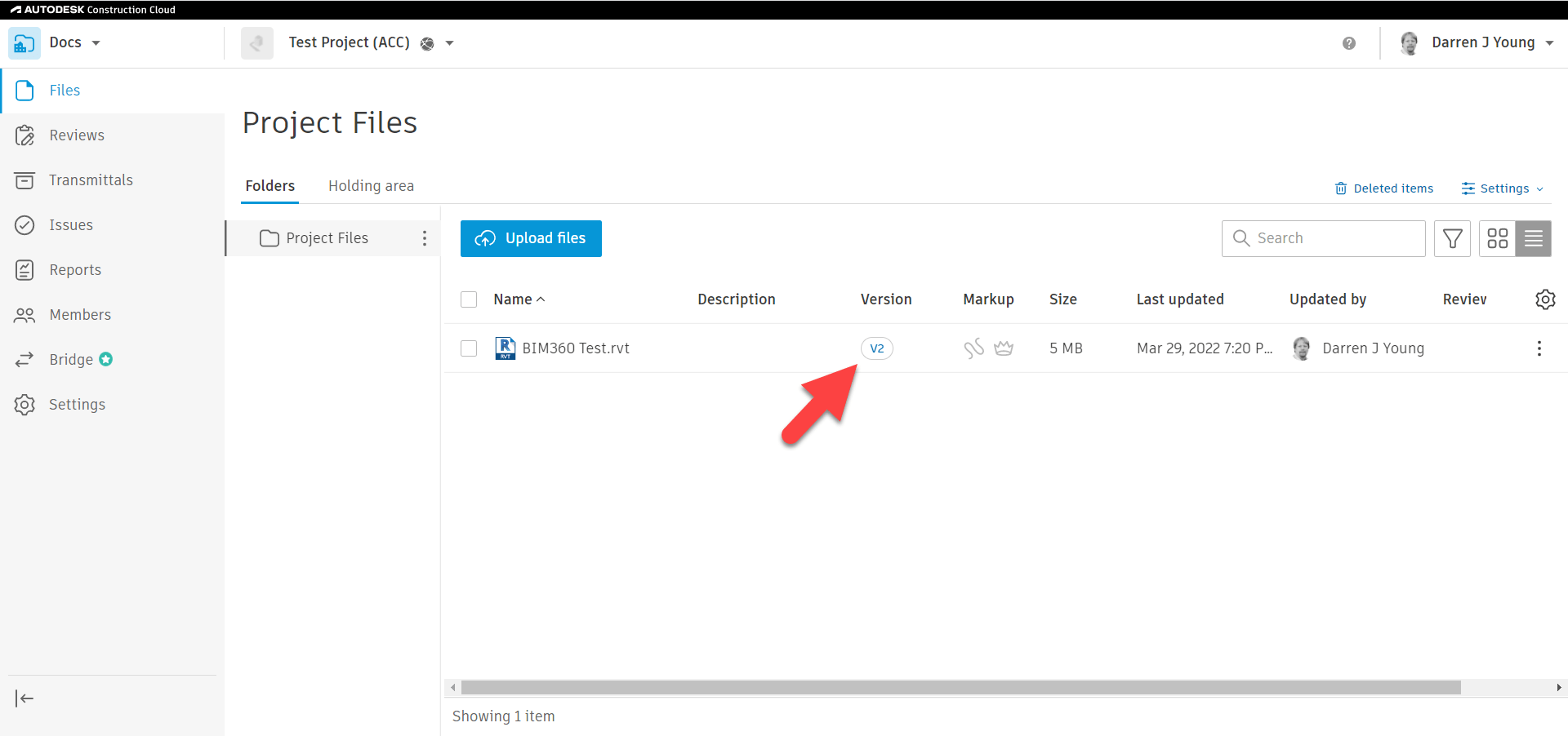
If you wait long enough, you’ll see that the files then update as Version 2 (v2). Once they’re listed as v2, they can be clicked and viewed in the Cloud. Despite saying v2, you really only initiated collaborate once from Revit. v1 was the initial file placeholder and v2 is the finished model that’s processed.
One reason for the confusion is that this v2 model shows up automatically. The common assumption is that it’s the same model as the one you opened in Revit. But that is NOT the case. The v2 model is actually a ‘Processed Copy‘ of the model you had open in Revit. That’s why it took a little while for the v2 model to show up in Docs.
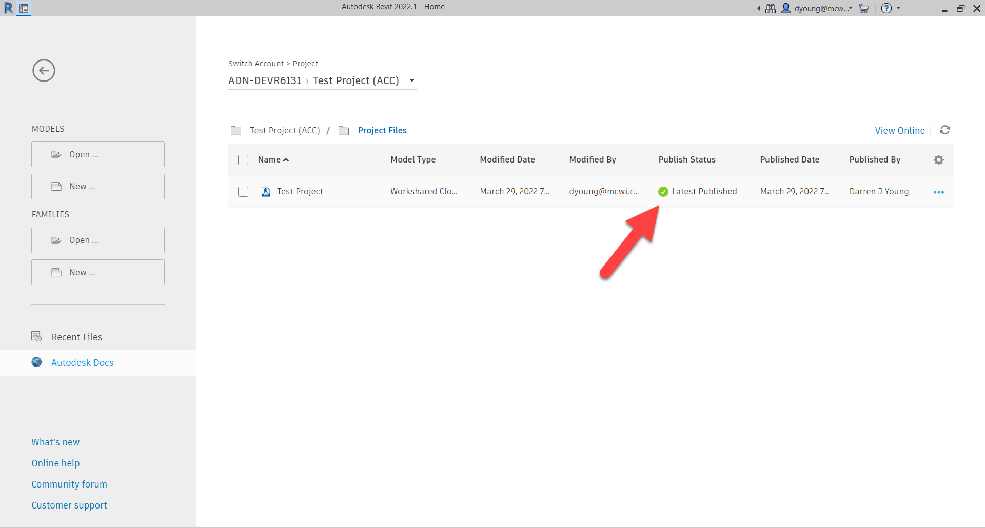
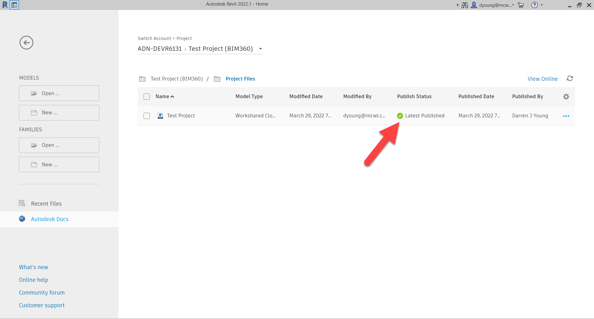
The next time you open the models in Revit, you can see that it shows the models as ‘Latest Published‘. Note that you should be opening the models through BIM360 Design / BIM Collaborate Pro and NOT from the Desktop Connector. More about that later. For now, you can see the models listed when you try to open them in Revit.
If you open these models, they would look exactly the same as those viewed from Docs on the Web. The next thing that happens is people change the model and Sync to Central. This will continue for the entire development of the model. Pretty normal stuff.
Despite syncing changes to the cloud, if you view the models from the web interface of Docs, they’ll still say v2 and show the original published model.
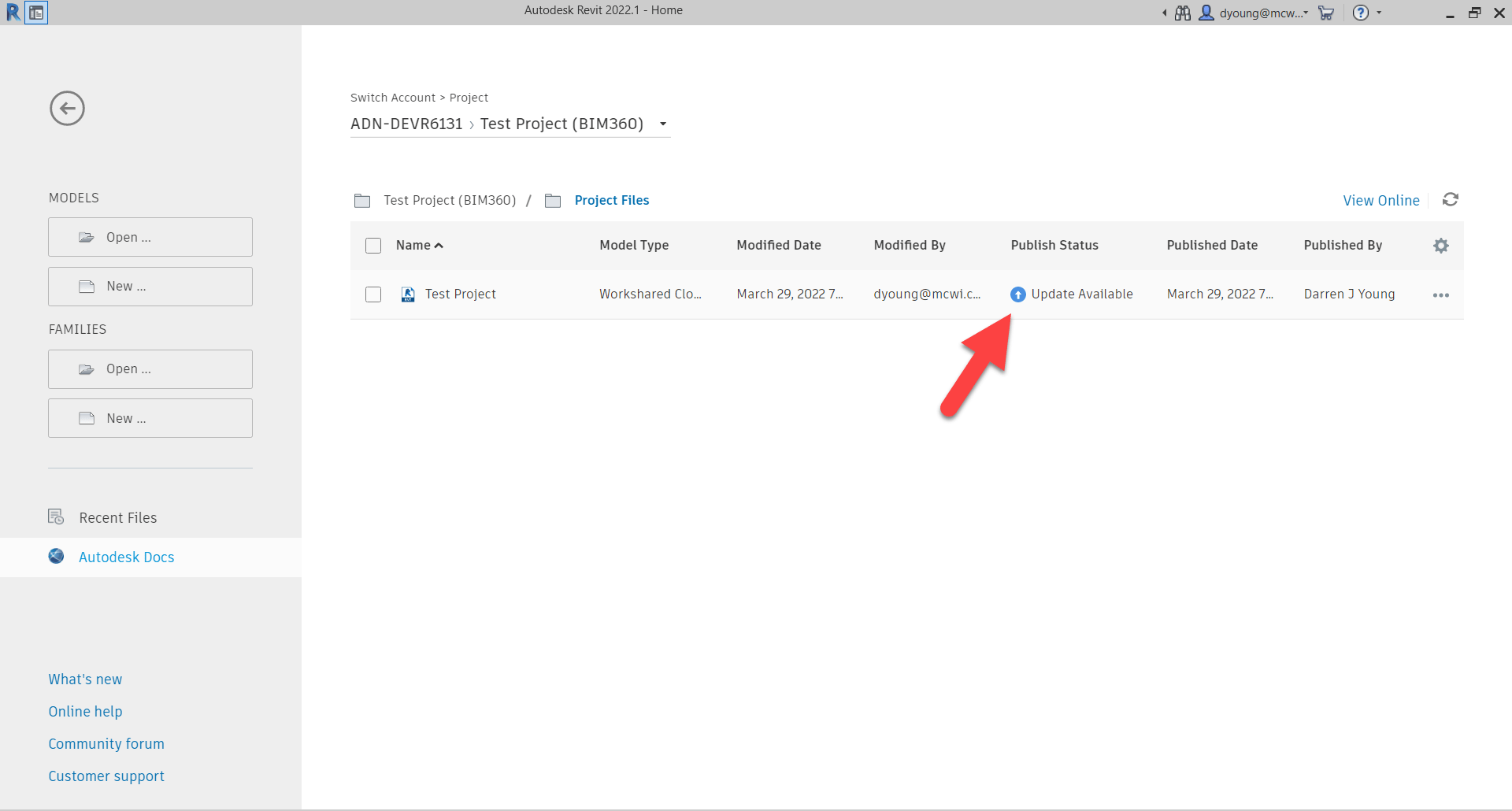
In fact, if you were to close and then try to reopen the model from Revit, you might notice that it now says there’s an ‘Update Available‘. Note: You might need to click the ‘Refresh the current project‘ icon in the upper right to refresh the status. If you haven’t browsed to a different folder/project or restarted Revit the project status cache might be stale and need the refresh.
When an update is available, YOU as the model author can choose when to push those changes to BIM360 Docs / Autodesk Docs. This is why there’s really ‘two sides‘ to models in BIM360. It’s intentionally this way to put you in control. You can control IF and/or WHEN to release your changes to the rest of your team for viewing. After all, you don’t want them to view your partial updates while you’re still working through issues.
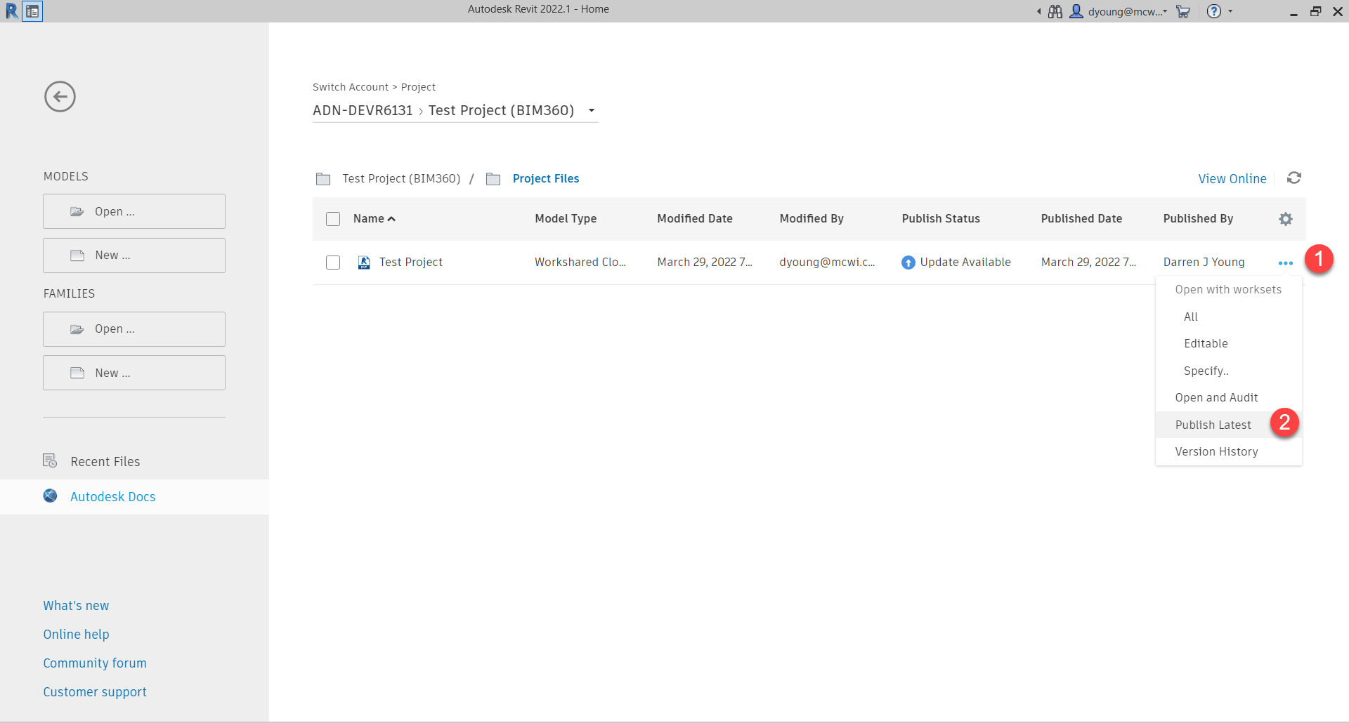
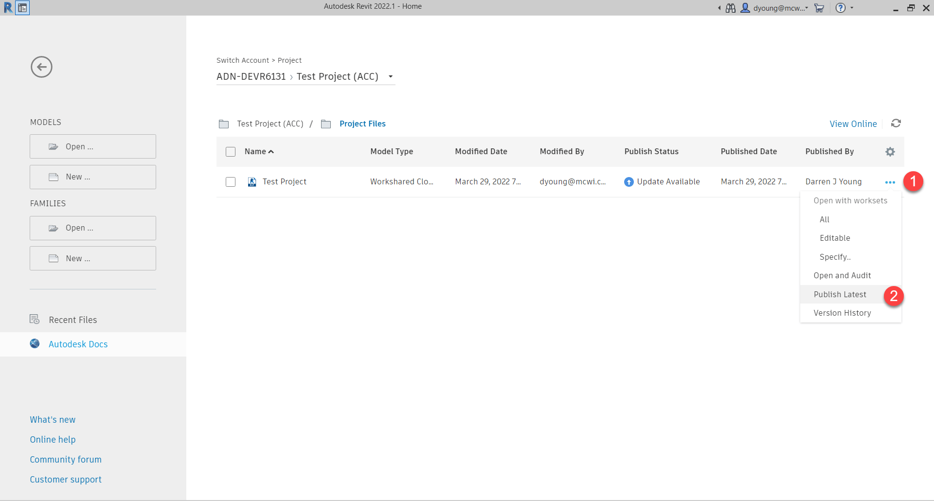
You can choose to update the models right from that same interface. Click the ellipsis button to the right of the file entry and select ‘Publish Latest‘.
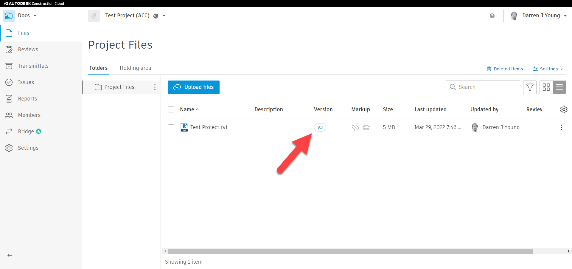
Once you select to publish the latest version, you’ll be prompted for a confirmation with some added details. You’ll then see the interface in Revit show it’s processing. Once it’s finished processing, you’ll be able to open the model again in Revit. If you look back at BIM360 Docs / Autodesk Docs once processing is done, you’ll see the file(s) there are now listed as Version 3 (v3)
At this point, your web view of the model in BIM360 Docs / Autodesk Docs is the same as when you open it in Revit. That is, until you make more changes and Sync to Central again. Once you have new sync’d changes, you’ll have to publish to Docs again. But only when you’re ready for the rest of the team to view the model.
BIM360 / Autodesk Desktop Connector Warning
It should be noted that the Desktop Connector displays what’s in BIM360 Docs / Autodesk Docs. It does NOT give you access to what you’re currently modeling in Revit with BIM360 Design / BIM Collaborate Pro. This may be perfectly well what you want when linking in a model from another team. But if you want their Live updates, you’ll want to Link from BIM360 Design / BIM Collaborate Pro.
Note that Design Collaboration does have advanced features for collaboration. It’s beyond the scope of this post but highly recommended you look into it.
I hope this helps you understand a little better about how BIM360 Docs / Autodesk Docs does and doesn’t relate to BIM360 Design / BIM Collaborate Pro. Just remember, it’s NOT the same model, it’s a published copy. The only time it shows up automatically in BIM360 Docs / Autodesk Docs is when you initiate collaboration for the first time in Revit. All other Sync to Central updates won’t show up in Docs without an intentional Publish by you or another team member.
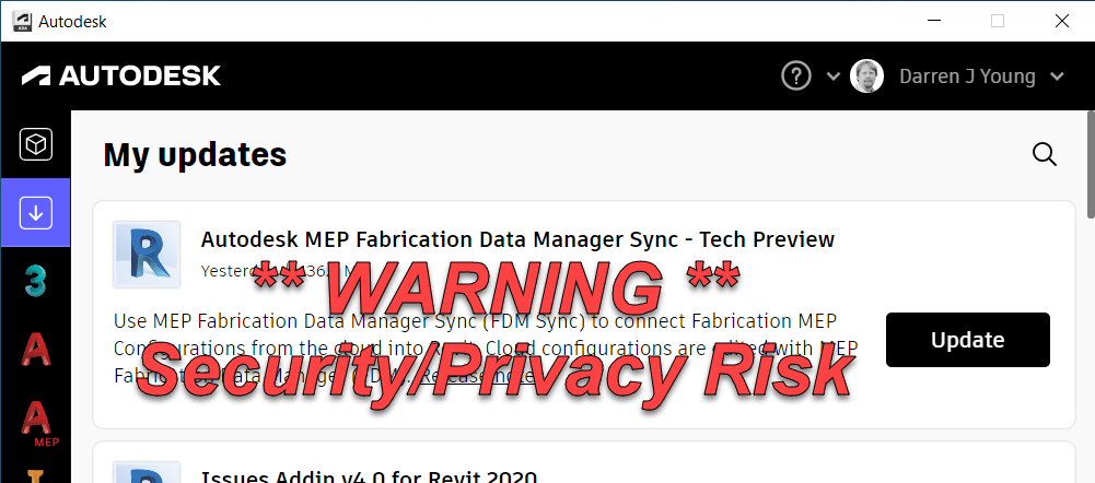
On March 23, 2022, Autodesk released the “MEP Fabrication Data Manager Sync – Technical Preview”. That same day, I posted to several sources a warning regarding a risk in using this tool. In this review, I’ll go over the risks shortcomings as I see them along with what background I can share that’s not covered under NDA. I’ll also address Autodesk’s public response to my warning.
What is the MEP Fabrication Data Manager Sync?
Let’s start with a little background. What is the MEP Fabrication Manager Sync? This is a tool designed to Sync your Autodesk Fabrication configuration from the Cloud to your local system.
But Configuration isn’t in the Cloud you may say. Well, that’s part of the plan too.
Why would we want to do that?
The Autodesk Fabrication configuration is complex and powerful but also fragile and bug ridden beast. Because of this it’s difficult for Autodesk to make changes and fixes. If you recall, in their last big restructuring, they terminated many of the developers who were customer advocates and knew the code. So attempting to advance just about anything it to the ‘Next Level’ risks injecting a LOT of defects into the products we use. If you’re a Fabrication user, you all know what I’m taking about. You’ve lived it.
Enter their ‘Cloud’ strategy to put the Configuration in the Cloud. There, they can put it in a safe environment, refactor it, rewire it and surround it with digital bubble wrap to product it’s integrity.
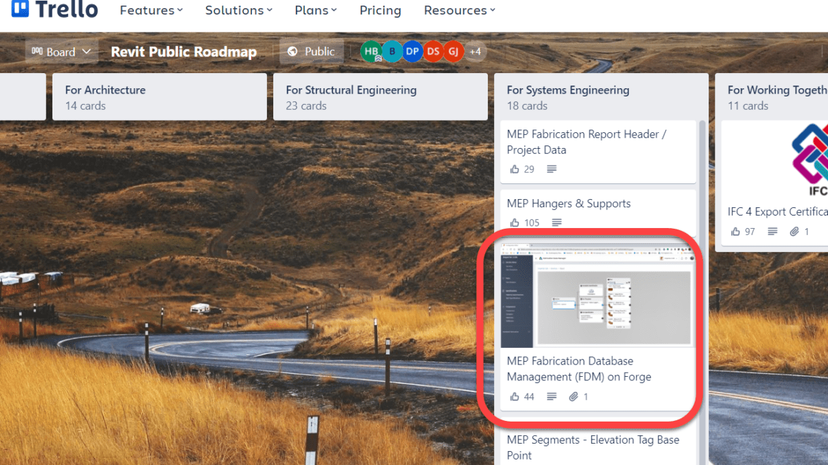
This has actually been on the “Public Revit Roadmap” for a long time. I believe it even predates the existence of the public roadmap.
This strategy is one reason why Revit Fabrication parts had had little added development other than token improvements since about 2018. Lets face it, if they were to build it from scratch today, they’d do it differently then it was 20 plus years ago when CADmep came out. Makes complete sense what they want to do.
But as anyone with even the slightest electrical charge in their skull knows, you can’t put the configuration in the Cloud and have a Desktop product access it and hope to have any shred of performance. Hence, the “sync” tool to pull it back down.
So to summarize, Autodesk’s Cloud strategy for Fabrication is to push it to the Cloud where it can be protected and enhanced but not used. And then they’ve built a tool to sync it back down locally for use in Revit only….for piping only….only for your company…only if you never need a new fitting…only if you don’t use ESTmep, CADmep or CAMduct.
What’s Wrong with FDM?
There’s a long list of things wrong with what was released. Here’s a high-level overview.
Major Issues and Limitations are NOT disclosed.
FDM is NOT Disclosed as “Beta” or “Not for Production”
Estimating/Labor data easily distributed to others with no ability to recall it.
Only a single “owner” of a configuration with no way to change the owner.
Anyone can easily upload your Configuration and use or share it with anyone.
No new Parts, Seams, Dampers, Stiffeners, Supports, Ancillaries, etc.
Once uploaded, no way to “Re-Upload”
No interoperability to CADmep, CAMduct or ESTmep
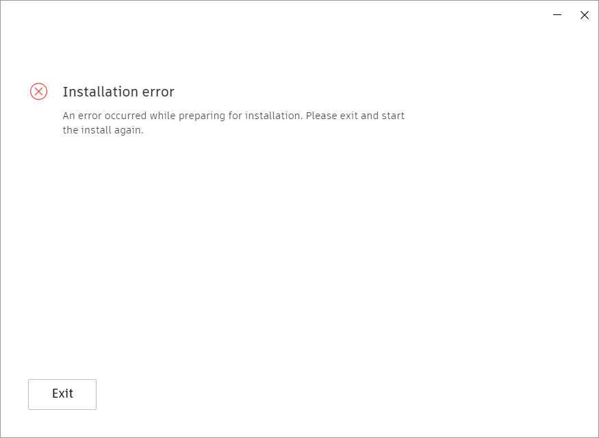
Install Errors
Limitation & Issues Disclosure
There’s a lot of limitations with FDM and the Sync tool. Do NOT make the assumption that their list of limitations and issues in the help file are in any way near complete or comprehensive. There’s so little covered that it makes it appear the problems are trivial. They are not. It’s embarrassing how little effort they put into documenting this. You really need to read everything and infer a lot based on what’s said and not said. This is the only way to get a full picture and use this product with minimal risk.
Is FDM a Beta or Complete Product?
You may have seen Autodesk product manager Martin Schmit’s response to my post that FDM and the Sync tool are Beta and shouldn’t be used in production. You can see them here…
The description in the Autodesk Desktop App does NOT say or mention ‘Beta’. So no, it’s not listed as a Beta here. Other Technical Previews in other products didn’t provide ‘Beta’ notices either of the ones I saw.
During install or once installed, review the ‘Terms of Service’ in the Sync Tool. It contains 2,709 characters / 501 words and not a single instance of the term ‘Beta’. Not listed as a beta here either.
The initial help file/Release Notes contained 14,290 characters / 2,698 words and again, not a single instance of the term ‘Beta’ in the initial release. In fact, under ‘What is a Technical Preview’ it stated the following…
“Tech Preview applications are considered complete and ready for use, but are made available on a preview basis so you can get early access before a broader rollout to all customers.”
It’s since been updated (likely because I called it out) to read…
“Tech Previews provide early access to pre-release or beta features for evaluation.”
But while it now contains a single ‘Beta’ term, it simply states that generically. A “Technical Preview” contains “pre-release” OR ‘Beta’ features. Nowhere in there does it state that this FDM is indeed a ‘Beta’.
The Blog Post also mentions that “Pre-release OR Beta” is what a ‘Technical Preview’ is and does NOT actually state that this is indeed beta. Merely that a Technical Preview may contain some Beta features. That’s a far cry from the entirety of the product being considered Beta.
There’s a link in the terms of service to Autodesk’s general ‘Terms of Service‘. That page contains 67,123 characters / 12,3871 words and contains the term ‘Beta’ merely once. Here in section 12 ‘Trial Versions’ the term ‘Beta’ is listed along “Not for Resale’, ‘Free’, ‘Evaluation’, ‘Trial’ and ‘Pre-Release’ terms. It’s a generic document that does not refer specifically to this Technical Preview. And it merely says that ‘Beta’ is one of many ‘Trial Versions’ that are governed under the ‘Trial Versions’ legal limitations. So yet again, it’s NOT listed as a beta here.
One of the YouTube videos linked the blog post mention using the Sync tool to distribute your database ‘Across Stakeholders’. This is not something you’d suggest for ‘Beta’ software or things you shouldn’t use in production. It implies collaboration…across stakeholders.
Am I being a bit picky? Perhaps. But the fact is that after 6-7 years of work on this, it’s still sloppy and incomplete. And unless you fully read everything and make a lot of conclusions based on interpretation and reading between the lines, the average user has no idea the risks they’re taking.
Where’s the Risk?
The risk is Autodesk’s repeated gross negligence in providing tools that expose your price and labor data. This is the 3rd avenue Autodesk has given users tools that provide easy access to your price and labor data. The other 2 avenues for this occurring still exist today with no acknowledgement from Autodesk.
Giving you a tool and telling you its to help you easily collaborate with users without generic sync tools implies you can collaborate with it. But if you add collaborators, you aren’t told that they have access to your cost and labor data. If you saw Autodesk’s public response to my initial post, you can see them hide behind the rather weak “you’re in complete control of sharing” statement.
I suppose you can give a powerful and dangerous tools to any unsuspecting person and them blame them for the carnage they create. But it would seem to me, any firm that is intent on being your partner would have a responsibility to disclose risks associated with the tools they provide.
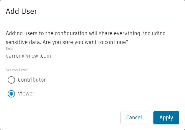
Here’s the only warning Autodesk provides…
A mere generic warning upon sharing is NOT enough. There’s no link to details or context. From a user’s perspective a generic message like that could merely be a blanket ‘CYA’ legal statement as virtually anything a user shares could be considered ‘Sensitive’. Further, take into account that the Web based FDM shows no Cost or Labor data, it doesn’t let you add or manipulate it. This would easily suggest to a user that Cost and Labor are NOT included. Especially considering their own documentation says Cost and Labor are ‘Future’ considerations.
FDM Configurations are downloaded to this location…
%userprofile%\AppData\Local\Autodesk\Fabrication
Browse within these folders and into the Databasefolder and you’ll see COST.MAP, FTIMES.MAP, ETIMES.MAP and SUPPLIER.MAP. Once shared with another user, the Configurations owner can NOT pull them back. All it takes is copying this database to a new location and add it to ESTmep and you’re Price and Labor data is hacked.
This is a Known Issue yet it’s not disclosed in the ‘Known Issues’.
Only One Owner
A Configuration can only have one owner. It also has no way to be changed without Autodesk’s back end assistance….maybe. Again, a limitation you’re not told of. If whoever manages your configuration leaves and you’re up a creek.
Any because Autodesk accounts are tied to Emails, they have full access to your configuration even after they’re gone. It’s yet another security risk for which YOU are not able to manage or control.
Easy End User Manipulation
Again, there’s no control you’re allowed for users. If you install this tool to your user’s system so they can consume a configuration you shared, they can upload and share it with anyone they want. Super easy and you’ll never know. Yes, they could always give your database to someone anyway, but it’s a very intentional act and requires some technical knowledge. This sync tool merely looks like an easy way to collaborate with little warning about what the consequences really are.
Database Coverage Limited
There’s not a lot you can so with FDM at this point. You can make new services, templates, materials and specifications. But you can’t copy an ITM or make a new one. You can’t edit the product list of an ITM. Can’t make Ancillaries, Kits, Dampers, Supports, Stiffeners, Notches. Support Specs, Service Types, etc. You can’t edit Labor or Price. You can’t edit service types, custom data, oval stretch outs, etc. So there’s not a hell of a lot you can do. You can’t really manage your database. Additionally, there’s no capability to bulk edit even those things you can edit in FDM. It’s certainly not going to be faster to edit your database. At best, trivial edits are allowed. Any other use is going to be burdensome.
No Way to ReUpload
Once you upload a configuration, you can make some limited changes there. But not everything. Everything else you need to edit in CADmep, ESTmep or CAMduct. And once you do, there’s no way to upload your changes. Your only option is to delete the Configuration on FDM and loose any changes you made there.
So now you have 2 independent vectors for editing your database. One partial (FDM) and one complete like you always have. And there’s no way to reconcile those.
Now Autodesk will tell you they’ll be adding more. But judging from how they’ve implemented Fabrication Parts in Revit, they’ll never finish it according to YOUR expectations. They’ll get it to where they’re happy and call it good.
No Fabrication Interoperability
There’s NO interoperability with CADmep, ESTmep or CAMduct. And there’s no plans to near as I can tell. Read what they’ve pushed out. Their sole focus is on Revit. If they get to Cost and Labor it’ll be under the assumption that Estimators will use Revit to quantify their estimates. I can’t imagine a world where a mechanical estimator will use Revit to take off estimates. Another stupid half baked idea.
To add insult to injury, Revit does not report ‘Node to Node Length’ in Reports…it doesn’t work. So Autodesk’s official solution is to export an MAJ and run your reports from there as outlined in this KB Article. So for products they don’t want to support, they seem to be the solution to everything wrong with Revit as well as FDM.
Install Errors
I’ve had far more systems produce install errors than those that actually install properly. They knew of the error I reported it before release.
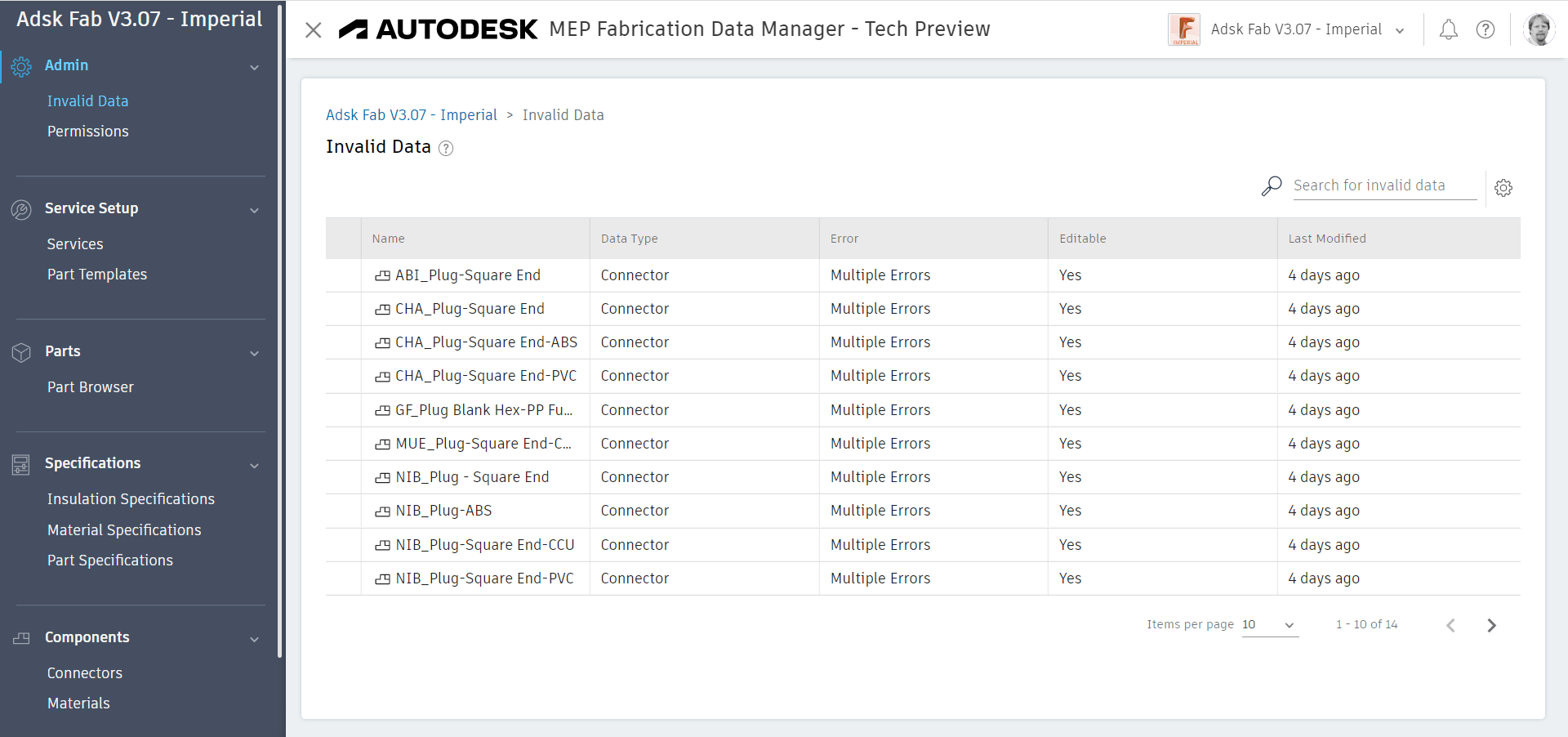
Well, a couple things. For starters, when you upload a configuration you can see the errors it contains. Ironically, they’re things that are perfectly allowed in Fabrication, just not FDM. You can use the Invalid Data portion to review the data errors. Autodesk’s own Configurations (all of them) are not even compliant as shown here…
One of the other good things about FDM is the ability to more easy visualize how your data is connected. Using their Relationship Manager you can see how your data is connected. This is good for new users as well as existing users who want to see things like which parts are connected to a material or connector or service template.
What else? Well, I can’t really think of anything. FDM is just not ready. And until you can edit your entire database in FDM, it can’t really be used. But that falls on deaf ears. They want input on what to “do next”. But that won’t increase usage. And if this takes another half decade, it’ll likely never get completed. That’s a LOT time in Autodesk years to have a project survive and get funding if it’s not used.
Summary
The Fabrication Database in the cloud has been done before. It was there and much more complete. I saw it. It was previewed at Autodesk University years ago. But it never saw the light of day. They killed it. It wasn’t built on Forge. So they did it again and built it on Forge. But Forge wasn’t ready or capable. So it took 6-7 years to get where we are today. Half assed and incomplete. A year into the project they said it would take another year. I told them it would be at least 5. I was wrong. It took longer. And it’s still not usable. It’s poorly documentation and so disjointed in their messaging that it risks your data.
They have no strategy or end game for how to work in EST or CAM. Now they want your input into what to do next. Except it’s obvious if they listened to everyone they ignored for the last 5 years. Their exclusively Revit based strategy has no promise for you any time soon. Worse yet, it lacks vision and doesn’t even strategically align with where Autodesk is going. That’s not just my opinion, it’s that of several insiders I’ve spoken with too. Their strategy is based on a 20 year old software called Revit.
So kick the tires if you like. But don’t install this garbage for anyone else. And for the love of God, don’t share your configuration with anyone else.
Lastly, if you want to know what you should or should not do with it, you can’t rely on the documentation. Apparently Autodesk’s official guidance and policy is buried in a single blog post per their response to me.
Autodesk Flex is Autodesk’s replacement for Network Licensing (FlexLM). Network licenses were supposed to go away a couple years ago. However Autodesk pushed back a lot of their plans and policies to make life a little bit easer when Covid hit.
While many customers had already been arm twisted into changing prior to the timeline extension, that offer still exists today. If you haven’t taken advantage of it, you will need to before it expires on your next renewal before Feb 7, 2024.
What is ‘Autodesk Flex’
Autodesk Flex is a ‘Token’ based system. Each product has a certain number of ‘Tokens’ it costs when you use them. Launching a product consumes that set amount of tokens and gives you access for the day to that product for that user on any computer. If you launch multiple products, each product will consume it’s daily tokens upon launch for that user.
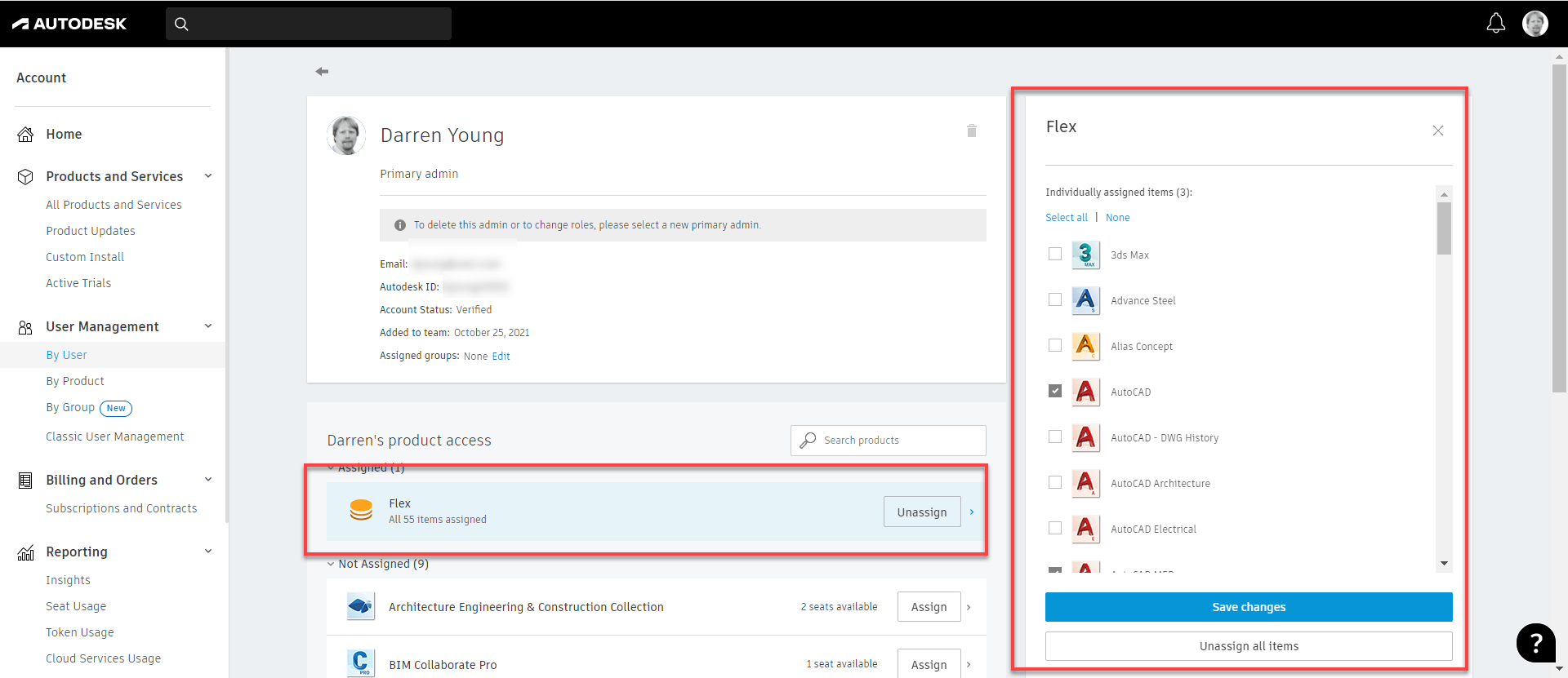
You assign ‘Flex’ to a user in the accounts portal just like any other product and it lets you run anything Flex has available.
You can also pick and choose which products you want to allow Flex to use if it’s helpful to not allow everything. An example would be that maybe a user needs Revit all the time, but Navis Manage only some of the time. You can give them a dedicated license of Revit and configure Flex to only be used for Navis.
(Note: This example is only if you have separate Navis and Revit licenses. AEC Collections come with both so this configuration isn’t valid in that scenario.)
Tokens are pre-purchased in set increments. They’re currently $3/token. Tokens will expire if unused for a year. You can add to your pool of tokens any time. Oldest tokens are automatically consumed first.
Autodesk has a token calculator that helps you estimate the number of tokens you need for a given product. That calculator is here…
You’ll see the cost difference between Flex and a dedicated Named Standalone license is about 85 days. If a user uses a product about 85 days a year, a Standalone Named User license is a better option.
When you get to Collections…it gets a little more difficult. Collections don’t have a Token rate so you’ll need to add the tokens for the products you use. The examples above are assuming you’re 2 products a day. You’ll see the cost benefit of Flex drops to 60 days. But it’s also more complicated…if you run three products one day and only one product another, the formula gets pretty complex. You’ll need to estimate how many times a user will use each product in the collection a year and add up the costs.
When Does ‘Flex’ Make Sense?
So what does this mean? Flex is really a benefit for users who use one or two products infrequently. The more days a product gets used and/or the more products that get used by a user, it might be better to consider a Named User license to a Collection.
On the other hand, if someone uses a product every day but only for a few minutes, Flex just doesn’t work. Tokens are consumed on a Daily basis regardless if you use it for 5 minutes or 15 hours in a day. In that way, Flex does not come even close to the old FlexLM network licenses.
Do your math carefully. Estimate conservatively. You can easily spend MORE on Flex than you would a Named User Subscription. As an example if you used AutoCAD 5x a week for 50 weeks a year, it’ll cost you $5,250 annually compared to $1,775 for the subscription.
It’s Not All Roses
There’s several issues with Flex that are not well known or discussed. You really need to understand how Flex works to keep from getting bit. Here’s some of the major areas of concern that you should be aware…
Not All Products Available – Flex allows you to run most products but not all. Some of the products that are commonly used infrequently like Fabrication ESTmep and Autodesk Point Layout are not part of Flex. I routinely hear Autodesk and resellers say you can “run anything you want” but that’s simply not true.
Cloud Products Not Included – This doesn’t seem like a big deal but consider the case of Revit. You can run Revit on Flex for someone who needs occasional access. But if your data is on BIM360 or Autodesk Construction Cloud, you’ll still need a full desiccated license of BIM Collaborate Pro.
No License Timeout – The old FlexLM Licenses could be configured to automatically check in their license if the product sat idle for too long. Flex does NOT work this way. If you have users that leave their products open when the leave, you’re racking up Token utilization over the weekend or while they’re on vacation. You’ll definitely need to train your users to CLOSE unused products at the end of the day.
Reporting – You can get Token reporting for Flex licensing. But user level reporting that isn’t in aggregate or data usage exports of daily details, you’ll need to have a Premium subscription.
Summary
Autodesk Flex is a great option for people who use a product occasionally.
Autodesk Flex is NOT a good option for people use use products frequently but for short durations.
You can easily exceed the cost of a dedicated license with Flex is you’re not careful.
Proceed slowly with Flex. Start small. Watch usage frequently.
Those of you who used CADmep, CAMduct or ESTmep prior to it’s acquisition by Autodesk remember when all the reports were in one folder. Once Autodesk took over, they moved to a system where each product used a separate subfolder for their reports. After all, ESTmep is likely using different reports than CADmep and yet different than CAMduct. Here’s what your configured reports folders now look like (you may not have all products/folders). Notice how each product has it’s own older.
The reality is, many reports are helpful across products. This means you need to make the same report multiple times or copy it from one folder to the others. This leads to duplication of data and a chance than one of the copies gets changed different from the others.
Consolidating All Report to a Single Folder
It’s commonly asked if it’s possible to configure the different Fabrication product to use the same folder. The answer you always hear is No. Technically that’s correct. You can’t configure Fabrication products to look at the same folder. However….
You CAN configure Windows to make multiple folders look at the same folder. It’s just done at the Windows level with a feature called Junction Links.
So lets walk through how to configure CADmep, CAMDuct and ESTmep to all look at the same reports.
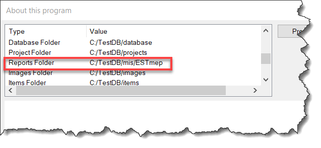
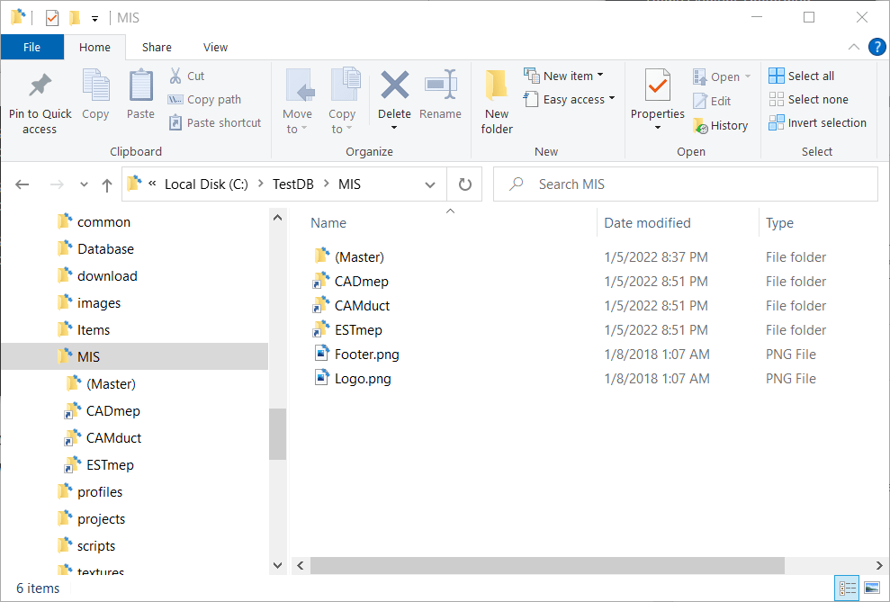
Step 1: Find Where Your Reports Are Located
Using CAMduct or ESTmep you can pick Help -> About or type AppInfo at the command line in CADmep. You can then scroll through the window to see where the Reports are located. Alternatively, you could use the Edit Configuration utility to find this folder as well.
Note that this screencap was done in ESTmep so you see the ESTmep subfolder. The mis folder is actually the root where all your reports are.
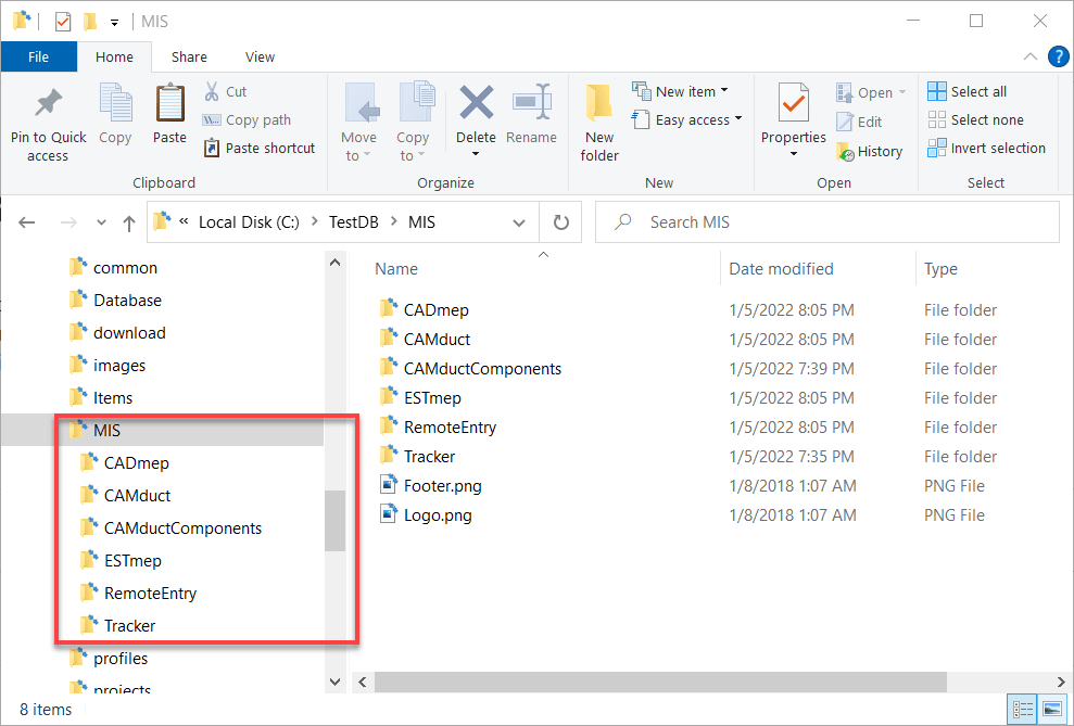
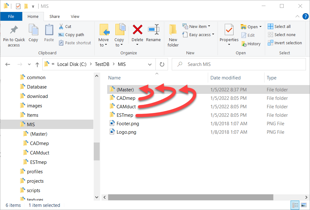
Step 2: Copy All Report Folders to a New Folder
The next step is to copy all the reports from the various product specific folders to a new master folder location to store the reports. In this case, we’ll call it (Master) just to make it super obvious. Notice we also deleted the folders for CAMductComponents, Tracker and RemoteEntry because I’m not using them. You can choose to include them if you need them,
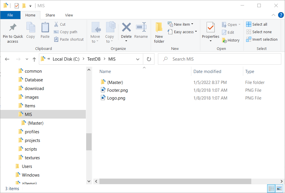
Step 3: Backup and Delete the Original Reports Folders
When you’re done, you should back a backup of the product specific reports folders elsewhere incase you want to go back to the original config. Once backed up, you need to delete the original product specific reports folders. When you’re done, your reports folders will look like this…
Step 4: Create Junction Links for the Product Folders
Here’s where we do the magic. Windows allows you to create what’s called a Junction to other folders. A Junction is just another virtual folder that looks at the contents of another. Junctions are how Windows has a “My Documents” folder that really points to “C:\Users\<Username>\Documents“.
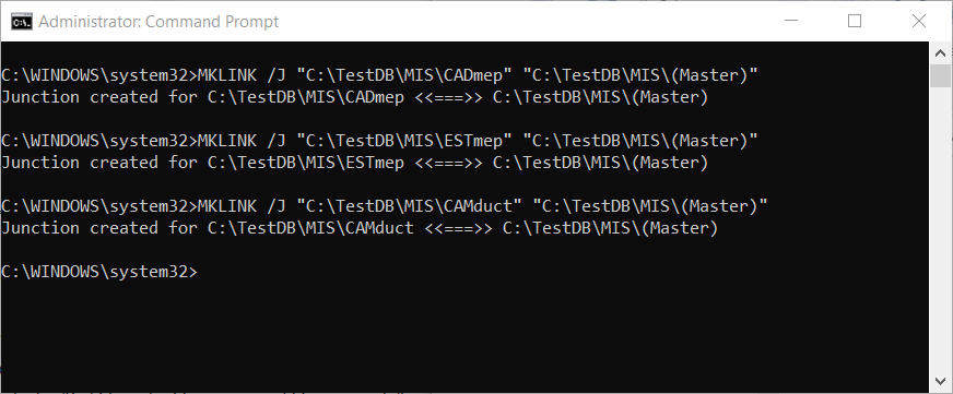
To create a Junction you need to open a Command Prompt with Administrative permissions. One that’s done, you use the MKLINK command to make a Junction Link to a Junction Target. The syntax looks something like this….
MKLINK /J "link folder" "target folder"
Here’s a screencap of my DOS Command Window where I make Junction Links to the (Master) reports folder…
When done (if Successful) you’ll see those product specific folders again for CADmep, ESTmep and CAMduct. But this time, you’ll notice the icons are slightly different and look like a shortcut icon even though the folder acts like a regular folder.
Here you can see a side by side recording of the process happening in real time…
Step 5: Use Fabrication As Normal
Once you have the junctions created, you can use your products as normal. Each fabrication product looks to the folder specific to it, which Windows redirects to the file in the (Master) folder.
One thing to note, is that when browsing the (Master) and product specific folders, the only clue that these are Junction Links is the Shortcut looking arrow on the icon. If you don’t know what’s going on, it would appear that you have 4 folders each with the same files. But if you try to delete the files in one, they will indeed disappear from the other folders too. After all, these folders are Links back to the Target.
Here’s a recording of all 4 folders show at the same time. You’ll see that changes to any one also happen to the others. You may need to Refresh the views to see the changes but they indeed are seen from the Target and all Junction Links. This means that while there’s 4 folders showing the same files, they only take up the size on disk in one folder.
Summary
Junction Links work well for letting all (or some) of your Fabrication products use the same list of Reports. But there are a few noteworthy items to be aware of….
Junctions Links and Point to Targets on a different DRIVE or FOLDER as long as it’s on the SAME machine. You can’t make a link to a target from a computer to a server for example.
If you access your database from a network location, you need to make make the links from the server so your IT Department may need to get involved. Your local software when accessing the server share will honor the junctions it sees on the server.
If you don’t know what’s going on or look closely, it appears you have duplicate data. Make sure you don’t delete things from one folder thinking they’ll still be in the others.
If you want to undo this setup, you should delete the Junction Links FIRST just like any other folder before deleting the Target folder. If you delete the Target first, the you’ll have trouble deleting the links.
IF you Sync your database from a master source location like Dropbox or using a utility like Robocopy, the Junctions are NOT copied, but are instead copied like regular folders. There may be some special utilities that copy the junctions but I’ve not found them. So what is 4 views of 1 copy of a file on a network, when synced to your local system becomes 4 copies of the files in 4 folders. For the most part, it’s not an issue as you manage from the master source location. None the less, this nuance is worth mentioning. Most Sync utilities do NOT recognize the special nature of a junction and treat them just like a folder.
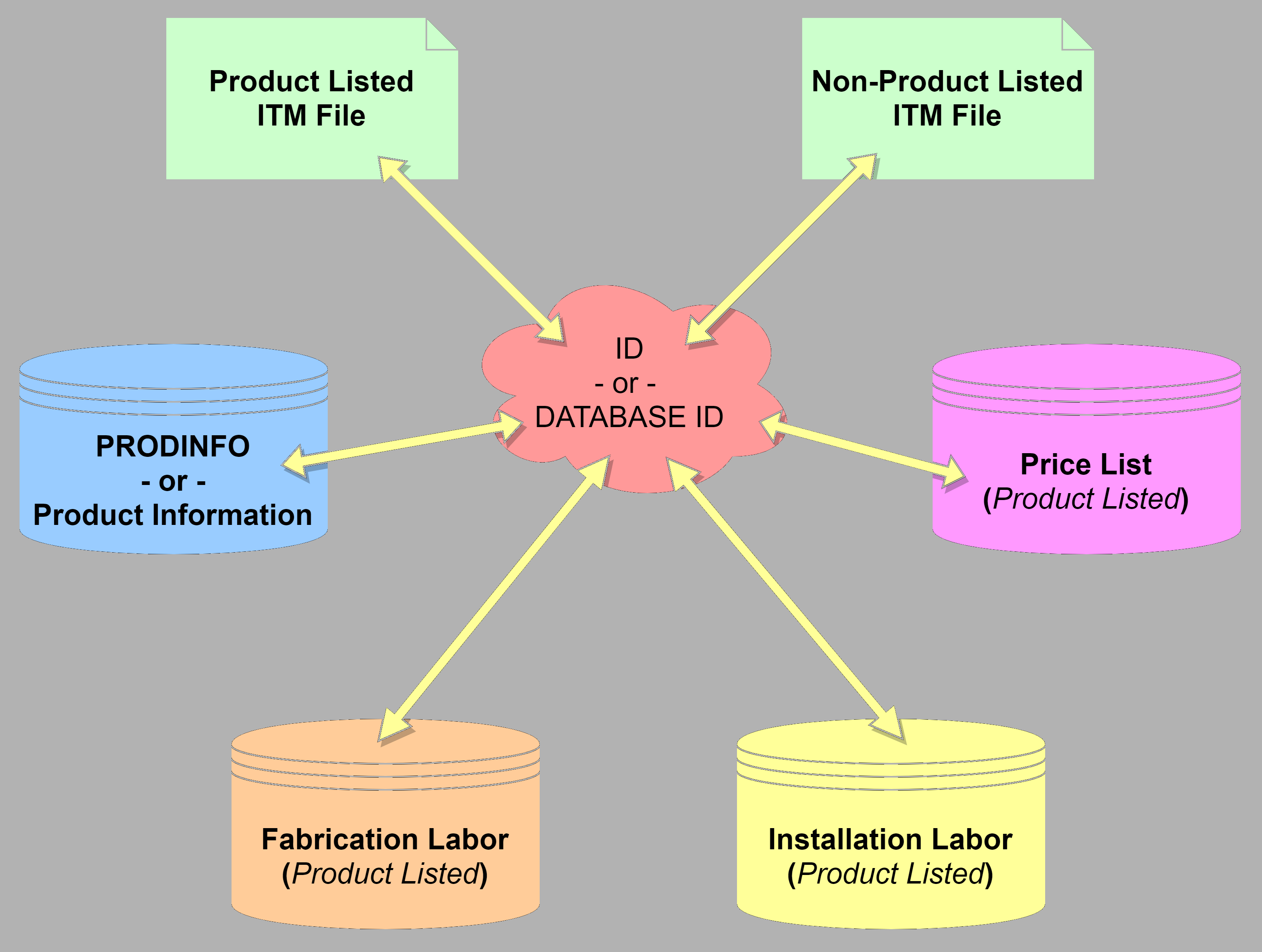
I have a lot of people ask how Pricing, Laborand Product Information (ProdInfo) works in Autodesk Fabrication. It’s a simple concept once you understand it. But it’s also rarely illustrated graphically so I’ll attempt a more graphical explanation here.
At it’s core Product Information requires the use of an ID, sometimes referred to as a Database ID. Pricing and Labor can be handled two separate ways depending how you need to price and labor your items. One of those ways is using Product ListedPricing and/or Labor. When using Product Listed Prices or Labor, you also use an ID.
Generally speaking, 100% of your parts should have and ID. ID’s should also be unique without a very good reason for duplication. There are a couple good reasons to duplicate ID’s across content but we won’t get into that here. If this article is helpful to you, those reasons would only serve to complicate the issue at this point.
Product Information & Product Listed Prices & Labor
When you have an IDassociated with your ITM content, that ID serves as the “Glue” to tie together all the other database tables in Autodesk Fabrication. An ITM with an ID, looks up that ID in the Product Informationdatabase to find the related product information. IT also does the same for Pricing, Fabrication Labor and Installation Labor.
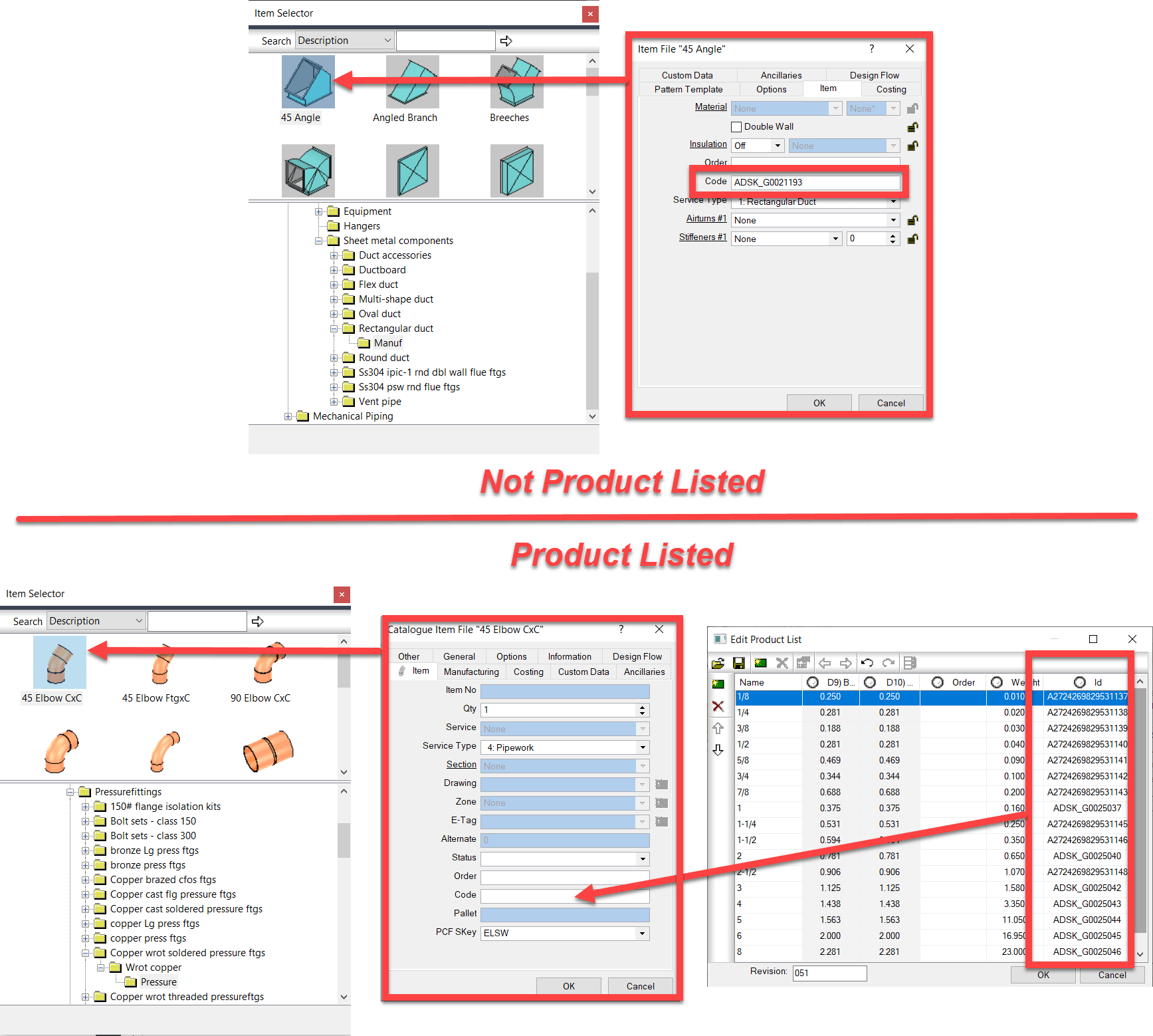
The following images shows where the ID is stored in your ITM Content. For ITM’s which are NOT Product Listed, you simply type the ID into the “Code” field from the Properties window.
For Product Listed ITM’s, it’s handled slightly different. You add the ID column to the Product List and add the ID’s there. When you add a product listed ITM to your model or takeoff, the value of the ID for the size you select gets automatically placed in the “Code” property. When that ITM is merely sitting in your library on disk, the value here doesn’t matter. It can be blank or any one of the ones in the Product List. Adding the ITM to your model then updates it to the proper ID.
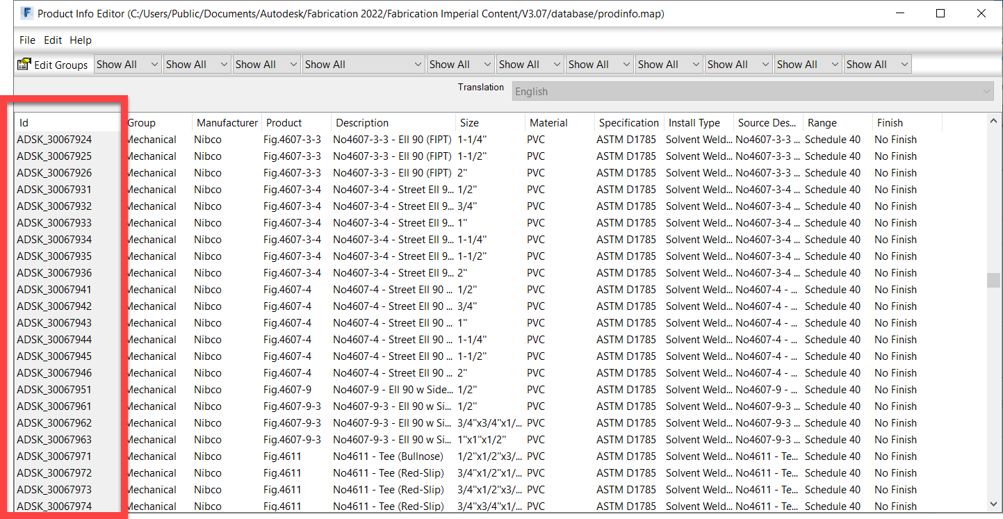
Product Information
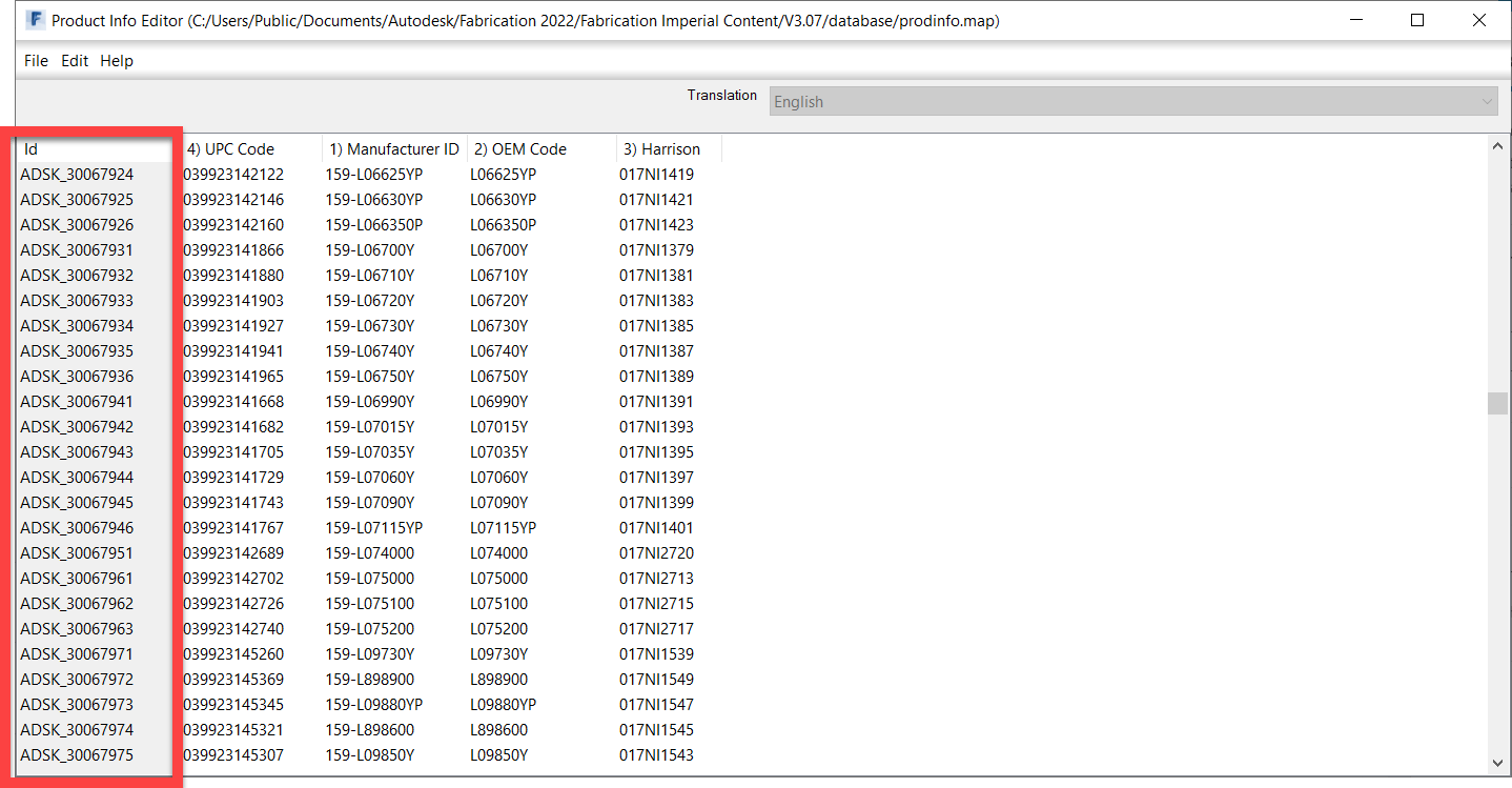
Product Information or ProdInfo for short lists additional data about the fitting or item. The following image shows the related data in ProdInfo with the ID column outlined.
In addition to standard product information, you can also change to a Supplier view of ProdInfo where you can add additional columns for any other types of data or numbers you want to track. The following image shows some added data fields like UPC Code and Harrison HPH codes.
Pricing
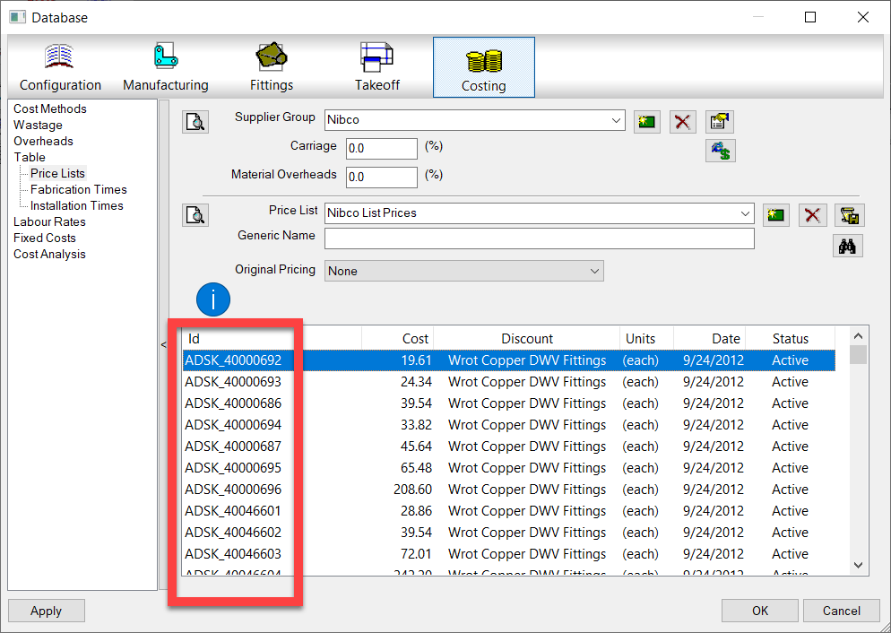
The following image shows a Product ListedPricing Table. The ID is outlined. Here’s where you can add pricing information to the ID of the ITM. Note, the term Product Listed Price here is a little confusing because “Product Listed” prices can apply to non-product listed ITM’s. While an ITM may not contain a “Product List“, the pricing table is still a “List of Products” that are referenced by ID.
Labor (Fabrication & Installation)
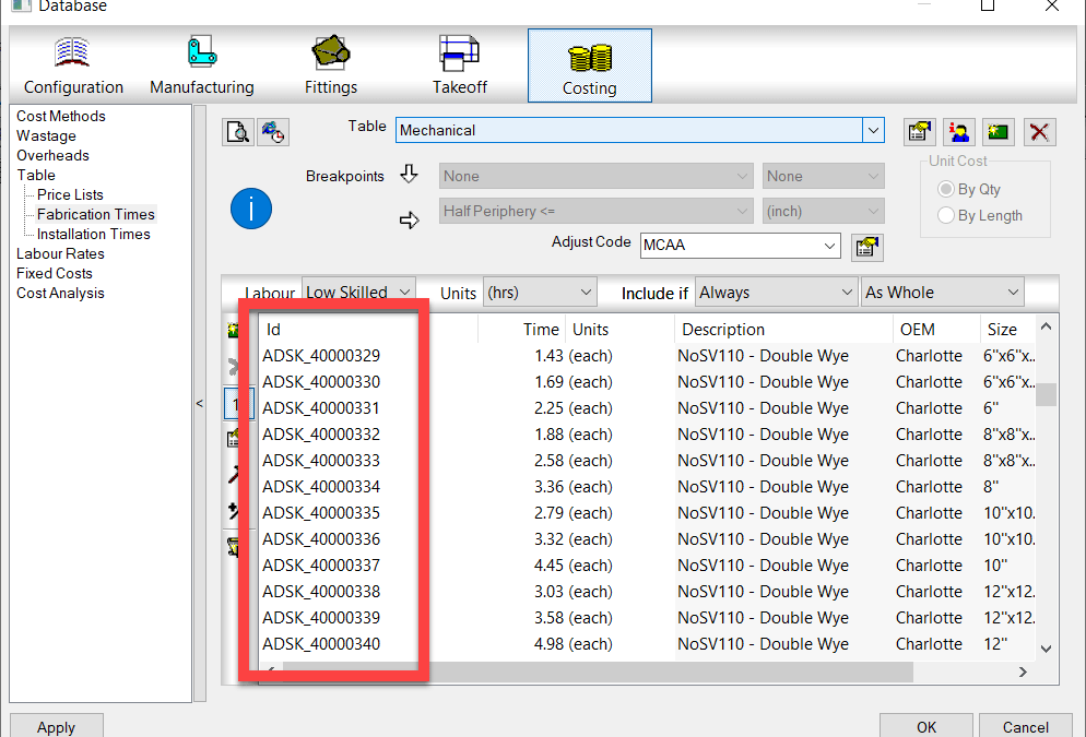
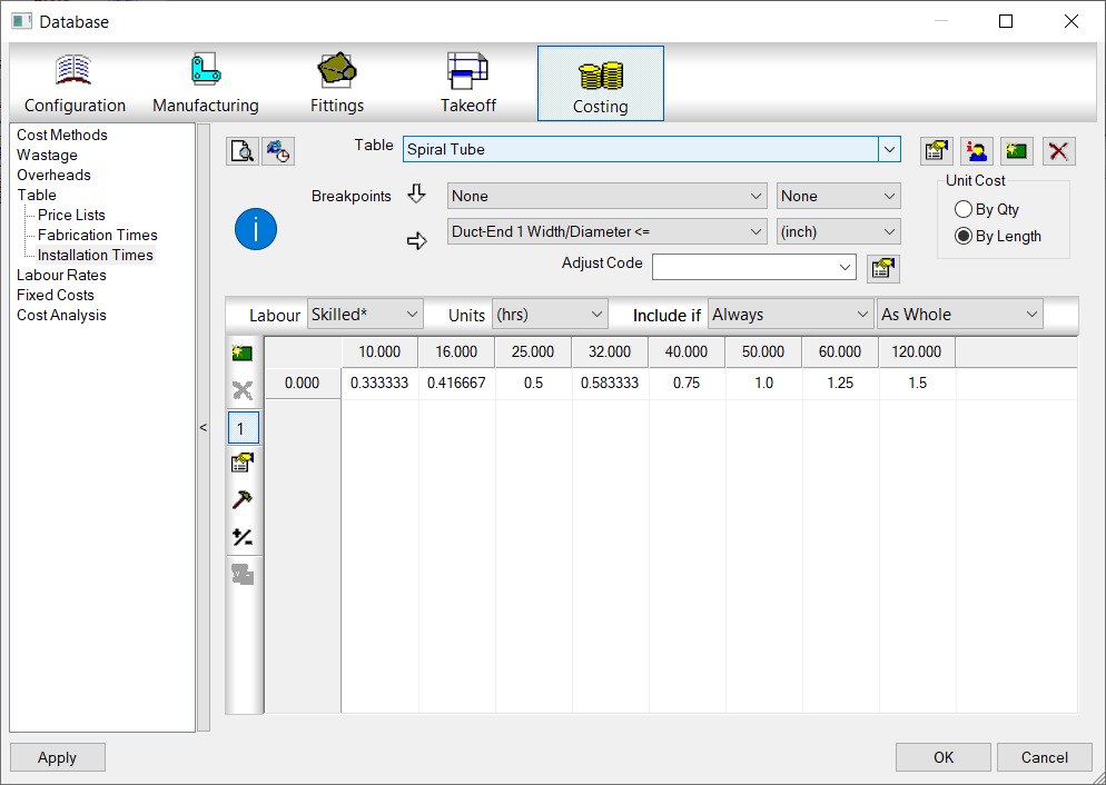
In the same way Price List’s work, Fabrication and Installation Labor work in a similar way. Product Listed labor can apply to any ITM, Product Listed or not as long as it has an ID. The following image shows Fabrication labor but Installation Labor works identically.
Breakpoint Pricing & Labor
A second way to specify Price and Labor doesn’t require ID’s because they’re not looked up from a list. These would be Breakpoint Price and Labor tables. With this type of Price or Labor table, you build a 1d or 2d Breakpoint Table that uses the part’s size as a guide to look up the proper price or labor rate in a matrix.
Price Breakpoint
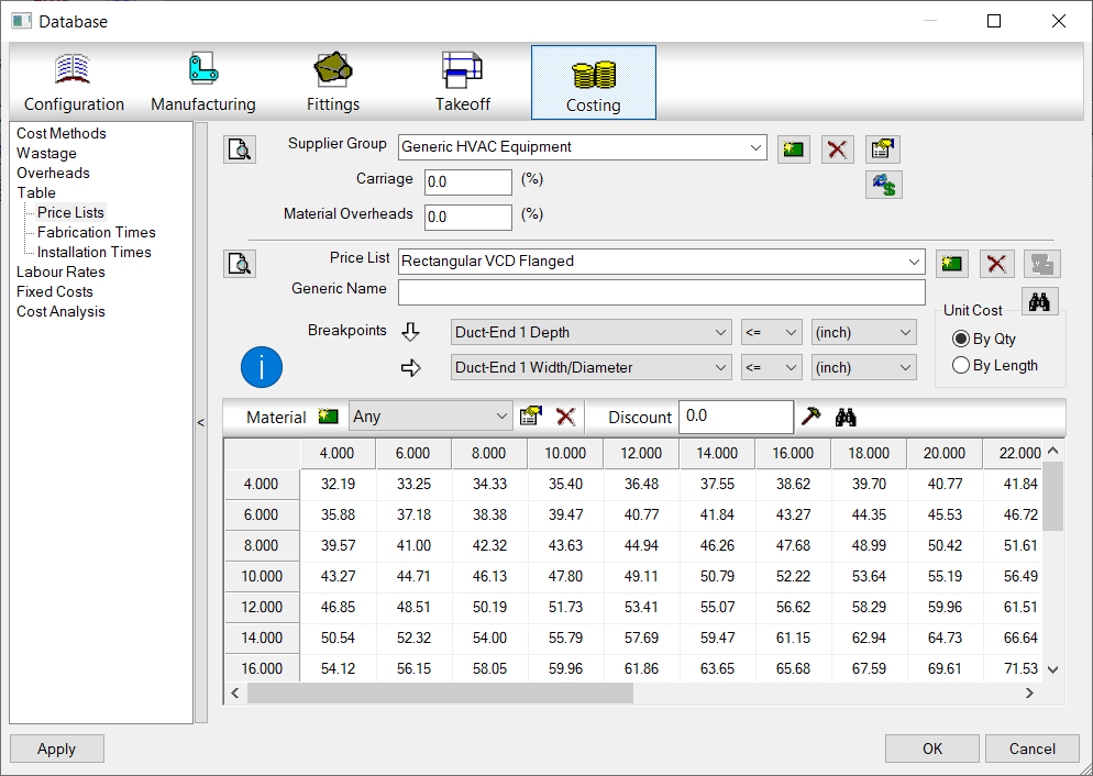
The following image shows a Pricing Breakpoint table. You can make more than one breakpoint grid and have each apply to a different material if you have the need.
Labor (Fabrication & Installation) Breakpoint
Similar to a Price Breakpoint, you can make a matrix for Labor as well. With LaborBreakpoints, you can also make more than one matrix and have it apply to various properties of the item labor is being applied to like Insulated or Non-Insulated.
Finding the Right Price & Labor Tables
While all you need for ProdInfo is an ID on an ITM and matching ID entry in the ProdInfo Database, Price and Labor need an extra step.
Price and Labor can have multiple tables to help you organize the values or even manage the price for the same item from multiple suppliers. To handle this, you set the tables in the ITM properties. This is true for both Product Listed ITM’s as well as Non-Product Listed ITM’s.
Setting these tables tells Fabrication which table to look in to find either the ID or the Breakpoint table which uses size and property criteria to apply to the ITM.
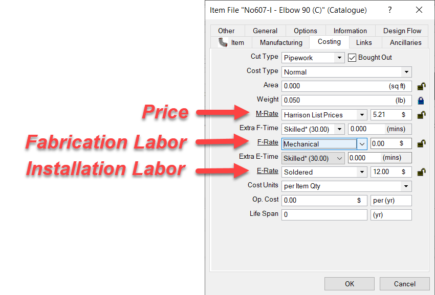
The following image shows where those tables are configured in the Costing tab of the ITM properties.
M-Rate is were the Price of the material comes from. This is set typically for bought items where you pay a set price. If you leave this set to “None“, material pricing would be calculated on a “Price per Pound” formula based on the material weight. This is typically done for Fabricated Sheetmetal fittings where the weight of the Sheetmetal is calculated based on area and gauge and then priced per pound. For piping or bought items, this table would typically point to a table that contains the pricing.
F-Rate is where you select the Fabrication Table to use to look up the Breakpoint Table or ID if Product listed labor. This is most commonly set to “None” for Piping items or other bought items where you just buy them but don’t fabricate them. It’s usually set to a specific table for Sheetmetal fittings which you fabricate and want to calculate fabrication labor.
E-Rate – This table is for Installation Labor. The “E” in “E-Rate” stands for “Erection” if that helps you remember. This will be set for most contractors who are installing duct or piping. It would typically be set to “None” if you were a fabricator only selling to others who install.
Summary
Hopefully this helps give you an idea how pricing, labor and product information functions (at a high level) in Autodesk Fabrication. There’s a lot more strategy and nuance you can get into but this is a good place to start understanding the basics of how it all works.
Are you familiar with Windows Quick Assist? Windows already had Remote Assistance which can typically require special permissions or setup to work. Windows Quick Assist is more like TeamViewer or GoToAssist and very ease to use.
Quick Assist is a Windows 10 feature that lets you give assistance to other users or receive assistance from other users. No special permissions or setup required other than the person giving assistance needs a Windows account. The person receiving assistance is not required to authenticate.
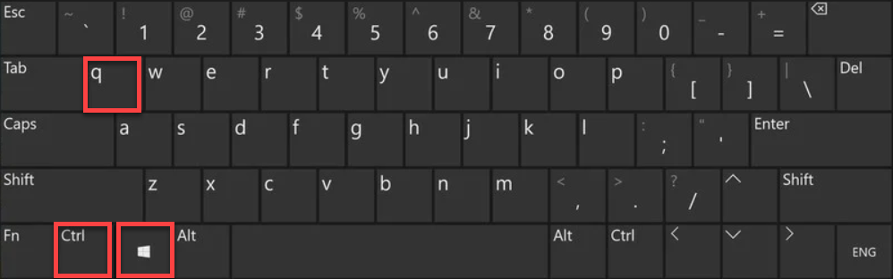
To start Quick Assistance press the CTRL+WINDOWS+Q keys on your keyboard.
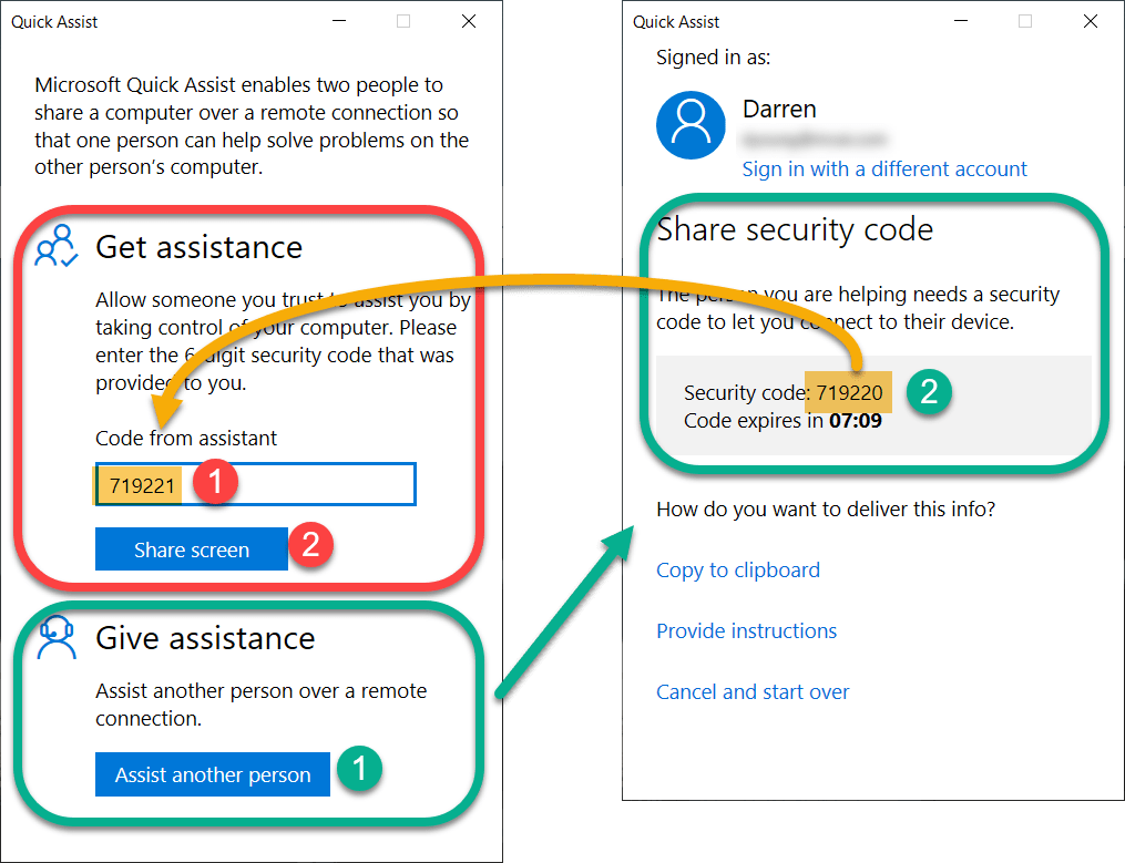
From here, a dialog is displayed giving you a choice to GET or to GIVE assistance.
If you intend to GIVE assistance, you’ll be given another window with a code to give to the person you want to help.
If you’re going to GET assistance, enter the code given to you and share your screen.
That’s pretty much it. The rest if pretty self explanatory.
If you’d like more details into how Quick Assist works, check out this post on Microsoft’s web page…
Seems obvious once you see it but sometimes the easy things are the most ellusive.
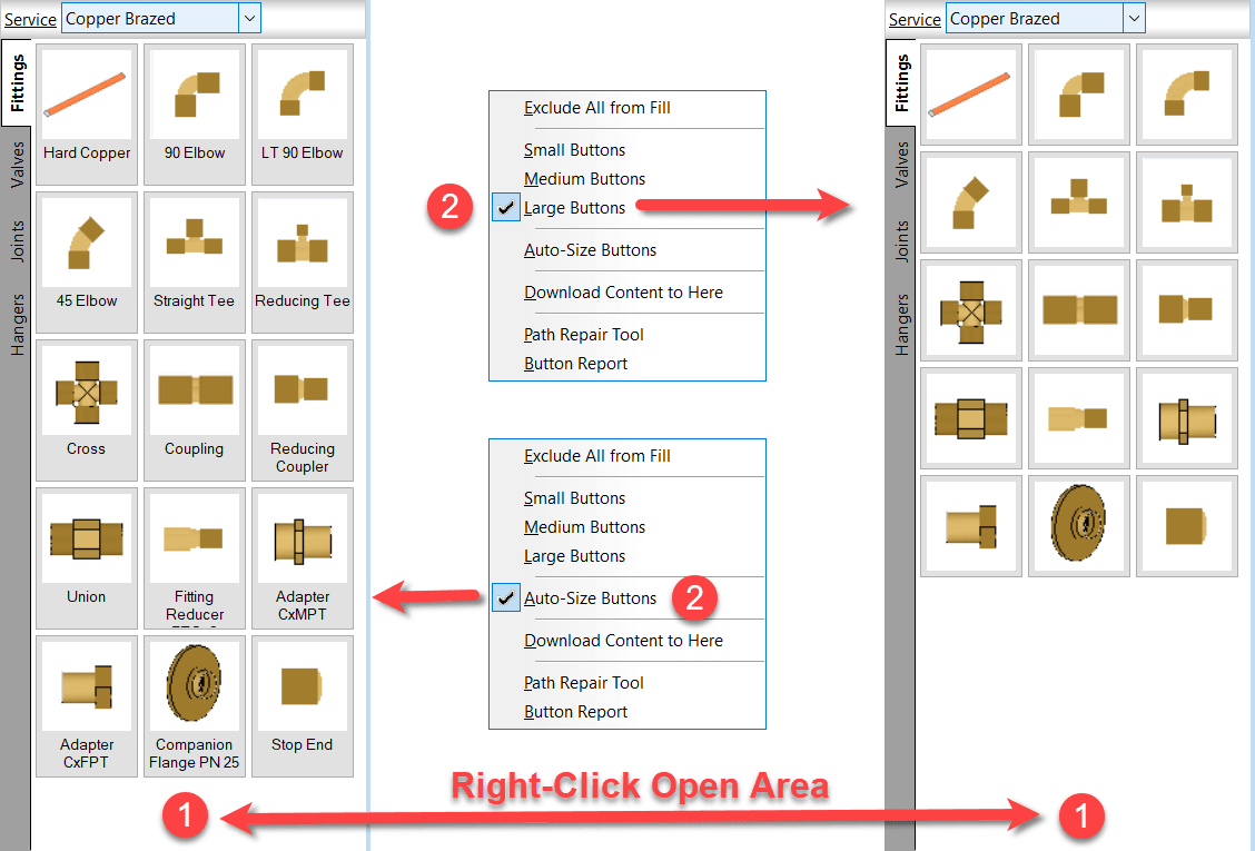
If you’re noticed descriptions on some of your computer’s fabrication palettes and not others, it’s likely the “AutoSize” option you’re looking for.
Right-Click on an open area of the service palette and select the option you prefer. This applies to CADmep, CAMduct and ESTmep. Revit…not so much. Revit likes to do it’s own thing.