In a recent LinkedIn post, the topic of Tolerance Stacking was brought up. I’m not a machine designer, but I’ve spent a lot of my past life in Manufacturing. In that world, the term was used frequently. If the term was used in Construction, it certainly wasn’t when I was listening.
Tolerance Stacking can be described (in my mind) as the accumulation of allowable tolerances to a point where the design is no longer suitable for it’s intended purpose. Errors resulting from Tolerance Stacking are caused by a few things…
- Lack of tolerance awareness
- Poor annotation and documentation of tolerances
- Both of the above
Tolerance Stacking Explained
The best way to understand Tolerance Stacking is from a few examples. In our first example, we see a part 10 Units long with 9 holes, equally spaced 1 Unit apart. Take note of the RED dimension on the right.
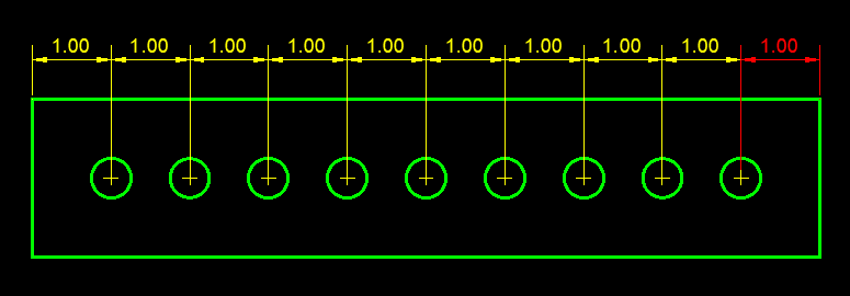
You may have seen parts dimensioned like this. Looks pretty normal. Now lets consider this same part and assume the dimensions have a tolerance of +/- 0.0625 (1/16 Inch). Now lets also assume that all the dimensions are in the negative -0.0625. The following graphic illustrates this condition. Again, notice the RED dimension on the right.
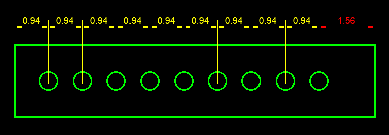
Is the overall length really have enough tolerance to compensate for the accumulation of those tolerances?
Now lets look at the same part, same tolerances but annotated/documented differently. It’s not as “pretty” and takes up a lot more real estate on your drawing.
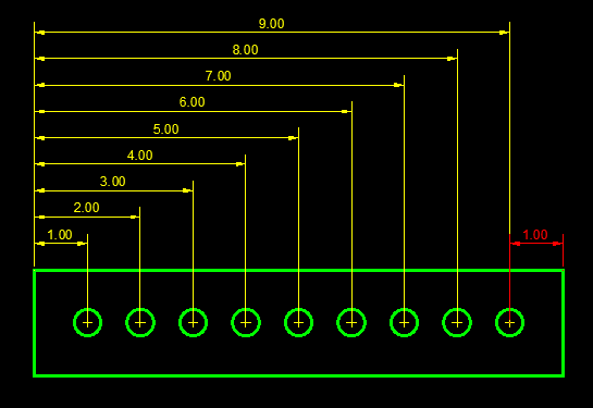
But lets look at that same -0.0625 extreme case tolerance in this scenario. Once again, keep an eye on that RED dimension to the right.
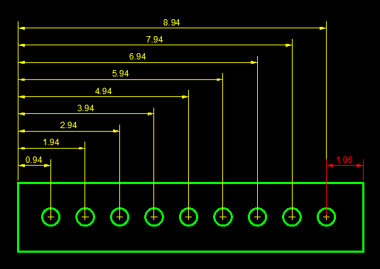
This latest example solves the Tolerance Stacking issue by clearly outlining where the tolerances are allowed. In fact, in construction, we’re already doing this. We just don’t call it Tolerance Stacking.
In construction, one of the ways we eliminate Tolerance Stacking is by dimensioning to gridlines and columns. Dimensions in relation to known fixed points minimized Tolerance Stacking.
Are you old enough to remember when rafters were layed out by hand on the job site and cut individually? You would cut one and use it as a template and use that to mark the others. You never installed the template and used the next cut as your template for another. This minimized Tolerance Stacking as well.
Geometric Dimensioning and Tolerancing – GDT
What’s less familiar, is another concept used heavily in automotive and other precision manufacturing. It’s called Geometric Dimensioning & Tolerancing or “GDT” for short.
Traditional linear tolerances have flaws. GDT on the other hand more accurately describes “features” and allowable deviation from the desired location using a more complex form of graphics and symbols.
Once again, the best way to explain this is with some illustrations. The following example shows a square part with a hole in the middle. Pay close attention to the RED dimensions.
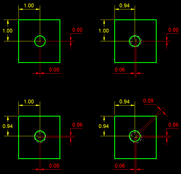
Top Right – Hole moved 0.0625 to the right
Btm Left – Hole moved 0.0625 up
Btm Right – Hole moved 0.0625 in both directions
In this example, you see when the hole is moved to the maximum tolerance in both directions, it’s actually further away from it’s desired position than 0.0625.
This is where GDT comes in. In this last example, GDT is used to “Describe” the allowable deviation from it’s ideal position.
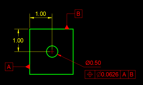
There’s actually an ASME Standard for GDT (Y14.5.2) and a full explination of GDT is not only beyond the scope of this blog but my knowledge, There’s a lot of courses out there specifically for this but a good “101” description can be found here.
Given trends in Prefab, Modularization, and Construction becoming more like Manufacturing….Makes you wonder….should there be a “GDT” style of documentation for construction?