Autodesk Fabrication: Best Practice #4

Make sure ALL of your ITM content has a Database ID assigned to it.

A database ID is a unique identifier for content. There should be a single Database ID for any ITM that is NOT Product Listed. For Product Listed ITM’s, there should be Database ID for each entry in the product list.

For ITM’s that are not product listed (typically fabricated sheet metal fittings or other content where the ITM only represents one size, you can put the Database ID in the “Code” field of the ITM Properties as shown in the following image…

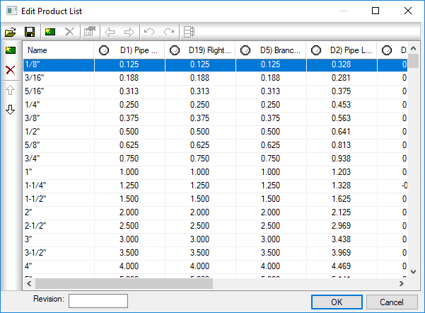
For ITM’s that are Product Listed, the Database ID should be in the ID column of the Product List. When you place an instance of a product listed ITM in your model, you select a size from the product list, When you select that size, the Database ID associated with that size it automatically entered into the Code field of the ITM Properties like shown earlier, The following image shows the Database ID column in a Product List…


Why Use A Database ID?

The Database ID is a useful component to managing an Autodesk Fabrication configuration. This Database ID can be referenced by other aspects of Autodesk Fabrication should you choose to use them. The Database ID is what can link your content to….

  • Price lists
  • Fabrication Labor
  • Installation Labor
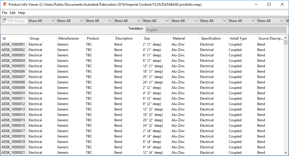
  • Product Information (ProdInfo)

Even if you don’t use ESTmep for estimating  and don’t want to use the Price and/or Labor features of the database, Product Information is tied to the Database ID and is used to store additional meta data about your content like Manufacturer, Size, Description, etc. Even if you’re not using ProdInfo now, it’s still a good idea to use Database ID’s because adding them to the content is the most time consuming part. It’s easy to add them when building content, more cumbersome later after the fact. If all your content had Database ID’s assigned, it’s much easier to implement ProdInfo, Price and/or Labor later down the road.

The following Video shows how to access the Database ID of Product Listed and Non-Product Listed ITM’s. It also shows you 2 different sizes of a product listed ITM in a drawing and how Autodesk Fabrication automatically assigned the Database ID from the Product List for the corresponding size into the Code field of the ITM Properties.


Key Database ID Takeaways

Here’s a few pointers when working with Database ID’s:

  • Each Database ID should be unique and not assigned to other content or sizes.
  • Managing Database ID’s using a spreadsheet or other database makes managing them much easier.
  • Your database ID can be anything you want but should have some sort of naming standard associated with it.
  • Your Database ID Naming standard can be as simple as a prefix followed by incremental numbers to something complex with special codes and formatting to indicate other aspects of your content. (e.g. Valves, Pipe, Sheetmetal, etc)
  • You can use Autodesk or other Vendors ID’s if they already have them assigned and use your for anything you create or replace them all with your own company Database ID’s if you are particular about naming standards,
  • Don’t reuse ID’s if the content that once used them is now obsolete. Legacy/Archive drawings still reference these numbers. Simply flag them as being obsolete in the Spreadsheet you are managing them with.

Beware: Autodesk Subscriptions, Industry Collections and Trust

Everything Must Change

It’s no secret that Autodesk is moving to an annual subscription model. There’s a number of reasons Autodesk tells you it’s for the flexibility and benefit of the customers. Some of these benefits include…

  • Predictable annual licensing costs
  • Lower initial cost for procurement (no more large initial upfront cost)
  • Flexible licensing model (add/drop licenses as your business needs)
  • Ability to release product updates anytime

All these benefits are true, legitimate reasons a customer would want to move to a subscription model. If you look at the current pricing promotions, converting existing licenses to the Industry Collections looks very financially attractive.

A number of years go, Adobe rolled out subscription licensing. Revenue suffered for a couple years and then rebounded. Customers were no longer making large upfront purchases but as time went by and subscriptions increased, revenue rebounded and higher profits ensued. And because revenue wasn’t tied to an annual “release” cycle of software updates, it’s a more predictable and stable revenue stream. It’s no wonder Autodesk is following in Adobe’s footprints. As a business, they’d be foolish not to and even as a customer, I don’t begrudge them to make a profit and give them more flexibility in running their company.


The Problem

When Adobe made the transition, revenue was significantly impacted and returned in a couple years. Autodesk is seeing the same thing with one key difference. Autodesk has underwent 11 straight quarters of losses. Adobe never lost money. Clearly, Autodesk’s customer base isn’t as understanding and you see a lot of public facing criticism in public forums against being forced into this model.

Part of the problem is the longevity of the data Autodesk customers produce compared to Adobe. Autodesk customers often maintain engineering or product documentation for decades. That pretty marketing graphic made from Adobe products likely isn’t managing product or building data 2 decades later.

The other part is Autodesk’s horrible track record with pricing. Autodesk isn’t a software company, they’re a sales organization and they’re very good at it. They have a history of squeezing the re-seller channel, taking over their major accounts and competing with their third party partners.

Here’s a few examples…

  • Autodesk tells their re-seller channel they’ll partner with them on major accounts. The fact is many find themselves frozen out of the discussions, especially if there’s any hint of looking out for the customer’s interest.
  • It was very common to be able to “upgrade” your annual maintenance contracts to higher end software. To go from AutoCAD to AutoCAD Mechanical or AutoCAD MEP or was cheaper or only slightly higher than staying on AutoCAD. When your maintenance contract was up for renewal a year later, you then see the deferred price increase you just were hit with. If you wanted to “downgrade”, you paid a fee, typically the cost difference between the two products.
  • When Autodesk stopped selling the Revit MEP Suite, they rolled out the Building Design Suite. If you were already on the Revit MEP Suite, you were grandfathered in could maintain your contract. It was during this time the sales channel was running a “promotion” to upgrade and telling customers they should act fast before they were enforced to upgrade at a higher price. The problem, a) The Design Suite promotions ran almost continually to show vertical product sales increases to Wall Street and b) They would “uplift” customers to the Design Suites for free a mere 6 months later. One company I worked with, Autodesk tried to sell over $300k in upgrades this way only to get them for free months later. They claim they didn’t know but how could they not? I’m just a dumb customer, I knew…because it’s happened before.
  • Autodesk had their sales staff and resellers promoting selling Perpetual licenses “while you can still get them”…and customers did. All the while I suspect they knew they’d just increase the maintenance subscriptions to more than the annual subscriptions. Your “savings” in cheaper annual renewals just was wiped out.

If you look at the various changes has made over the last 2 decades, rolling out maintenance subscriptions and finally making them mandatory to replace upgrade charges or rolling their new annual subscription model, you’ll notice a common theme. All of these changes create an “Artificial Crisis” for customers which results in collecting as much as they can while delivering as little as possible,  Given their track record of deceptive and misleading sales, it’s no wonder customers have a lack on trust and are resisting these changes.


What Should You Do

Customers like to think they have control. Autodesk likes them to think that as well. But the fact is, you don’t. I hear a lot of talk from customers about maintaining their existing perpetual licenses and resisting the move to subscription, Personally, I think that’s misplaced.

Autodesk wants you on subscription and that’s where you’ll go, sooner or later. You don’t have a choice without switching software, Want to Upgrade, Downgrade, Cross-grade to another product, move from Standalone to Network Licensing, you’ll have to go on subscription. Unless you don’t want to pay more annually to maintain your perpetual licenses than it would to go to subscription, you’ll move…sooner or later.

Willing to stick it out? Feel free but in industries like construction that are really evolving with new technology workflows and require all team members to be on the same page to leverage collaborative project workflows it’ll be tough to do. Even with the evolution of technology to the cloud and big data analytics, other industries are going to be hard pressed to not upgrade. How many people do you know running AutoCAD r14 or even 2008 for that matter?

Still not convinced and plan on hanging onto your perpetual licenses forever? Good luck. That “Navisworks Manage” you have you’re free to run forever as long as you can find the hardware that will run it. In fact, you can’t even buy a maintenance subscription anymore because we at Autodesk stopped making it. You’re welcome to buy a subscription to our new “Navis Quantum” anytime however,

If you’re really dead set on maximizing that initial investment you paid for your perpetual licenses, you really have only one option…stop paining maintenance subscription now. Ride it out a couple years and buy subscriptions when you need them. They’ll be running a promotion sooner or later. With a fiscal year end of January, the new years is always a good time to negotiate pricing.


What’s the Future Hold?

So let’s just assume you’re on annual subscriptions down the road. What can you expect next?

Because you can add/drop licenses easily with annual subscriptions, they’re easy to scale with your business. When business is good, so is Autodesk. But what if there’s another recession and people start dropping licenses?

While most resellers and Autodesk are promoting Industry Collections, there’s a little know catch that every contact I asked either in the reseller channel or at Autodesk didn’t know (and I asked many). The Industry Collections limit you to running 2 concurrent products for the same user on the same computer. If you’re in the Mechanical Electrical and Plumbing construction industry, it’s common to run AutoCAD, with CADmep (runs in AutoCAD) and Navisworks at the same time…maybe ever Revit too.

You literally can’t find information on the FAQ’s regarding this restriction and the sales people are telling you that you can drop your Navis and CADmep licenses and migrate your Revit/Acad to an AEC Collection and save money and licenses without disclosing this restriction.

The only place you find information is on the Knowledgebase (if you search for “concurrent usage”)…

https://knowledge.autodesk.com/search-result/caas/sfdcarticles/sfdcarticles/Industry-Collections-Licensing.html

Or in a single Discussion group post by Autodesk…

https://forums.autodesk.com/t5/installation-licensing/industry-collection-licensing-basic-information-amp-licensing/td-p/7250896

It’s not found in the other countless pages and links your most often referred to. Reading closely, you’ll notice, one talks about the restriction generically and the other only pertaining to network versions. Autodesk re-sellers don’t have access to Collection licenses (only individual products) and can’t even test. So hows this work and how does it apply?

Upon much research by myself, my industry colleagues and Autodesk, come to find out it’s not a “technical” limitation rather a “policy” that’s not enforced with technology. So, what happens if/when…

  • They start enforcing the policy?
  • They perform your next license audit and see you use more products that you should concurrently?
  • The economy slows and their revenue drops so they implement a “no concurrent usage” policy?

As you can see, Autodesk is in complete control and your only option once on subscription is to pay or or stop using the software. There is no longer a perpetual license to fall back on.

Ok, fine, you can just buy an extra Navis or Revit subscription. But those need to be assigned to a specific user who also has access via the Collection. Or if you’re preference is network licensing, forget it. Revit and Navis are no longer able to be purchased with network licensing unless on a subscription.

If you don’t think it’ll happen, think again. For the second time in just a few short months, Collaboration for Revit isn’t enforcing licensing. The first time this happened, when they turned it on many users were left without access to their projects and unable to work. They should have had licenses, true but C4R configuration and setup is not straight forward. It’s common to grant access to people in a project. They may not realize you also need a license provisioned in another system. In fact, it’s very easy to have multiple licenses assigned to the same user from different companies essentially giving Autodesk double revenue and you’ll never know.

Given their misleading tactics in the past, how do you know this disabling of license checking isn’t intentional in an effort to get people to start using and depending on the software only to force a purchase down the road? It’s well known that AutoCAD was as popular as it was due to the easy of piracy back in it’s infancy.

So in summary, there’s really only a few practical options,..

  1. Give in and move to subscription, you’ll be there anyway eventually.
  2. Drop your maintenance subscription now if you can and ride it out a few years
  3. Move to another product/vendor.
  4. Maintain your perpetual contracts and pay more than any other option,


CAMduct, OPUS Parts, Edited Developments and Proxies

Two Problems….One Solution

In CAMduct using OPUS parts and/or ITM’s with developments that have had edits made to them can on occasion cause some headaches. The following process can be used to resolve 2 different issues in CAMduct, Those are….

  1. Retain edited pattern developments
  2. Eliminate proxy database entries with {curly brackets}

1) Retaining Edited Developments

It’s fairly common for CAMduct users to edit pattern developments. Occasionally, they may want to save these edited developments for later use. A good example is using a number of separate ITM’s for damper blades. Each ITM is a different size with perhaps some edits to the pattern for slots/holes for U-Bolts, notching to clear screws, etc.  A CAMduct user can use any CID Pattern for the basis of their edits. For example, they could use an Elbow CID, delete all the developments belonging to the elbow and redraw something completely from scratch. The problem with this is that if you ever try to change materials or edit the ITM in any other way, the development edits are lost and the original development is back minus your changes.

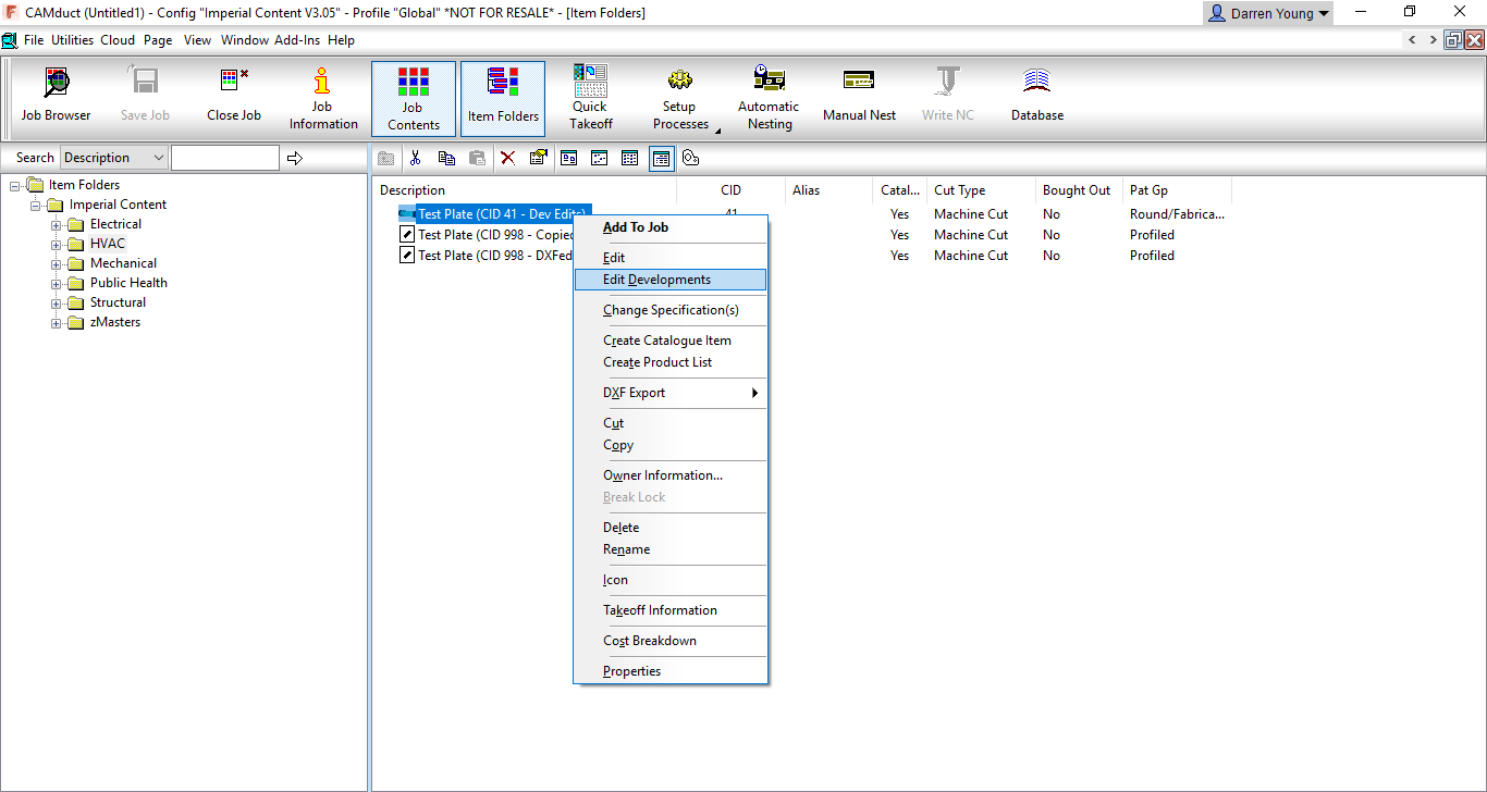
In the following image, you can see that Right-Clicking on an ITM made from CID 41 offers a couple editing options In this case, we’re going to select the Edit Developments option.
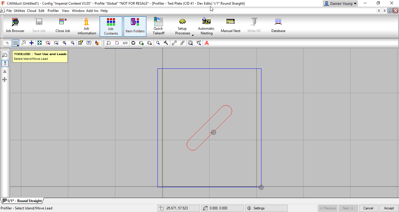
When you select the Edit Developments option, you’re brought to the OPUS Part editor shown in the next image. Here you’ll see that there’s been a 45 degree slot added to the development.
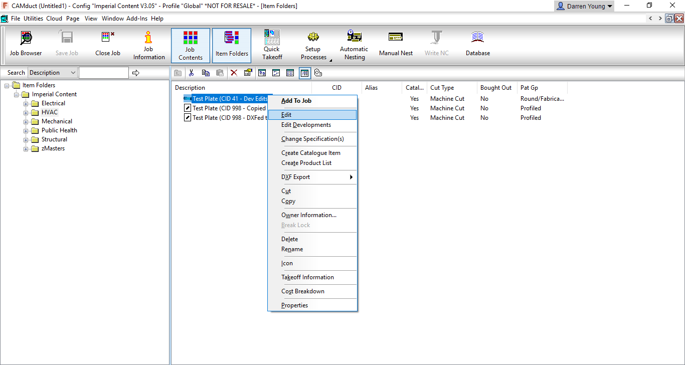
On the other hand, you can also Right-Click on the ITM and select EDIT from the menu as shown in the next image.
This option brings up the standard ITM editor which you should be fairly familiar with. The part you see in the ITM editor may not look anything like the development, it may look very similar or in fact be the same part developed if there were no edits made. From the ITM Editor, click the “Develop” button in the lower right and you’ll again be brought to a dialog that displays the part(s) developments. This time you’ll notice that the 45 degree slot is not shown. In fact, it’s displaying the unedited development for the CID you’ve selected based on the Dimensions, Options, etc. as entered in the ITM Editor. From the ITM editor, the dimensions, options and other settings drive the size/shape of the developments. It wouldn’t know what to do with your edits so it gets rid of them,
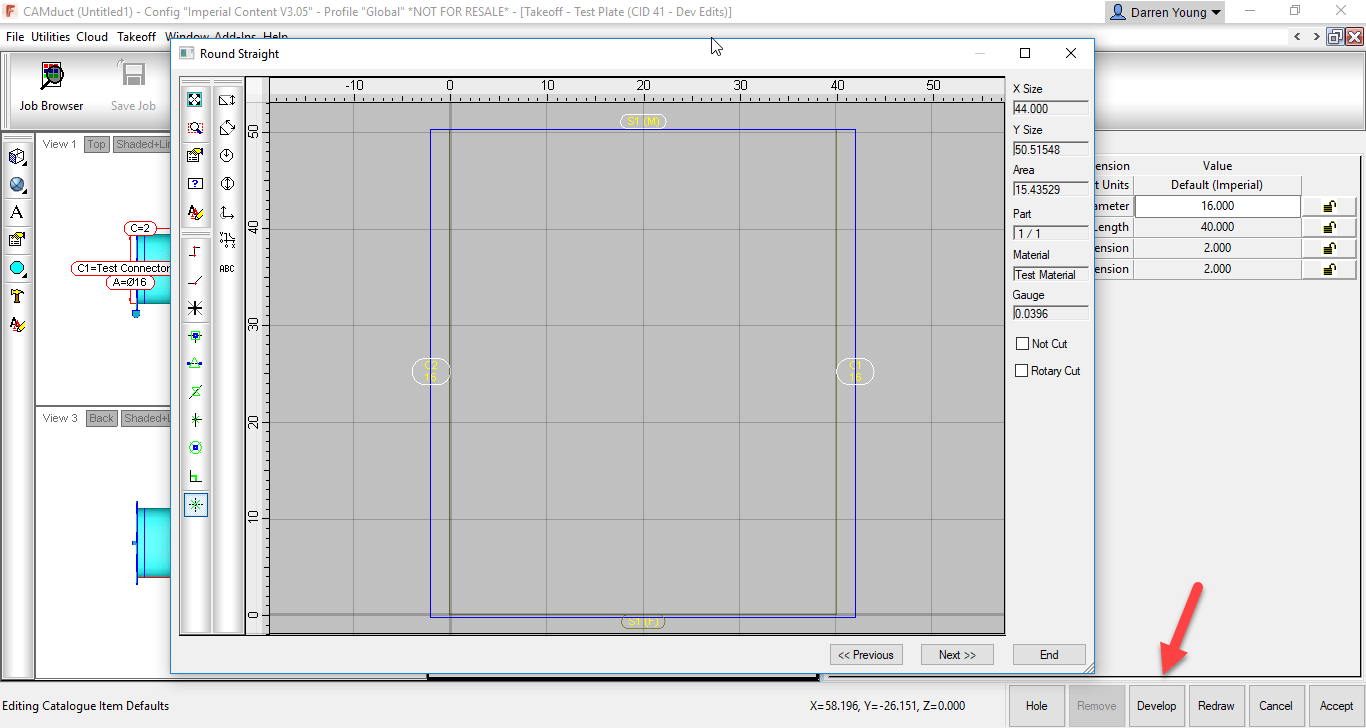
When you Edit the part in the ITM Editor, even if to change something simple as a material, the pattern gets redeveloped and the edits you made to the developments are lost. This makes ITM’s utilized this way very prone to getting wiped out of you’re not careful.

The solution to protecting these developments is to change them to a different CID pattern used exclusively for OPUS parts…CID 998 (or 0 depending how it’s created) OPUS parts contain only the development and not the originating ITM pattern. When you select the Edit option for an OPUS part, you go directly to the Opus Editor.


2) Proxy Database Entries

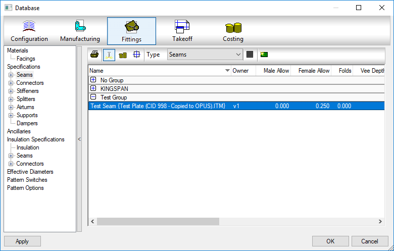
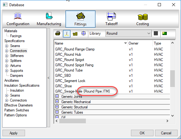
The other problem with edited developments is they can bring in proxy entries into your database. As an example, lets say the CID Pattern used was pointed to a Material, Connector or Seam in your database that no longer exists, was renamed or moved to a new group. As explained earlier, you can’t go back and edit the ITM to change them or your edits to the development will get wiped out.  You can change the seams/connectors/materials with a COD script to avoid this but most people are not familiar with this process. When you use this type of ITM, the old materials, seams and.or connectors that were originally used come back into your database with {brackets} around them.

Even then, a Development Part is assigned a material separate from the material on the ITM. There is no way to change the development part’s material from a COD script. You can however, change it from the Development tab of the Properties dialog.

The following image shows the Properties option when Right-Clicking on an ITM.
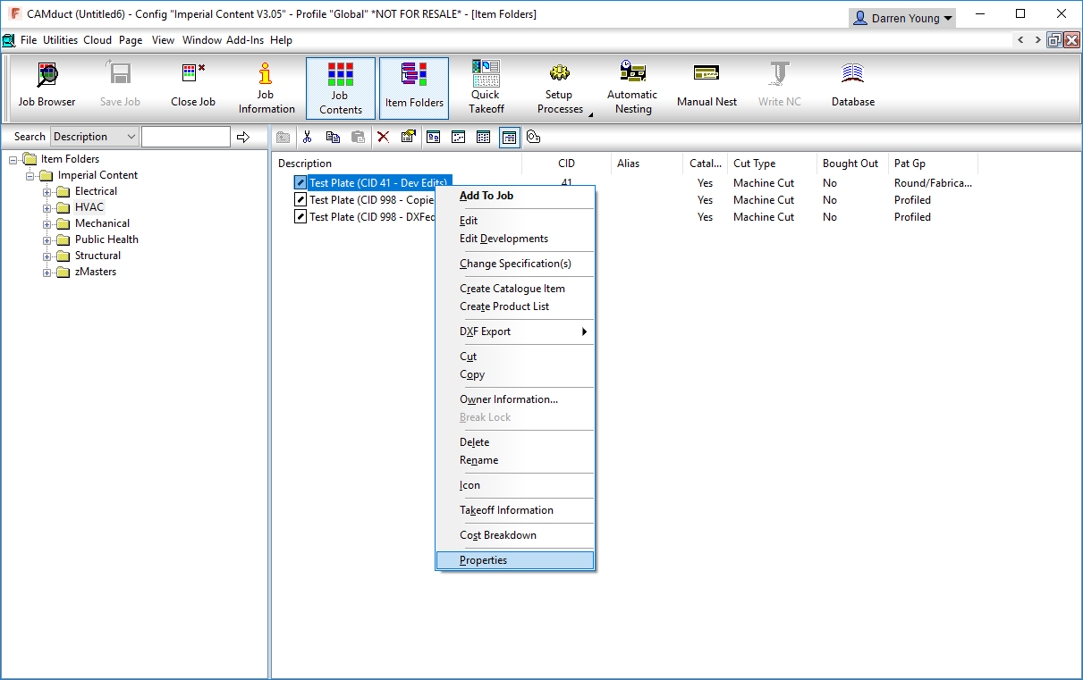
After clicking the Properties option, the properties dialog box will appear. Here, you can switch to the Developments tab to see the developments of the ITM. From this tab, you can then edit the Development Part material. This still presents a few possible difficulties…

  • You have to edit the development part material one ITM at a time.
  • You can’t script changing the development part material
  • You can’t set the development part material to “None” as this is not an option
  • Depending on the “Catalog” and/or other options of the ITM, the Development Part material drop down may not be enabled for selection.

As we mentioned earlier, a native OPUS part CID only contains the developments and avoids a lot of these issues.

The obvious thing to do is to go to the edited developments of the original ITM and copy the geometry to the Windows Clipboard (Ctrl-C). You could then go to an Empty OPUS part and paste the object there from the Windows Clipboard (Ctrl-V). But again, this presents yet more issues.

Even though you would only be copying/pasting the development entities, CAMduct still remembers there were seams and connectors applied and this data hitch hikes along for the ride on the geometry even though you can’t see it. Except now, you can’t get to the ITM editor any longer to change them and COD scripts can’t find any connectors to seams to change because an Opus part doesn’t have those options. The information i there,, hidden, but inaccessible.

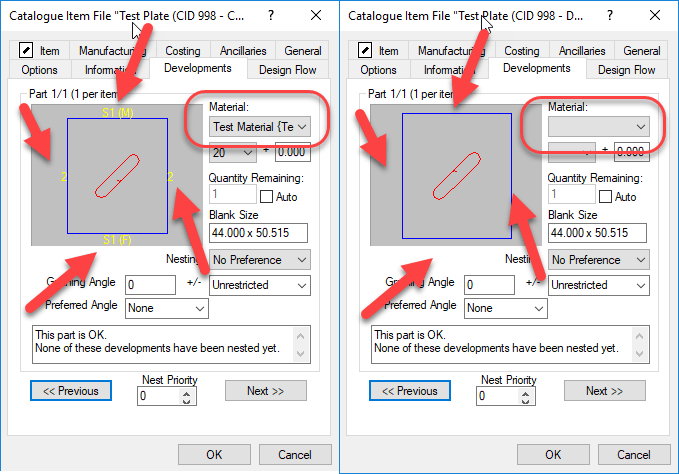
In the following image, you’ll see two ITM Properties dialog boxes side by side.

In the LEFT image, you’ll see what the Developments tab looks like on an ITM with edited Developments or even. It alo look this way on an OPUS part that was created using Copy/Paste method from a different CID. The OPUS Editor doesn’t show you, but the Developments tab in Properties displays text for the Seams/Connectors.  The image in the RIGHT is an OPUS part created with a completely different process that we’ll show shortly.

Also notice the image on the LEFT shows a material in the drop down list where as the image on the RIGHT does not. Using the ITM that was the source of the Left image will bring in proxy Materials, Seams and Connectors if they no longer exist in your configuration. Using the ITM that was the source for the Right image, will not bring in these Proxy items. This means if you later reorganize your materials/seams/connectors, the ITM for the left image will keep corrupting your database and the ITM for the right image will not.

The Solution

To resolve both of these issues, Edited Developments on none OPUS CID Patterns and eliminating proxy database entries, we can use the same process. This process involve creating DXF files for the existing ITM’s an then creating new ITM’s from those same DXF files.

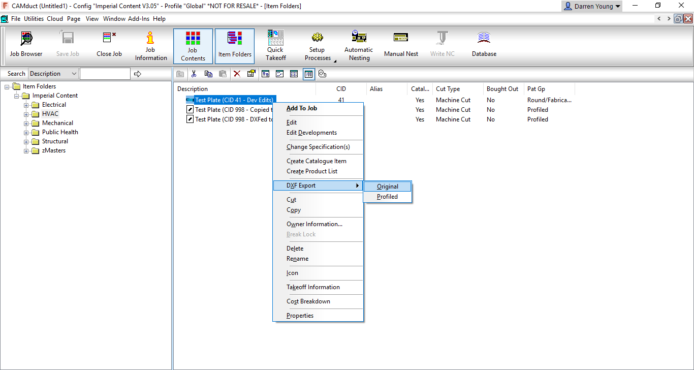
The following image shows how to Right-Click on the ITM and Export the DXF to a file on disk.
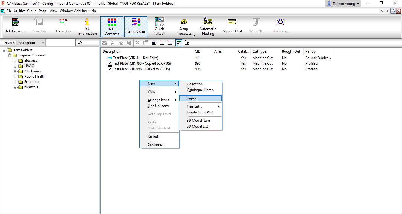
Once the DXF files are create, you can Right-Click on an empty area of the Folder display and select New, then Import as shown in the following image.
The import process is fairly self explanatory end leaves you in the Opus part editor. Here are can make any final changes and when clicking OK, you can overwrite the existing ITM or give it a new name. This new ITM is based on CID 998, has no material set in the developments and contains no traces of any seams or connectors. You also don’t need to worry about accidentally deleting the edited developments because editing this ITM brings you directly to the OPUS Part editor and does not bring you to the ITM editor.


Additional Considerations

What’s nice about the above process, is that you can select multiple ITM’s at one time to Export to DXF. And when you Import the DXF’s, you can also select multiple DXF files. There will be some additional or changed prompts in this process but it allows you to quickly clean up your existing OPUS parts and protect ITM’s made from non-OPUS CID’s.

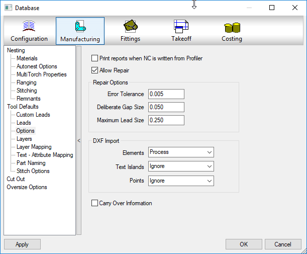
One thing to watch for is complex geometry with a lot of curves/arcs/lines. You’d typically see this type of geometry when cutting patterns that represent art or a lot of text. When dealing with this type of geometry, before you Import the DXF’s, you may want to explore some of the settings used by CAMduct to automatically detect a complete profile without any small gaps or overlaps causing issues, The following image shows where these settings can be made.

Use of these settings goes beyond the scope of this article so I’d recommend using a little trial and error to get the best results only if you encounter problems with importing DXF’s.
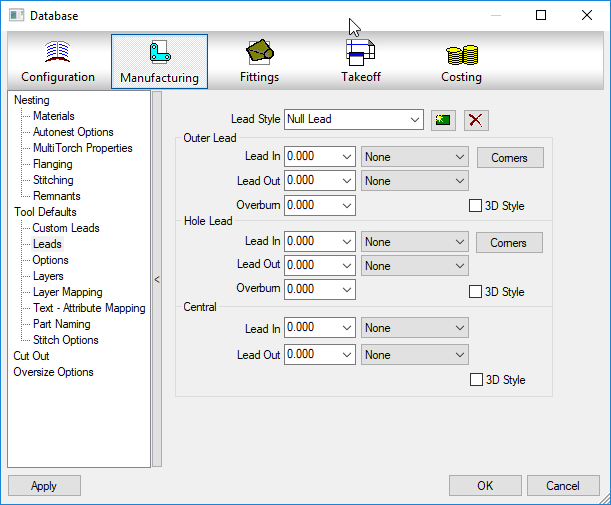
The other thing to watch for is the Kerf or offset used on the tools assigned to the profiled part and which types of lead in/out paths are used to start and end the profiles, While you can always edit these settings of the OPUS parts later on a case by case basis, you can set the defaults to use in CAMduct. The following image shows where to set these default values.

Taking a Closer Look

If you want to take a closer look, at the entire process, you can view the process this these two videos.

Here’s the process to cleanup a single ITM…


Here’s the process to cleanup a multiple ITMs…


If you want to play with a couple ITM’s yourself, you can download them here.

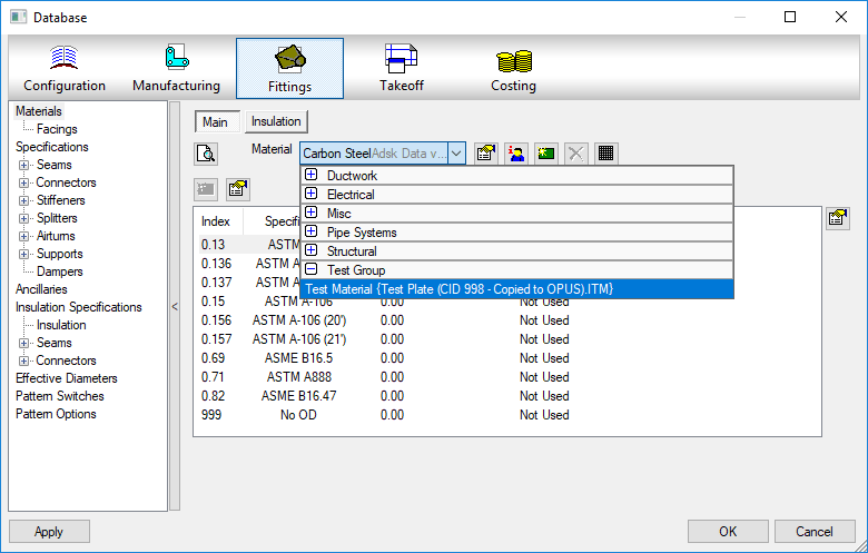
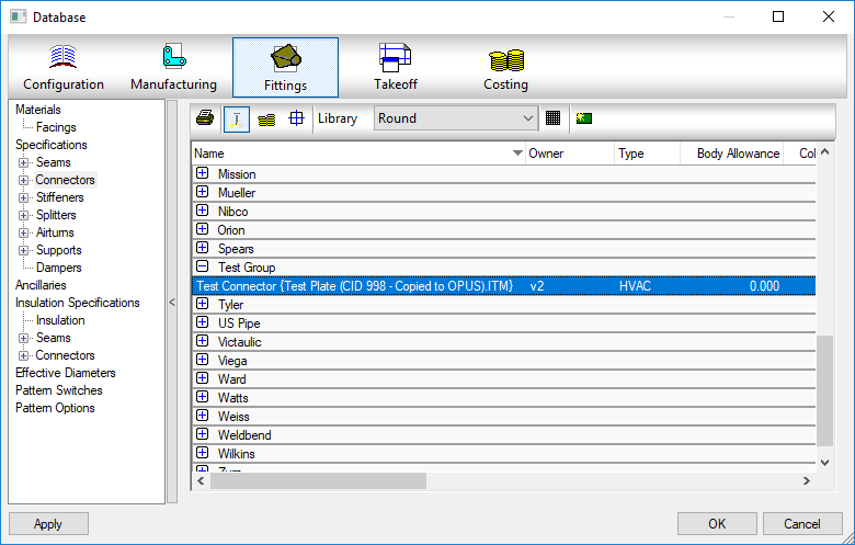
If you play with the original ITM Test Plate (CID 41 – Dev Edits).ITM or the OPUS part created with the flawed Copy//Paste method Test Plate (CID 998 – Copied to OPUS).ITM, you’ll see a custom Material, Seam and Connector added to your database, Delete them out and try again with the next ITM. You’ll see that the ITM created with the DXF process Test Plate (CID 998 – DXFed to OPUS).ITM we showed earlier does not bring the old materials, seams or connectors shown in the below images.
Autodesk Fabrication: Best Practice #3

Don’t leave proxy items in your fabrication database.

You’ll notice these as they appear with curly brackets { } around a piece of text like an ITM name or DWG name.

These proxy objects can show up many places. Services, Service Templates, Materials, Connectors, Seams, etc. They occur when an ITM or drawing containing ITM’s references a database entry that no longer exists in your Fabrication configuration. As an example, if you delete a connector from your database, let’s say “Copper Cup” then later add an ITM to your drawing that contains a reference to that connector, it gets added back to your configuration and displays the ITM name in the curly brackets.

If there’s bracketed items in your database they should either be made permanent or deleted. If deleted, they may keep coming back.  If you truly want them gone, you need to find the objects bringing them back and update them to the new item in your database configuration that they should point to.

A properly managed Fabrication database configuration should have everything configured properly. Items with curly brackets are an indication that things are not configured properly.

Future posts will explain various techniques to help identify where these bracketed items come from as well as how to correct them efficiently.


Free / Low Cost Autodesk Software

Ever wish you could have access to Autodesk software at home? Well, you can. There’s several ways depending on your situation. Here’s how…


Free: 30-Day Trial

Most Autodesk software allows you to download and install a 30-day free trial. Simply go to Autodesk’s web site and download what you’e looking for.

https://www.autodesk.com/products


Free: Licenses for Students and Educators

Autodesk allows students and educators free access to Autodesk software. You can find more information from your school or from Autodesk’s web site.

https://www.autodesk.com/education/home


Free: Home use Licenses from your Employer.

Autodesk allows employees home use licenses of software to use at home while that are not at work. Your company’s contract manager or software coordinator will need to work with you to get you access. I they are unsure of the rules, your Autodesk reseller can help answer their questions. More information can be found on Autodesk’s web site.

https://knowledge.autodesk.com/customer-service/account-management/software-downloads/home-use


Low Cost: AUGI Professional Membership w/ADN Access

The Autodesk User Group International (AUGI) has negotiated and agreement with Autodesk where you can get an Autodesk Developer Network (ADN) Standard membership when you purchase a $100 AUGI Professional Membership.

Autodesk Developer Network is the program where commercial developers, corporate developers and independent developers can get access to Autodesk’s software for development purposes. Note that you may need to Email AUGI after signing up to get details on how to apply for the Autodesk ADN membership. This information was not provided proactively by Autodesk when I signed up. Because the ADN membership is geared toward developers and authors, the application process asks for a lot of information that’s not relevant in the case of those gaining access from AUGI so you’ll want to follow AUGI’s instructions for applying and fill out the information as best you can. You can get more information from AUGI’s web site.

https://www.augi.com/join

30 Days of Free Autodesk training on Lynda.Com

Lynda.Com is offering a 30 day free trail for over 350 different Autodesk related courses. You can sign up here…

https://www.lynda.com/Autodesk-training-tutorials

Lynda also as a lot of other courses for many topics. Before you spend you money on a subscription, check with your local library. Many library systems have agreements with Lynda.Com to offer courses for free to their members. King Country Library System (Seattle Washington), Multnomah County Library (Portland, Oregon) and the Salt Lake City Library (Utah) are just some of the many libraries offering these courses on Lynda.Com for free.


Autodesk Fabrication: Best Practice #2

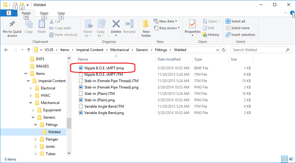
Don’t use BMP files for ITM Images

If you’ve been using an Autodesk Fabrication configuration for a long time, like back before Autodesk acquired MAP Software Ltd, you may have a lot of content that’s using Bitmap (*.BMP) files. These image files are used on a couple key locations….

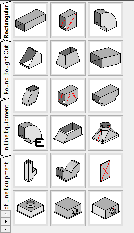
1: Service Palettes….

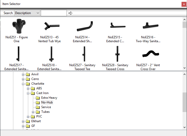
2: Folders Dialog….

If you’re Fabrication configuration uses BMP files for images, you should consider converting them to PNG files. There’s a number of utilities that will do this in bulk for you if you have a lot. My favorite is using TechSmith’s SnagIt Editor but there are others.

Use Windows Explorer and browse to your content. You can use the search functionality in the upper right corner and search on *.BMP to see how many Bitmap images there are. Or you can browse folder by folder looking for them. Hint: Sorting by type can speed with this too.

Once you convert the BMP’s place the PNG files in the same folder using the same name as the BMP and then delete the BMP files. Doing this will reduce the size of the files which in turn speeds the display of your service palettes and folder’s list.

Autodesk Fabrication: Best Practice #1

Don’t use Double Quotes ( ” )….Ever.

An Autodesk Fabrication Configuration contains a lot of information. One of the best tools for managing, sorting, filtering and maintaining lots of information is Microsoft Excel. There are some functions in Fabrication that export information into CSV format. Commands like SYSSCRREPORT in CADmep. You may even have some scripts or API code that exports data to a CSV.

When Double Quotes are used, this can and does often confuse Excel into thinking that it’s a separator between multiple pieces of Text and it can shift the data in some rows to different columns.

If you use feet-inch format/units and like the look of double quotes for inch marks, an easy workaround is to use 2 single quotes ( ” ) as opposed to a single double quote ( ” ). When using 2 Single Quotes, it’s hardly noticeable even when looking for it like in this text. Try selecting the text sand you’ll see they are indeed different.

While this rule should be adhered to anywhere in the fabrication database, there’s 4 primary areas where it’s most likely to cause you grief.


Database Entries – Materials, Specification, Connectors, Seams, Airturns, Ancillaries, etc.


Folder and ITM Names – While a perfectly valid character in Windows for files and folders, it’s not a good idea when using Autodesk Fabrication.


Product List Names – One of the most common areas to see the inch mark.


Product Information Editor – Another common location where you’re tempted to add double quotes. It’s common for people to maintain this data in Excel in the first place so it’ll be really easy to do a global search and replace to fix it.


In future posts, I’ll share some processes and scripts that can be affected by using Double Quotes. Until then, just trust that it’s a bad idea.

Programmer’s Trick: Custom Number Rounding

Most programming languages have a function to round a number to the closest whole number using standard math rules. Anything fraction of a number < 1/2 typically rounds down and any fraction of a number >= 1/2 rounds up. In Visual Basic, there’s a “Round” function, C# has a “Round” method and Excel even has a “Round” function.

  • 1.0 already a whole number, rounded value remains 1.0
  • 1.25 rounds DOWN to 1.0
  • 1.49 rounds DOWN to 1.0
  • 1.5 rounds UP to 2.0
  • 1.75 rounds UP to 2.0
  • 2.0 already a whole number, rounded value remains 2.0
  • …etc…

Some languages lisp AutoLISP, doesn’t have a function that behaves like this. Instead, AutoLISP had a “FIX” function that rounds down, regardless of the fractional component.

  • 1.0 already a whole number, rounded down remains 1.0
  • 1.25 rounded down becomes 1.0
  • 1.49 rounded down becomes 1.0
  • 1.5 rounded won becomes 1.0
  • 1.75 rounded down becomes 1.0
  • 2.0 already a whole number, rounded down remains 2.0
  • …etc…

If you use a language like AutoLISP that only drops the fractional component of a number (essentially always rounding down) to function like real math rules, this is easily accomplished by simply adding 0.5 to the number before rounding. This changes the resulting rounded number to the same as traditional mathematics would round the numbers.

  • 1.0 + 0.5 = 1.5 rounded down becomes 1.0
  • 1.25 + 0.5 = 1.75 rounded down becomes 1.0
  • 1.49 + 0.5 = 1.99 rounded down becomes 1.0
  • 1.5 + 0.5 = 2.0 rounded down becomes 2.0
  • 1.75 + 0.5 = 2.25 rounded down becomes 2.0
  • 2.0 + 0.5 = 2.5 rounded down becomes 2.0
  • …etc…

So far, this is quite simple. But what if you wanted to round to the nearest 1/8? Or 1/2?  Again, many of the rounding functions in programming languages have the ability to round to a certain number of decimal places by specifying the number of decimal places as an argument to the rounding function. This works great on decimal values where you want to round to the nearest 1/10 (0.1), or 1/100 (0.01). However, this doesn’t work in other fraction that are not base 10. Rounding to the nearest 1/8 yields 3 decimals (0.125) but 2/8 (1/4) yields 2 decimal places (0.25) and 4/8 (1/2) yields in 1 decimal place (0.5). So how is this done?

Quite simply actually. You can use another technique which shifts the decimal. This moves the fractional component you want to keep to the left of the decimal and leaves the remaining fractional components to the right of the decimal where you can round them off. It sounds more complicated than it is.  Let’s look at how this works by focusing on 1/8 (0.125).

What happens when we multiply 1/8 (0.125) by a factor of 8? We get 1.0 which when rounded, stays 1.0, we then divide by 8 again which shifts the decimal back to where it belongs and we end up with out original number as follows…

0.125 * 8 = 1.0  rounded stays 1.0 / 8 = 0.125 (1/8)

Now let’s try this when the number is slightly larger….

0.126 * 8 = 1.008 rounded becomes 1.0 / 8 = 0.125 (1/8)

The key is…if you want to round to the nearest 1/8, you “MULTIPLY by 8, ROUND, then DIVIDE by 8″.  You can also use the inverse formula “DIVIDE by 1/8, ROUND, then MULTIPLY by 1/8″. Either formula works.

The same technique works if you want to round to the nearest 2 (even) or 3 (3, 6, 9, etc.).

  • 0.25 / 2 = 0.125 becomes 0.0 * 2 = 0.0
  • 0.5 / 2 = 0.25 rounded becomes 0.0 * 2 = 0.0
  • 1.0 / 2 = 0.5 rounded becomes 1.0 * 2 = 2.0
  • 1.99 / 2 = 0.995 rounded becomes 1.0 * 2 = 2.0
  • 2.00 / 2 =  1.0 rounded becomes 1.0 * 2 = 2.0
  • 2.99 / 2 = 1.495 rounded becomes 1.0 * 2 = 2.0
  • 3.0 / 2 = 1.5 rounded becomes 2.0 * 2 = 4.0
  • 3.5 / 2 = 1.75 rounded becomes 2.0 * 2 = 4.0

Using these techniques, you can quickly convert numbers into the rounded format of your liking, regardless of the programming language you use.

AutoCAD Selection Modes

AutoCAD does a lot of things for you automatically. Unless you’re an old timer from back in the DOS days, you may not be familiar with all the options you can choose from when presented with the “Select Objects:” prompt in AutoCAD, In days of old, AutoCAD displayed all of the options on the command line when going into selection mode. There were less options back then and a lot of what happens automatically now, you had to type the options for,

Today, there’s a lot more options so AutoCAD no longer displays them unless you type an invalid entry. Even then not all the options are displayed. Many of the options now are default behavior making the options less critical in operating AutoCAD efficiently. None the less, they are often helpful. Here’s a chart of the options available. A description of each option follows. For more detailed information, you can refer to AutoCAD’s Online Help using the following link.

AliasOptionModal / Single Use
AAddModal
ALLEverythingSingle Use
AUAutoModal
CCrossingSingle Use
CPCrossing PolygonSingle Use
GGroupSingle Use
LLastSingle Use
MMultipleModal
OObjectModal
PPreviousSingle Use
RRemoveModal
SiSingleModal
SUSub-ObjectModal
UUndoSingle Use
WWindowSingle Use
WPWindow PolygonSingle Use
  • Add (A) – Default mode for selection in AutoCAD. As you repeatedly pick items, they are ADDED to the selection set you are building. Stays in effect until switching to REMOVE mode.
  • All (AL) – Single use option that selects ALL objects in your AutoCAD drawing even if not displayed outside the current drawing area. Object on layers that are OFF and/or LOCKED will still be selected. Objects on layers that are FROZEN will not be selected.
  • Auto (AU) – Default mode for selection in AutoCAD. It’s combination of two other AutoCAD selection modes combined. SINGLE if you pick on an object, it will be selected. If you don’t pick on an object, BOX selection mode will be a CROSSING if the second point is to the left of the first selected point or a WINDOW selection  if the second point is to the right.
  • Crossing (C) – Single use selection mode where you pick two points to form a rectangle. Anything completely within or crossing the rectangle, regardless of the order or direction the points are picked is selected.
  • Crossing Polygon (CP) – Single use selection mode where you picks a series of points to form a polygon. Any object completely within or crossing the polygon will be selected.
  • Group (G) – Single use selection mode that allows you to type the name of a group to add the objects in that group to your selection. When specifying the names of unnamed groups, you must include the asterisk (*) prefix in the automatically assigned anonymous name AutoCAD gives it.
  • Last (L) – Single use selection mode that allows you to select the most recently added object in the drawing that’s visible, in the current drawing space and who’s layer is not off or frozen.
  • Multiple (M) – Modal selection mode used to selects objects individually without highlighting them for performance when selecting complex objects. When finished selecting objects you don’t want to highlight, press Enter and you’ll be returned to the default AutoCAD selection mode and still in the select objects prompt.
  • Object (O) – Default selection mode in AutoCAD where you select objects. Use this option to exit the SUBOBJECT selection mode.
  • Previous (P) – Single use selection that selects everything that was in the previous selection set (assuming the previous selection set wasn’t erased).
  • Remove (R) – Modal selection mode that cancels the default ADD mode to remove objects from your selection set. Most useful when it’s faster to select everything (ALL) and remove what you don’t want selected than it is to select everything you do want selected.
  • Single (Si) – In addition to being a single use selection modem, you can only select one object and the select objects prompt is terminated. If you fail to select an object in SINGLE mode, you are switched to BOX mode.
  • SubObject (SO) –  Model selection that allows you to select edges, faces, etc of complex objects. When in SubObject mode, you can no longer select Objects without using the OBJECT option to return to that selection mode.
  • Undo (U) – Single selection mode that removes the most recently added object (or objects if they were selected as a group) from the selection you’re building. Can be used repeatedly to keep removing object(s) in the reverse order they were added.
  • Window (W) – Single use selection mode where you pick two points to form a rectangle. Anything completely within the rectangle, regardless of the order or direction the points are picked is selected. Unlike CROSSING, anything that crosses the window will not be selected.
  • Window Polygon (WP) – Single use selection mode where you picks a series of points to form a polygon. Any object completely within the polygon will be selected. Unlike CROSSING POLYGON, anything that crosses the polygon will not be selected.