Autodesk Fabrication Scripting resources have had a few updates more updates. Believe it or not, the 22 ADD/REMOVE functions that apply to ITM Product Lists have been on my “Undocumented Functions To Research” list for over a decade. I’ve finally gotten around to figuring out how they work and documenting. Here’s a summary of the changes…
I’ve made a couple updates to the Autodesk Fabrication script libraries. If you use them, you can download updated versions from here.
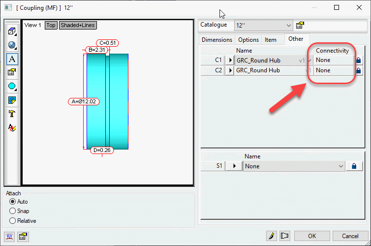
Scripts have been updated to include the Connector Material property found on CID/Patterns 522, 1522 & 2512 as shown below…
This property is intended to be used by a connector to specify a alternate material the connector can connect to. This allows a coupling to connect to alternate materials such as with transition couplings.
I have updated the Autodesk Fabrication COD Scripting resources. Resources have also been reorganized. Everything is still there but you may have to navigate to it differently.
Most of the updates are additions to the COD Scripting reference. They now include all the information that was in my Advanced Scripting sessions at MEP Force and Autodesk University.
A complete list of all COD Scripting resources can be found here. The COD Language reference is a complete list of all properties, functions, operators, keywords, and anything else scripting that I’m aware of. Everything I know about COD Scripting both documented and undocumented is located here. If you notice properties or functions in COD scripts of yours or from others that is not listed here, please let me know. I’d love to add anything new you find.
I didn’t plan up updating scripts again so soon but I found a couple more undocumented properties. I thought I’d post them sooner rather than later.
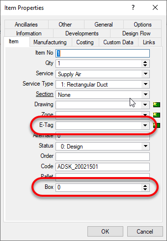
The two ITM properties I found are “BOX” and “E-Tag“.
BOX is only visible from CAMduct. It’s intended purpose appears to be for specifying a “Box” for the ITM in question for shipping purposes but you could use it or anything. Despite it being visible only in CAMduct, using COD Scripts, you can read and write it from ESTmep or CADmep too.
E-TAG is visible from any of the Fabrication products. It’s used for Equipment Tags. You can see both properties from here if in CAMduct or only E-Tag is ESTmep or CADmep.
Scripts Updated
All Debug Scripts – Nothing major, just formatting in the comments section.
WriteAll_Props (Job).cod – Updated to support BOX & E-TAG properties.
WriteAll_Props (Library).cod – Updated to support BOX & E-TAG properties.
I’ve made a couple updates to the Autodesk Fabrication script libraries. If you use them, you can download updated versions from here.
Scripts Updated
Debug
Debug ITEM Library.cod
Debug ITEM Sealant.cod
Job Items
WriteAllLibrary (Job).cod
WriteAllSealant (Job).cod
WriteAll_Props (Job).cod
Library Items
WriteAllLibraries (Library).cod
WriteAllSealant (Library).cod
WriteAll_Props (Library).cod
Issues Corrected
Issue 1: Scripts accessing the “Library” property were failing on CID/Pattern 2199. Scripts have been updated to watch for this and report it as an ‘Unknown‘ Library.
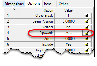
Issue 2: Some CID/Patterns can be configured to be pipework or duct work depending on the “Pipework” option’s “Yes/No” status. Scripts were updated to properly report or ignore this property depending on the Sealant value being present.
If the option is set to “Yes“, the pattern is a pipework item. If set to “No”, the pattern is a sheet metal item. Sheet metal items contain the “Sealant” property where as Pipework items do not.
This condition is present in the following CID/Patterns…
149
838
902
1101
1238
1239
1240
1241
1242
1247
1248
Special thanks to Kyle Speropoulos of MMC Contractors in Kansas City for alerting me to this issue.
Have you ever received a list of coordinates in a CSV file and wanted to place those in AutoCAD? Were you aware this can take as little as 2 minutes?
For a very long time, AutoCAD has supported SCRIPT files. A script file is nothing more than a text file (using only Notepad) that lists the everything that you’d typically type to AutoCAD’s command line.
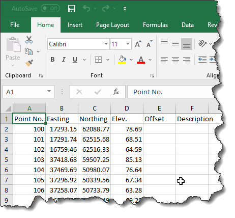
Take for example the following CSV file. How would we get this into AutoCAD?
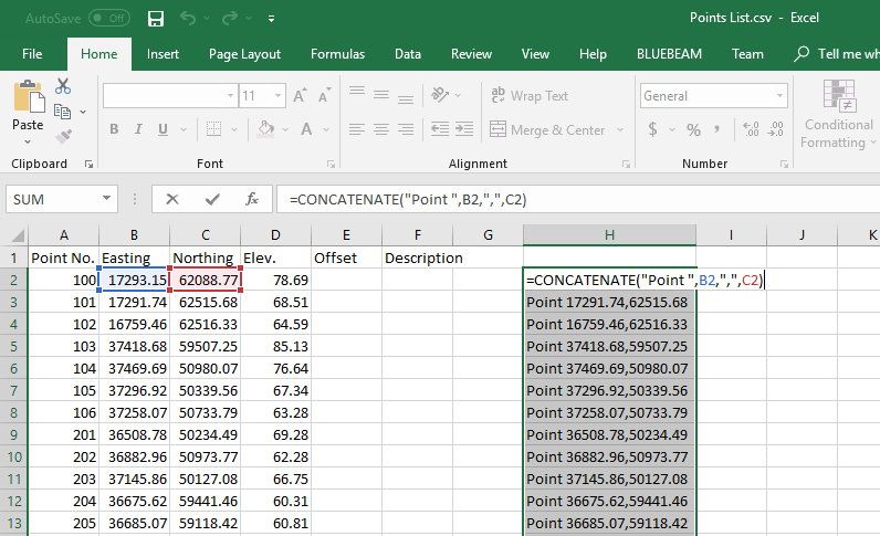
Points List in CSVFormat Opened in Excel
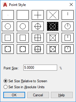
To figure out what we need to type in AutoCAD, let’s first start by making sure our Point style is something other than a single dot so it’s more easily visible on your screen. To do this, type “PTYPE” at AutoCAD’s command line. If you don’t get the following dialog, Escape out of the command and type “DDPTYPE” and try again. Select a point style that suites you.
Point Style Dialog
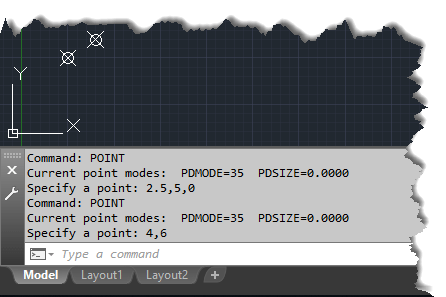
Now that you have a point style that’s more visible on the screen, lets type the Point command and see what input it takes.
You can see from the below image of the command line that once we type “POINT” and press ENTER or SPACEBAR, there’s a little text that displays the current point style and size. You’re then prompted for the coordinates. The points in this example were entered by typing X,Y,Z coordinates for one point and X,Y coordinates for the other. After typing the coordinates and pressing ENTER, the command completes.
X,Y or X,Y,Z Formats Can Be Used For Points
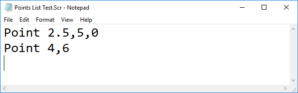
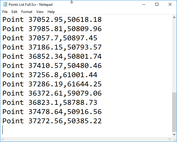
To test this theory, we can use Notepad to manually create a Script file. Type the contents you in the below image and name your file with an “SCR” File extension. You’ll want to make sure Notepad’s “Save as type” drop down list is set to “All Files (*.*)” or else Notepad will append a TXT to the end of the file.
One other thing to also note is that the cursor is after the last line, just below it. This is because there’s an “Enter” after the last point…this is just like hitting Enter on the keyboard to complete a command in AutoCAD.
Use Notepad to Create a Script File
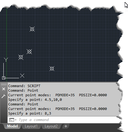
After you’ve created your text file, type the “SCRIPT” command at AutoCAD’s command line and select the Script file you just created. When complete, AutoCAD should have added 2 more points to the drawing.
The Script File’s Input Looks The Same As Manually Typing.
So, now you know how the basis for a script file (same as you’d type manually) and how to create one (using Notepad), the next thing you need to do is convert the CSV file in Excel to a Script file. That’s actually quite simple.
You’ll use Excel’s “CONCATENATE” function which takes several pieces of text and puts them together. In this example, this is the formula we’re using…
=CONCATENATE("Point ",B2,",",C2)
The first piece of text is the Point command. Remember, we can use the SPACEBAR after a command and it’s the same as if we’re pressing the ENTER key. That’s why you see the space after the “POINT“. Each piece of typed text is also contained in double quotes.
=CONCATENATE("Point "
Each piece of text that is concatenated is separated by a comma. After the command, you start typing the X-Coordinate which is the Easting column in the CSV file. Because we’re not explicitly typing text, we can simply use a cell reference like so…
=CONCATENATE("Point ",B2
When typing coordinates in AutoCAD, we separate them with a comma, so we use another comma for Excel’s Concatenate function, then a comma explicitly typed in double quotes.
=CONCATENATE("Point ",B2,","
Finally, we add the Y-Coordinate which is in the Northing column using a cell reference, again, remembering to separate all the pieces of data with a comma and close the Excel function with a closing parenthesis.
=CONCATENATE("Point ",B2,",",C2)
When you’re done, copy the formula to the other cells. You can see in the image, that we have a line of text similar to what we typed in Notepad manually the first time. The below image, I’ve used the F2 key to edit the first cell so you can see the formula and the cell references.
Excel Used to Build a Script File
Now that you’re text in Excel is in a Script File format, you can guess the next step. Copy/Paste the text into Notepad, Save with a TXT extension on the file name.
Make Sure the Cursor is on the Last/Empty Line
The last step is to run the script file in AutoCAD using the Script command. Zoom Extents in AutoCAD to see your points. The CVS file, Excel File and Script files can be downloaded for examination from this link.
Here’s a screen recording of making and running the script file. As you can see, it takes a CSV file, gets converted into a Script file and places the points in AutoCAD in less than 2 minutes.
CSV Points List to AutoCAD Points in Less Than 2 Minutes
Script files are quite easy. You could easily add more text, and use different commands to do the same thing like Insert an attributed block into the drawing and use the point number as the attribute value. You just need to make sure all your system variables are set to prompt you upon insertion for the attribute value.
The only real downside to Script files is they’re not intelligent. They don’t like extra characters or spaces, the don’t work well with commands that prompt for user input or display dialog boxes and they don’t perform conditional logic to do different things depending what they find. They will however call AutoLISP routines so when I have more advanced work I want to do in a script file, I just have the Script call and run my Lisp as well.