I’m occasionally asked how one would add one of every size in a product list to their job. This very easy using ESTmep or CAMduct. CADmep however does not have this capability.
Here are the steps….
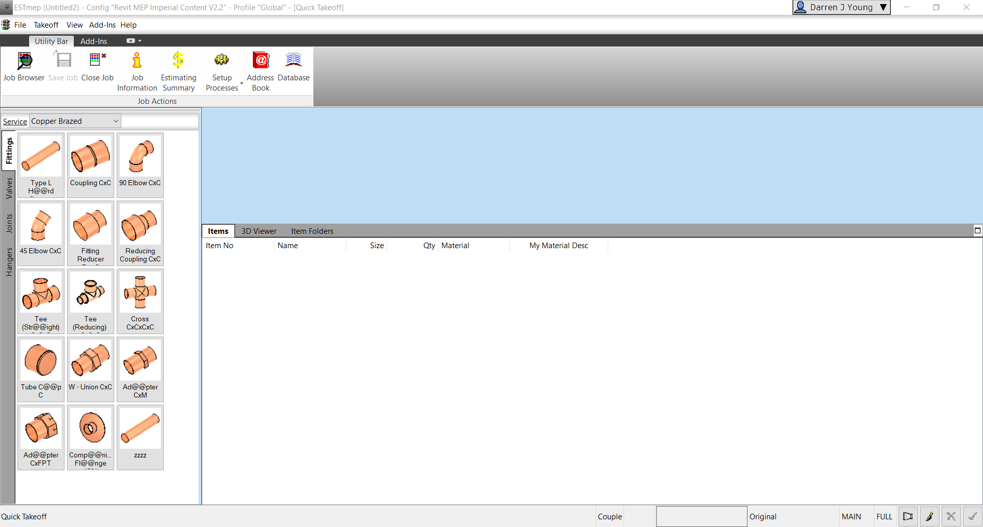
Step 1: Start ESTmep / CAMduct with a blank job.
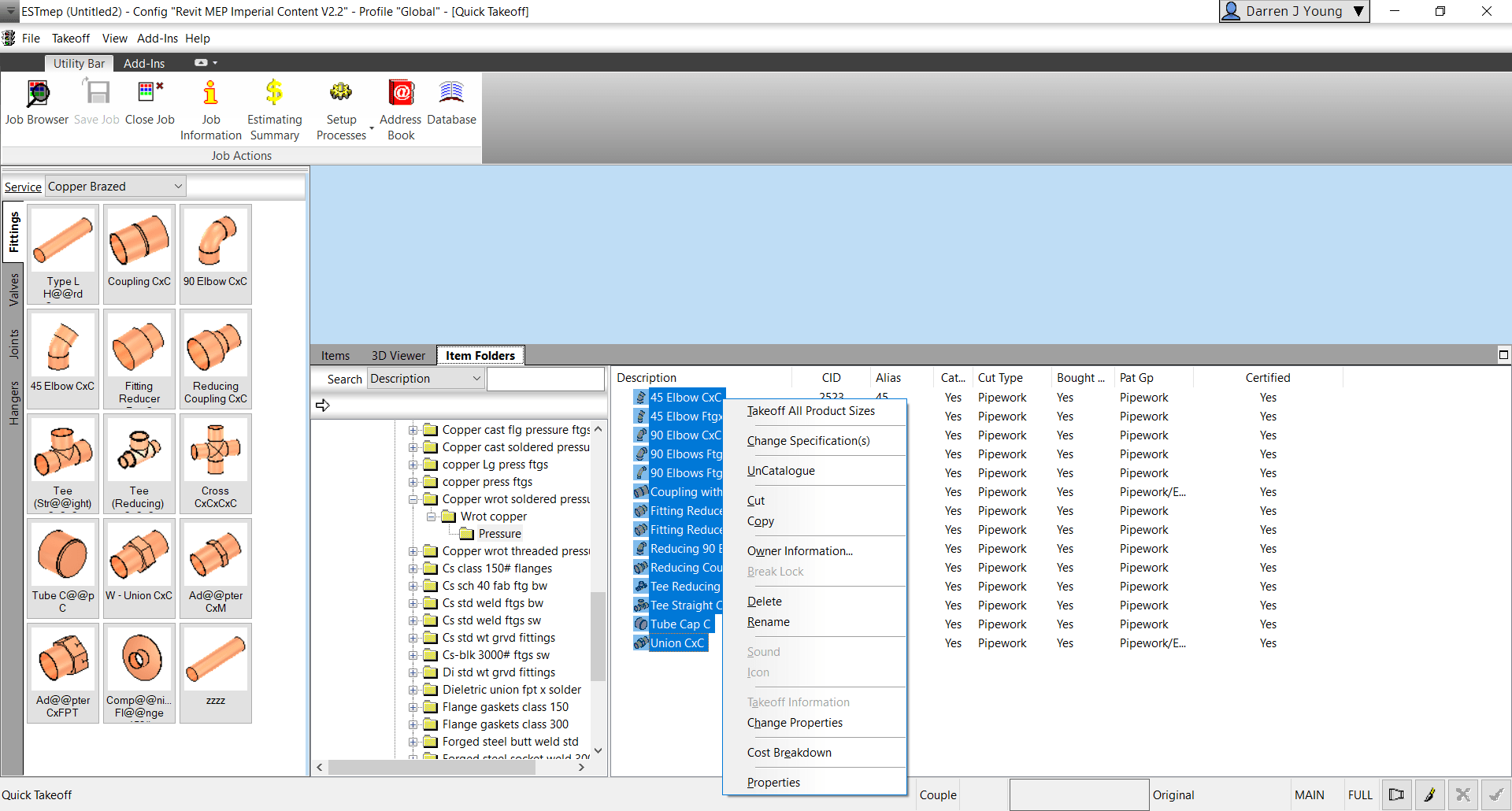
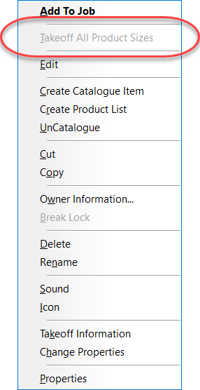
Step 2: Go to Item Folders and navigate to the folder with the ITM(s) you wish to takeoff all sizes for. Select all the ITM’s and press CTRL+SHIFT+Right-Click and select Takeoff All Product Sizes.
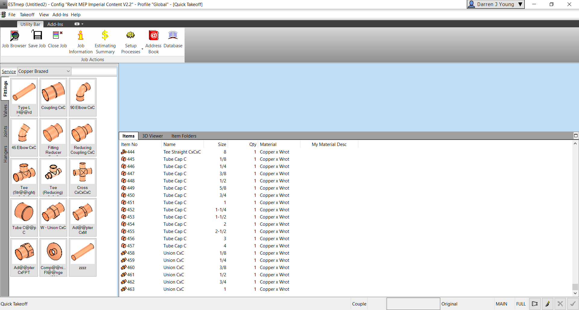
Step 3: Go back to the Items tab and review all the sizes of each item you selected.
Why Would You Do This?
There’s several reasons this may be helpful to you.
Any Size with dimensional errors is quickly found
A simple report shows you where you may have holes in your data (Price, Labor, Product Info, etc.)
Produce a quick MAJ that can be opened in CADmep (OpenJob) to measure each size to ensure dimensional accuracy.
If the option is grayed out/disabled, you’re one or more of the ITM’s in your selection is NOT Product Listed. For this to work, all items you’ve selected must be Product Listed.
I’ve added graphics to better illustrate the Autodesk Fabrication Object Model for COD Scripting,
If you write COD scripts for CADmep, ESTmep or CAMduct, this can help you better understand how the various properties and objects are structured when you write your code.
If you want to learn more about Fabrication COD Scripting and how to use these resources, register for MEP Force 2021 and look for my Fabrication Scripting sessions.
You can find links with the other Fabrication COD Language Reference items here…
If you’ve not downloaded the Autodesk Fabrication Script Libraries lately, you might want to grab an updated copy. There’s been several updates over the last month. Here’s what’s changed…
DamperRotation Property (undocumented) has been added to all Debug, Job and Library scripts. Support for this property was added in 2017 but never documented. It’s there to support the rotation of Dampers on Fabrication Parts in Revit. It should be noted, that this value is Added to the Angle property of the assigned damper. As such, it acts as an Adjust and not an Override. e.g. Damper w/Angle of 90 + Rotation Property in the ITM of 90 results in a damper rotated 180 degrees.
StiffenerGroup Property added to the Autodesk Fabrication 2022.0 and later versions of the Debug, Job and Library scripts.
AirturnGroup Property added to the Autodesk Fabrication 2022.0 and later versions of the Debug, Job and Library scripts.
SplitterGroup Property added to the Autodesk Fabrication 2022.0 and later versions of the Debug, Job and Library scripts.
InsulationStatusLock Property added but listed as “Unavailable” as it stopped working in 2017. Added in the hopes it gets fixed in future versions.
StructureType Property added to the Autodesk Fabrication 2022.0 and later versions of the Debug, Job and Library scripts. Property was “Write Only” in 2021 and prior versions so was unable to display in prior versions.
Product ListHasCustomData Property has been added to all Debug, Job and Library scripts.
Product ListHasFlow Property has been added to all Debug, Job and Library scripts.
ItemPCFSKey Property has been added to all Debug, Job and Library scripts.
ItemCostByLength Property removed from Material Debug scripts (never really belonged there).
Setting up Autodesk Fabrication to communicate with a TigerStop isn’t difficult. But there really isn’t any good resources that explain how to do it. I’ve explained it multiple times to multiple people so I thought it might make sense to document it here.
This following instructions are not needed of you’re using a system like GTP Stratus or MSuite (formerly FabPro1) as they have their own process for interfacing with TigerStops. However, you can easily run a TigerStop from Autodesk Fabrication without buying any additional software. All you need is a TigerStop and Autodesk Fabrication.
Step 1 – Install TigerLink
From Autodesk Fabrication, you’ll be exporting CSV files. TigerLink is a free software from TigerStop that will take those CSV files and break them down and reformat them into files your Tigerstop software can use.
You can get TigerLink software from TigerStop.Com. Go there and search for “TigerLink” and download the latest version (6.x used in this documentation).
Once installed, you’ll notice a TigerLink folder on your desktop…
And an icon in your system tray…
Right-Click on the TigerLink icon in your system tray and select Open. This will display the following dialog. TigerLink can do several things but we only want it for one purpose. You’ll want to ensure the Auto Connect toggle is Unchecked so that TigerLink does not look for a TigerStop machine.
Be default, TigerLink runs automatically when you start your system and clearing this toggle will prevent it from warning you that there was no machine found. If you don’t want it to run automatically, remove the shortcut it places in the Windows Startup folder.
For now, close the dialog. Then, Right-Click on the system tray icon again and choose Exit. We don’t want the software running when we do our initial configuration a little later.
Step 2 – Creating Your Fabrication Export (Items)
For Tigerstop to work, you need to export data from Autodesk Fabrication. Tigerstops need a minimum of 2 pieces of information. One is a length (decimal format) , the other a quantity. That’s it. However in practice, you’ll want a little more information.
Cutting Pipe is one of the primary uses for TigerStop. So we need to configure a CSV export to do this. But let’s also plan the data we want. We may want to export all types of pipe and sizes in a single export. But you can’t cut mixed materials or sizes from the same stock. So we’ll need material and size in our export so TigerLink can use those fields to break down the data. Let’s breakdown our list of data fields here that we’ll want to send to the TigerStop….
Number
Property
Purpose
0
Item CID
This won’t be output but is used in the Report to filter the Exports to CID 2041 (pipe) only.
1
Item Quantity
Required by TigerStop
2
Item Centerline Lenth
Required by TigerStop. Must be decimal.
3
Job File Name
May be helpful in the TigerTouch display for the operator
4
Item Number
We want to know the piece number for a label
5
Item Description
This typically holds the “Size” of pipe in product listed ITMs. e.g. 1/2″, 3/4″, etc. TigerLink will use this data so files are separated by “Size”. We’ll also use it on the label.
6
Item Centerline Length
We’ll include this again formatted in Ft-Inch for the shop guys who may want that on the labels
7
Item Material Name
Tigerlink will use this data so files are also separated by material name. .e.g. Copper vs PVC vs Cast Iron, etc.
8
Item Spool Name
We’ll want this on the label too.
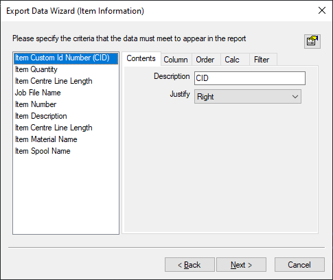
Use the CSVEXPORT command in CADmep to create your export report. When done, your report configuration might look like the following….
When your report is done, the resulting data might look like the following. Notice how all the sizes and materials are mixed together. This is what TigerLink will fix for us.
Qty,Length,Job Name,Item No,Description,Length,Material,Spool
1,39.146,Sample Data Export,12,4'',3'-3 1/8",Pipe Systems: Cast Iron,
1,40.421,Sample Data Export,12,4'',3'-4 3/8",Pipe Systems: Cast Iron,
1,48.250,Sample Data Export,12,4'',4'-0 1/4",Pipe Systems: Cast Iron,
1,11.835,Sample Data Export,12,4'',11 7/8",Pipe Systems: Cast Iron,
1,42.242,Sample Data Export,10,2'',3'-6 1/4",Pipe Systems: Cast Iron,
1,21.542,Sample Data Export,10,2'',1'-9 1/2",Pipe Systems: Cast Iron,
1,18.024,Sample Data Export,8,2'',1'-6",Pipe Systems: Cast Iron,
1,35.939,Sample Data Export,6,3'',3'-0",Pipe Systems: PVC,
1,22.101,Sample Data Export,6,3'',1'-10 1/8",Pipe Systems: PVC,
1,22.101,Sample Data Export,6,3'',1'-10 1/8",Pipe Systems: PVC,
1,54.987,Sample Data Export,6,2'',4'-7",Pipe Systems: PVC,
1,22.101,Sample Data Export,6,2'',1'-10 1/8",Pipe Systems: PVC,
1,22.101,Sample Data Export,6,2'',1'-10 1/8",Pipe Systems: PVC,
1,16.664,Sample Data Export,6,2'',1'-4 5/8",Pipe Systems: PVC,
1,17.845,Sample Data Export,4,2-1/2'',1'-5 7/8",Pipe Systems: Carbon Steel,
1,14.678,Sample Data Export,4,2-1/2'',1'-2 5/8",Pipe Systems: Carbon Steel,
1,33.388,Sample Data Export,4,2-1/2'',2'-9 3/8",Pipe Systems: Carbon Steel,
1,38.282,Sample Data Export,4,2-1/2'',3'-2 1/4",Pipe Systems: Carbon Steel,
1,12.919,Sample Data Export,2,3/4'',1'-0 7/8",Pipe Systems: Copper,
1,13.923,Sample Data Export,2,3/4'',1'-1 7/8",Pipe Systems: Copper,
1,7.293,Sample Data Export,2,3/4'',7 1/4",Pipe Systems: Copper,
1,10.252,Sample Data Export,2,1/2'',10 1/4",Pipe Systems: Copper,
1,10.252,Sample Data Export,2,1/2'',10 1/4",Pipe Systems: Copper,
1,10.252,Sample Data Export,2,1/2'',10 1/4",Pipe Systems: Copper,
1,19.558,Sample Data Export,2,1/2'',1'-7 1/2",Pipe Systems: Copper,
1,19.558,Sample Data Export,2,1/2'',1'-7 1/2",Pipe Systems: Copper,
Step 3 – Configure TigerLink via XML
TigerLink uses the file “C:\Users\<user>\AppData\Roaming\TigerLink6\CutListLinks.xml” to understand how to process exports. We’ll edit this file in Notepad. If you’re familiar with editing XML, it’ll be easy and you may want to use an XML editor however Notepad will be just fine.
I highly recommend making a backup copy of the CutListLinks.xml file in the event you ever need to start over. If you recall the dialog for TigerLink, it listed a number of Export formats in the left column. Each export format are enclosed between a set of XML tags named <LinkType> & </LinkType>.
I’m never going to use any of those formats so I delete all of them from CutlistLink.xml except a single entry which we’ll edit for our purposes. Take some time to study the file before editing. It’s not difficult to see what’s going on with a little close examination.
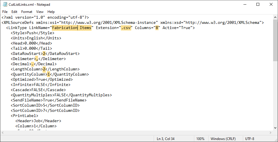
When we have only one set of <LinkType> & </LinkType> tags, we’re ready to start editing. I’ve highlighted the lines that I edited and/or verified in the following image…
Edit the Link Name which is the name of the Export configuration that will display in the left column of TigerLink.
Verify the Extension matches that of the export…CSV in this case.
As you recall, we have 8 columns of data in our export so use the Columns field configures this.
The DataRowStart tells TigerLink that the data starts on row 2 as our export has headers. Adjust as your export report requires.
Delimiter is set to a comma for a CSV but if your data has commas, you may need to use a different character.
Verify Decimal is set as required. Typically only different in some other countries.
LengthColumn tells TigerLink which column is the length TigerStop will use to drive the machine.
QuantityColumn tells TigerLink which column stores the quantity of parts.
At this point, we’ll ignore the other data as it’s easier to set via the TigerLink interface. Save your CutListLinks.xlm file and restart TigerLink.
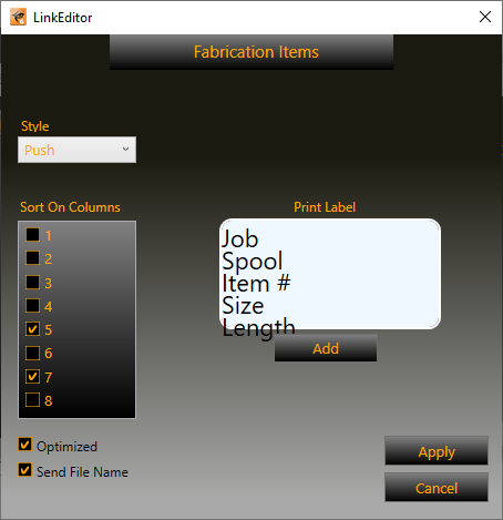
Step 4 – Configure Tigerlink via User Interface
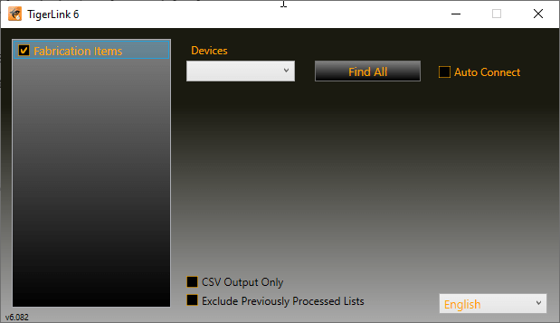
When you restart TigerLink, your version should look similar to the following…
The checkbox next to Fabrication Items tells TigerLink that this Export configuration is active and ready to be used. If you Right-Click on Fabrication Items and select EDIT, you get to the configuration user interface as shown below…
Here, we’ll want to do several things to finalize your configuration.
Put a check-mark next to Column entries 5 & 7. These columns hold the Size (Item description) and Material Name. This tells TigerLink that for this export, anytime there’s a new Size and/or material, it belongs in a separate file.
Unless you’re doing something unique, Style should be set to Push
Optimized tells TigerLink that the material will be optimized for best yield/utilization when nesting.
Send File Name is not required but can be used to display the file name on the TigerStop system.
Use the Add button to add data fields to your label. You can add a lot but TigerStop’s label system only works with up to 5 lines. Drag where you want and Right-Click to edit the header, font size and assign to a data column. Thje preview isn’t the most accurate as you can see. My data is off the display but does print properly. You can later go into the CutListLinks.xml file and get a little more fine control over the font size and placement in the <PrintLabel> & </PrintLabel> XML tags.
You’re now done configuring TigerLink and Fabrication. The only thing left is to process data from an export.
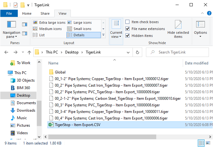
Step 5 – Process Fabrication Exports
To process data from an export, take a file with Fabrication piping in it and run the CSVEXPORT command. Once you;ve run the report you created earlier, look for the the CSV file and copy or move it to the TigerLink folder on the Desktop. Once the file is in that folder, TigerLink will process the file and break it into separate *.tiger files. One for each Material and Size if pipe.
These *.tiger files are what the TigerStop machine will use to cut your pipe.
If your CSV file is not processed into separate files, verify that the TigerLink software is running before you copy your CSV to the Desktop folder. Also make sure that the Fabrication Items entry in the TigerLink interface is selected to make sure it’s active.
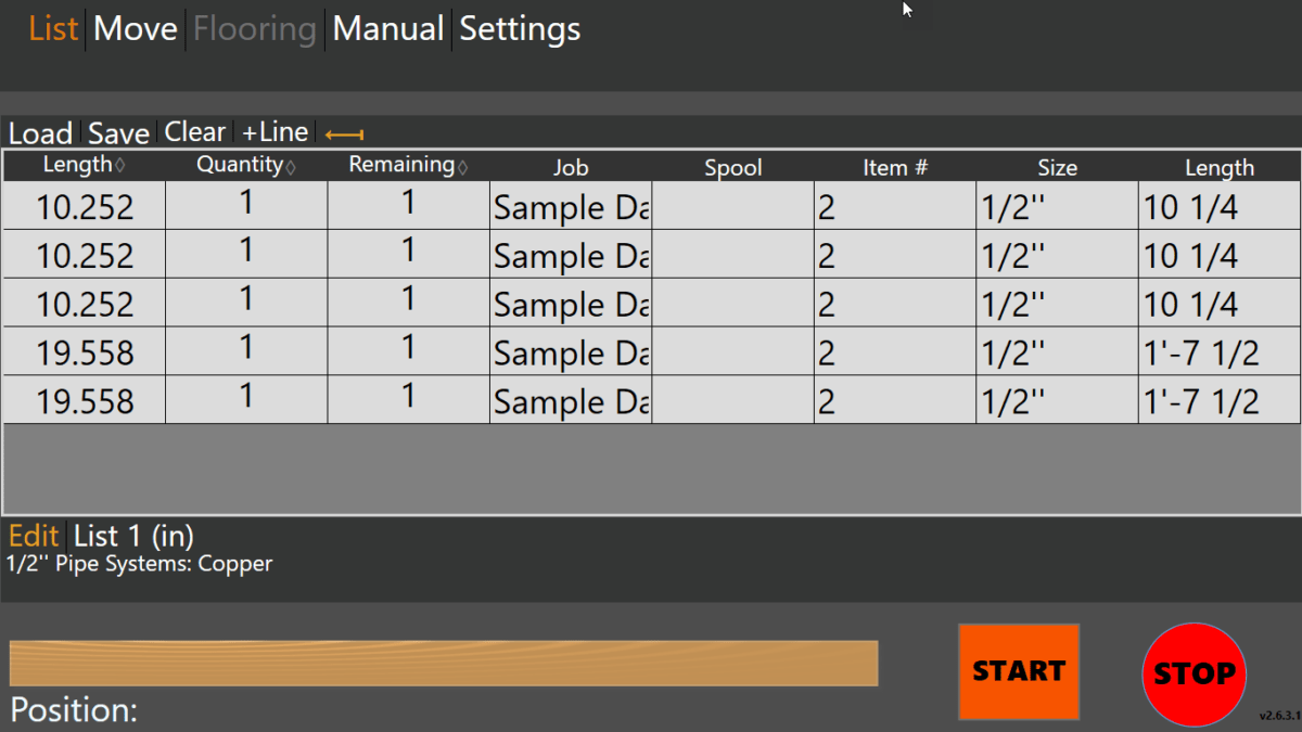
The following image shows how your file should look once opened in the TigerTouch interface…
Summary…
Ancillaries can be cut on a TigerStop in a similar way. Use the ANCILLARYEXPORT command to setup your ancillary exports. Using Ancillary Type and Names, you should be able to generate reports for your TigerStop to cut ancillaries.
Because filtering is limited, it may be a little harder to get a single export for all ancillaries. You may find it’s easier to create a report for each ancillary type. As long as all reports for Ancillaries have the same fields and number of columns, you should be able to just add a single “Fabrication Ancillaries” entry to the TightLink’s CutListLinks.XML file to process any of them.
For a copy of the CutListLinks.xml file and CSV Export report used in this example, you can download them from this file…
Warning: This is last part (4 of a 4) in a series on merging Autodesk Fabrication Databases. Autodesk Fabrication software is extremely powerful and flexible but that also makes it very fragile. Use the below guidance with caution. I highly recommend backing up your configuration before attempting anything I’ve recommended. It never hurts to have a firm grasp of how Autodesk Fabrication functions from an administrative perspective. Consider yourself warned!
Method 4: MERGEDB (CAMduct only)
This last method is very quick and powerful but only available in CAMduct. If you’re not a CAMduct user, simply download and install to perform this process while in the 30-day trail period.
This method doesn’t let you pick and choose individual database entries but you can pick certain database types and quickly merge all of them into a new configuration. Unlike prior methods were you typically started in the old Database to export an *.IOX / *.IEZ file or create a Proxy ITM first, in this process, you start with the database you want the items to be imported into.
In addition to make of the database entries Method 1 supported, this method also supports these additional entries.
Cutouts
Leads
Rates
Facings
Materials
Silencers
Hanger Specifications
Notches
Vanes
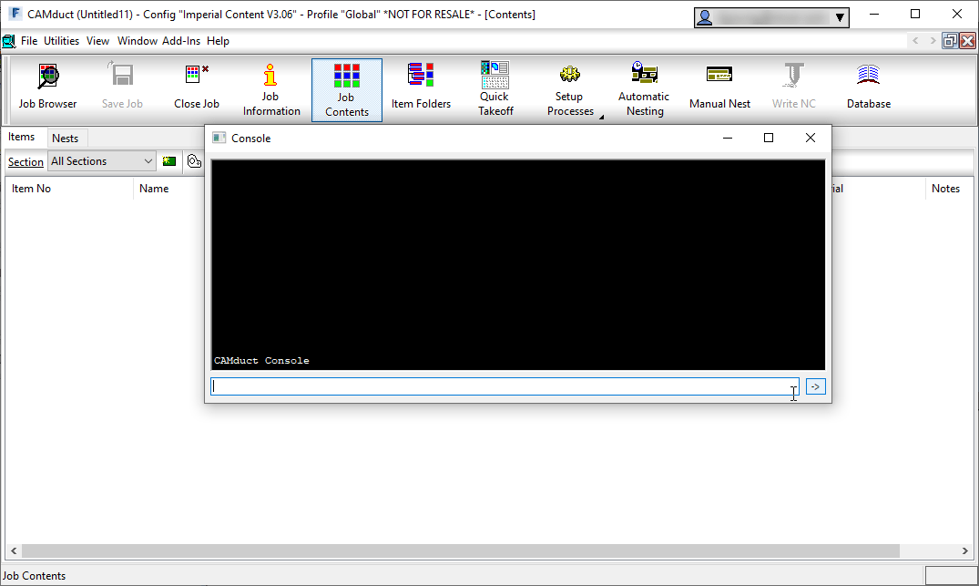
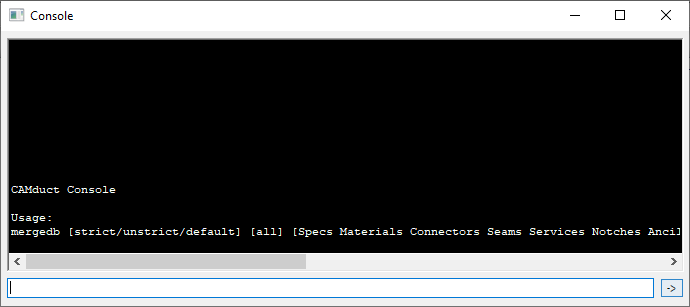
To use this method, start CAMduct and type CTRL-SHIFT-C to display the command window as shown below.
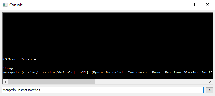
From the command window, type MERGEDB and press <Enter>. This doesn’t do anything other than tell you the data the command needs as shown below. The Strict/Unstrict options tell the merge process if it should only look at the name or the data to determine if it’s duplicate. If you choose strict and the items are already in your database, something as simple as 3 vs 4 digits after a decimal will cause a duplicate entry. In most cases, unstrict is all that’s required.
For this example, we’ll type MERGEDB UNSTRICT NOTCHES to import all the notches from one database to another as shown below.
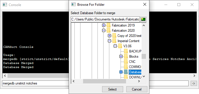
When you press enter, you’re prompted to select a folder. You should select the Database folder of the old database you want to merge into your current database.
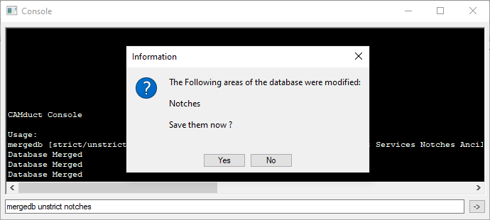
If new items are found, you’ll be notified and prompted if you want to save the changes or not.
Upon completion of the merge, you’ll need to go to those items in your database and make permanent any you intend to keep and remove those you didn’t want.
Pros: > Only way to import some database entry type. > Easiest way to merge the bulk of 2 database together. > Extremely fast and efficient. Cons: > Requires CAMduct. > Can not pick and choose database entries, only database types. > Requires post merge cleanup of deletion or making entries permanent
Warning: This is Part 3 of a 4 part series on merging Autodesk Fabrication Databases. Autodesk Fabrication software is extremely powerful and flexible but that also makes it very fragile. Use the below guidance with caution. I highly recommend backing up your configuration before attempting anything I’ve recommended. It never hurts to have a firm grasp of how Autodesk Fabrication functions from an administrative perspective. Consider yourself warned!
Method 3: Service Export/Import
This method is very similar to Method 2 above except that it works on a full service and all the items within it’s service template. If you have an existing service you want to post from one Database to another, this is a great method. Even if you just have a library of multiple ITM’s, it’s very common to create a transport service. That service holds those ITM’s and can be used as a means to get ITM’s from one database to another. Here are the steps.
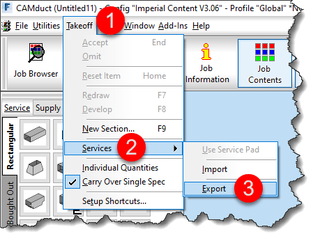
From CADmep, type EXPORTSYS at the command line or in ESTmep or CAMduct, while in the Takeoff screen, select Takeoff -> Services -> Export as shown below…
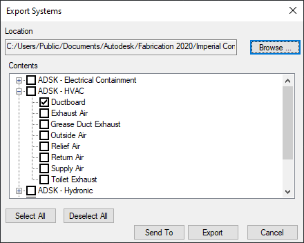
This displays the Export Systems dialog. Use the Browse button to select the location and name of the *.IEZ export file. Select the service(s) you wish to export and click the Export button.
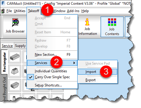
Importing is a similar process. Type IMPORTSYS from CADmep or from the Takeoff screen in ESTmep or CAMduct, select Takeoff -> Services -> Import as shown below…
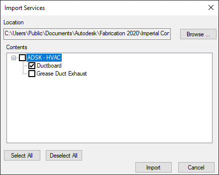
You are prompted to select an *.IEZ file for import. The file will be read and display all the services that were exported. Select those you want to import and click Import.
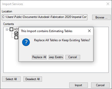
Because IEZ imports can contain a lot of data, it’s likely you may have a lot of duplicates. Upon import, you are prompted if you’d like to Import ALL or NEWER item. Select as appropriate for your situation as shown below.
If Estimating data is found, you are also prompted to Replace or Keep existing tables. Because the database you are importing to is likely your current desired database, I’d recommend to Keep existing tables and only Replace if you intend to bring over labor and cost data in the Import. Once again, choose the option that best suits your needs as shown below.
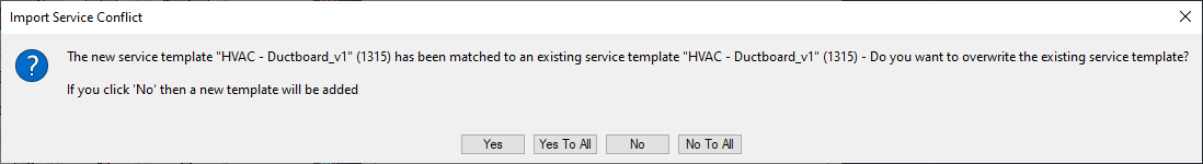
Like in Method 1 earlier, if the import finds a service or template it thinks is the same, it’ll prompt you how to proceed. I highly recommend NOT selecting the “….To All” options as it’s common for the database index to cause false matches and mislead you.
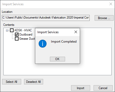
You are prompted once the import is complete. As with Method 2, if ITM’s imported through this process contain new database entries, you’ll need to find those and make them permanent in a similar way.
Pros: > Easiest way to import large numbers if ITM’s and their related database entries. > Easy way to import Services and Service Templates Cons: > Slowest of all process do to all the verification the Import process needs to do. > Can Import a lot more data than you intend. > Can not pick and choose individual database entries to import
Stay tuned for Method 4 in my next and last post in this series.
Warning: This is Part 2 of a 4 part series on merging Autodesk Fabrication Databases. Autodesk Fabrication software is extremely powerful and flexible but that also makes it very fragile. Use the below guidance with caution. I highly recommend backing up your configuration before attempting anything I’ve recommended. It never hurts to have a firm grasp of how Autodesk Fabrication functions from an administrative perspective. Consider yourself warned!
Method 2: ITM’s as Proxy
Another method of transferring data from one database to another is by using ITM’s. Simpy take an existing ITM or make a new one and set some of it’s properties to those you want to transfer. After you’ve completed this, copy the ITM to your desired database.
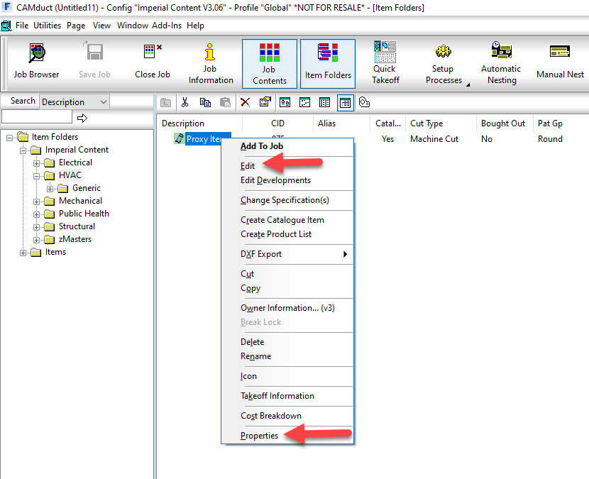
In your desired database, right-click on the newly copied ITM from the Folders view and select Edit or Properties as shown below.
Once the Edit Item or Item Properties dialogs are displayed, you can simply close them. The only purpose in calling them up was to force Fabrication to read all of their settings which in turn causes them to be created as Proxy entries in your database if they don’t already exist.
Once the database entries are in your new database, you’ll want to navigate to those database entries and make the proxy items permanent as shown below.
Pros: > Every property an ITM uses is supported. > Dependent database entries supported (e.g. Fixings on a Support) Cons: > Can bring in more properties than you want which need to be cleaned. > Time consuming for large property sets as multiple ITM’s required. > Proxy items must be manually made permanent afterward
If you use Revit’s Fabrication Parts, CADmep or any of the other Autodesk Fabrication products like ESTmep or CAMduct, you use ITM content. ITM files can be tricky and time consuming to build. If you don’t want to tackle it yourself or just done have time, I recommend Virtual Building Supply (https://itembuilders.com).
There are other companies that will build ITM content for you but their quality varies. Nibco as an example, is two companies removed from the firm that produces their content. As that firm has had some questionable business practices, I won’t get into detail other than to say I can tell just by looking at an ITM if they created it. If they did, I won’t use it.
There’s a few Autrodesk resellers as well who will build ITM content slightly cheaper but don’t put the quality or extra data associated with it into their work.
Virtual Building Supply on the other hand is run and operated by industry insiders. They’ve installed pipe. They’ve managed Autodesk Fabrication databases. They know their stuff.
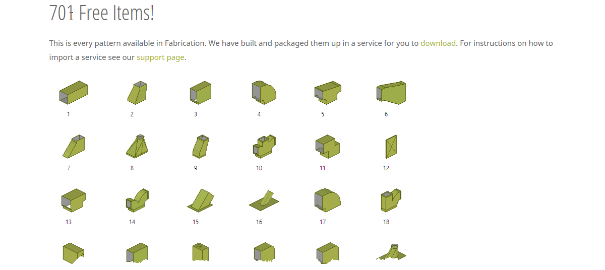
If you browse to their downloads page, the have a few things you might be interested in…
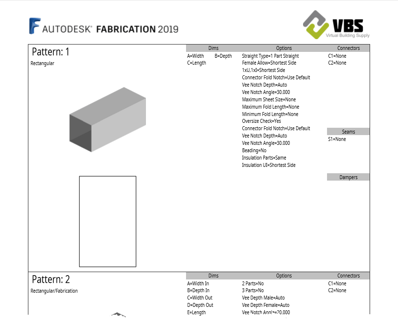
PDF Catalog of Fabrication Patterns
IEZ Service Import File w/All Default Pattern Numbers
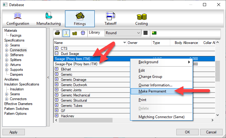
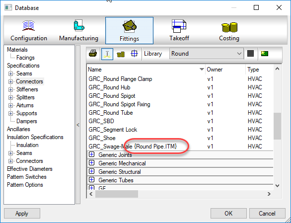
Don’t leave proxy items in your fabrication database.
You’ll notice these as they appear with curly brackets { } around a piece of text like an ITM name or DWG name.
These proxy objects can show up many places. Services, Service Templates, Materials, Connectors, Seams, etc. They occur when an ITM or drawing containing ITM’s references a database entry that no longer exists in your Fabrication configuration. As an example, if you delete a connector from your database, let’s say “Copper Cup” then later add an ITM to your drawing that contains a reference to that connector, it gets added back to your configuration and displays the ITM name in the curly brackets.
If there’s bracketed items in your database they should either be made permanent or deleted. If deleted, they may keep coming back. If you truly want them gone, you need to find the objects bringing them back and update them to the new item in your database configuration that they should point to.
A properly managed Fabrication database configuration should have everything configured properly. Items with curly brackets are an indication that things are not configured properly.
Future posts will explain various techniques to help identify where these bracketed items come from as well as how to correct them efficiently.