Shop Math 101: 1/100″ = 1/4″
Does your fabrication shop lack confidence in your drafting/detailing department?
Have you struggled to get buy-in when trying to roll out new processes, technology or deliverables?
Did you wonder why? More importantly, do you KNOW why?
Getting to the Root of Trust Issues
My entire career spanning manufacturing to construction, fabrication shops have had trouble trusting the information they’re given. And there’s good reason. It takes time to master a domain and learn the work. And production staff are busy building and fabricating. They don’t have time to run into the office every time something is wrong. As a result, office staff take longer to train and often persist with producing lower quality work.
But there’s also a lot of reasons that are not good. Downright bad in fact because they’re simple to resolve. Things you’re NOT doing wrong but are causing problems. These trust issues are easily corrected if they’re understood properly. One such issue is fabrication tolerances that I categorize as Shop Math.
The Dynamic Between Tolerance and Rounding
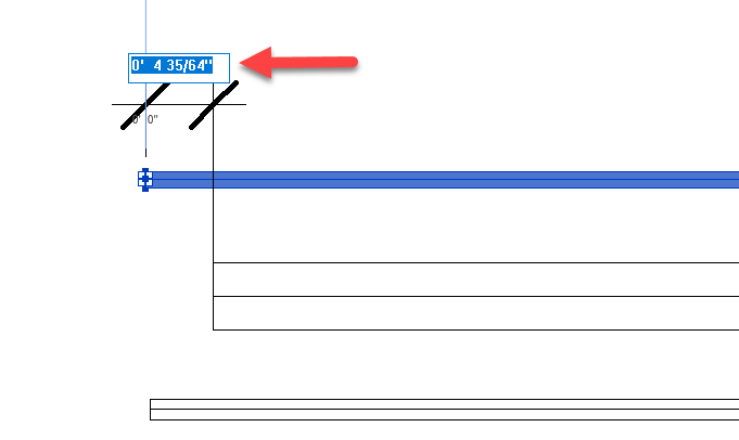
I’ve had trouble explaining this verbally so I figured a more graphic (yet generic) representation would be in order. In basic terms, you need to use a rounding factor 1/2 the amount of your fabrication tolerance to achieve the desired result. As the title of this post suggests, a value of 1/100″ of an inch, can result in a deviation of 1/4″. That’s real Shop Math in practice.
My example uses both fractional inch and decimal to more clearly illustrate the point. You don’t want to get me started in why everyone should use decimal, that’s another post. But decimal also has the same dynamic, it’s just less hidden and more easily fixed. You get a lot less pushback in a shop by adding an extra decimal than by changing the denominator of a fraction to a number the shop says they don’t fabricate to.
Let’s take the following example..,
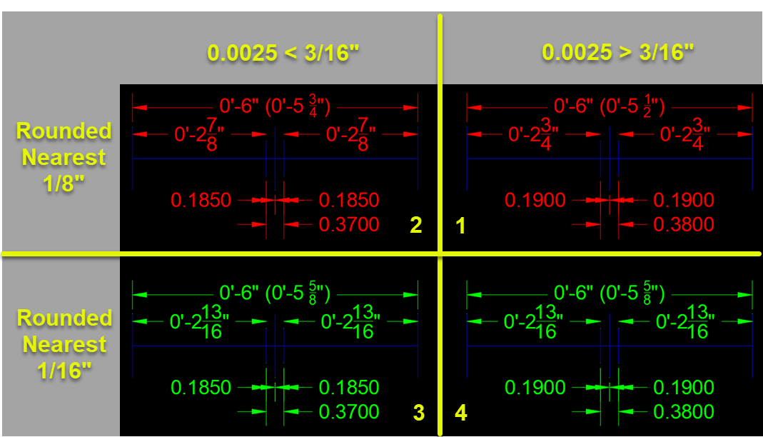
In this example, lets assume our tolerance is 1/8″ (construction field tolerances, that’s fairly common).
The TOP RED dimensions are all ROUNDED to the nearest 1/8″ to match our target Tolerance. A fairly common practice. The BOTTOM GREEN dimensions are all ROUNDED to the nearest 1/16″ which is half our target Tolerance.
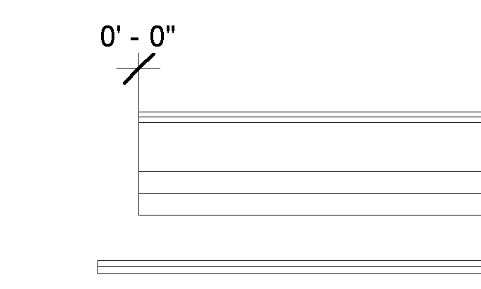
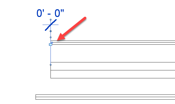
Each graphic shows a line 6″ long. Half that is 3″. We’re going to make a gap and dimension from each end to that gap. Maybe it’s a weld joint in pipe or perhaps a mortar joint in concrete block. Doesn’t matter what to illustrate the problem.
For the graphics on the LEFT (Quadrants 2 & 3), the gap is just shy of 3/16″ of each side of middle to forced the dimension to round UP. For the graphics on the RIGHT (Quadrants 1 & 4), our gap just heavy of 3/16″ of middle to force the dimensions to round DOWN.
Rounding = Tolerance = Confusion = Mistrust
Let’s focus on the TOP RED in the following illustration…
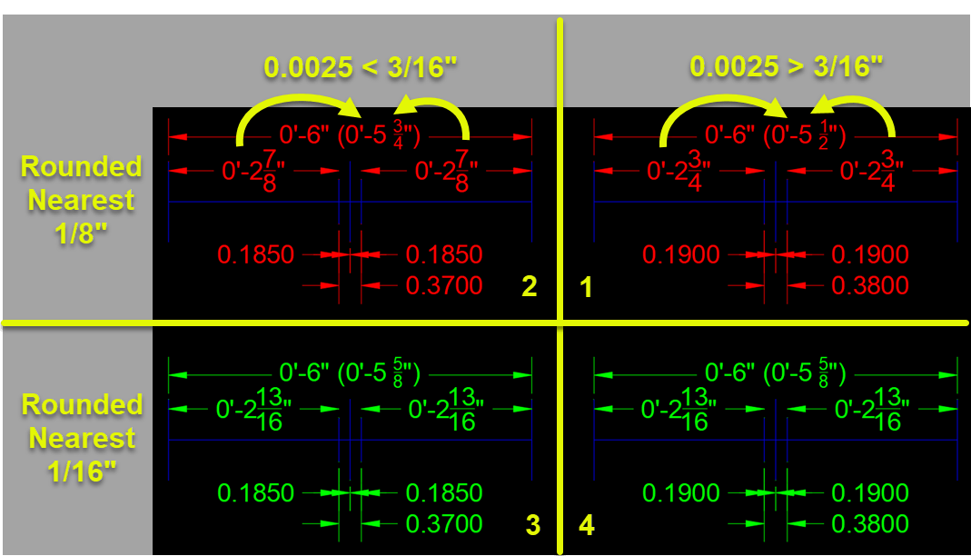
If you take the two parts and add them, they vary by 1/4″. Adding 3/8″ (our rounded gap size) to either of them does not equal 6″ either.
Quadrant 1: 2 3/4″ + 2 3/4″ + 3/8″ = 5 7/8″
Quadrant 2: 2 7/8″ + 2 7/8″ + 3/8″ = 6 1/8“
Between these 2 examples, a mere 1/100″ difference in our gap results in a 1/4″ difference and neither adds up to the 6″ of the total length. This is a 1/4″ TOLERANCE because we set ROUNDING to 1/8″ to match our fabrication accuracy.
If you ever wondered why your shop doesn’t trust your drafting/detailing, this is one reason. The Shop Math just doesn’t add up. They see the sum doesn’t add up to the whole and leads them to question the accuracy of your drawing and your staff.
Rounding = 1/2 Tolerance = Trust
Now lets focus on the BOTTOM GREEN portion of our illustration…
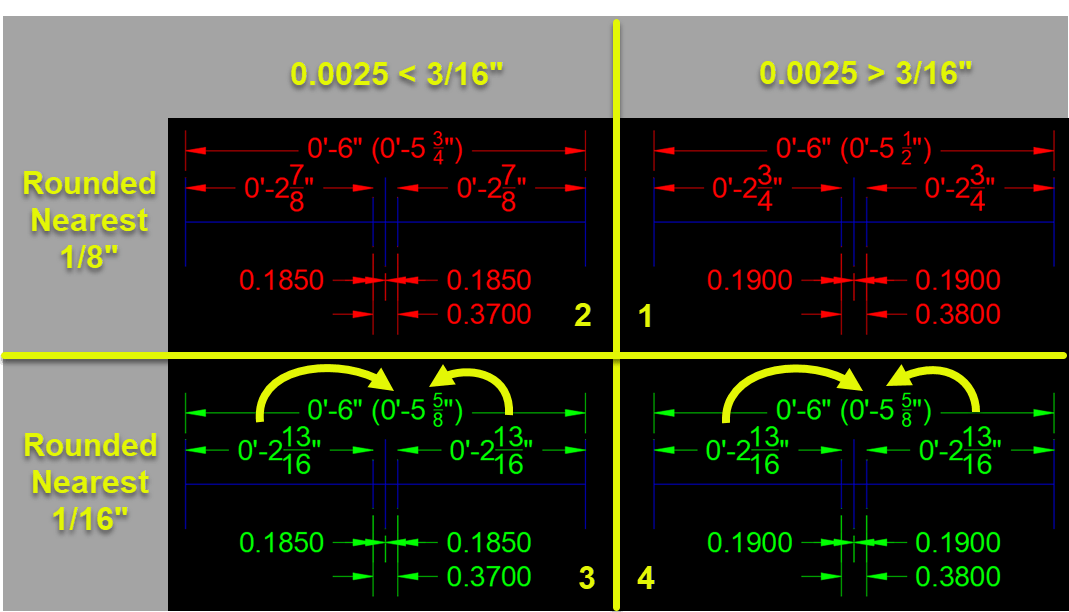
Between the left and right (Quadrants 3 & 4) we’re still making the gap just shy and just heavy of 3/16″ from the center. As you recall, we said our fabrication tolerance target was 1/8″ but here, the dimensions are ROUNDED to 1/16″. This is HALF of our target fabrication Tolerance.
Here, it doesn’t matter of the dimensions round UP or DOWN due to the slight variation in the gap, the dimension are the same. Furthermore, if you add the parts, you get 6″.
Quadrant 3: 2 13/16″ + 2 13/16″ + 3/8″ = 6″
Quadrant 4: 2 13/16″ + 2 13/16″ + 3/8″ = 6″
Same Geometry – Different Clarity
As you can see, we had different results between rounding UP and DOWN when our ROUNDING value equals the Tolerance we’re trying to achieve. When we round to HALF the Tolerance, those small variations are masked and all our numbers add up.
So if you’re dimensioning for the shop, it’s important to realize this little change can mean questioning or trusting your data and staff. Additionally, if you take the time on the shop floor to explain WHY they see these differences, they quickly realize that the information that leads them to question the data (and your people), is also the very same data that’s most likely to be wrong. What IS accurate and didn’t change, is the geometry itself. This is an extremely critical point to highlight if you’re trying to get your shop to use automation and drive machine tools from CAD/BIM geometry.
The model/geometry, is the MOST right data we have. It’s just not human readable and what we provide as human readable is prone to errors such as these. This is one reason you’re seeing terms like “Model Based Enterprise” starting to float around in the Manufacturing space. It’s also a reason you’re seeing more shop go paperless, eliminating dimensions when possible by leveraging automation.
These efforts can be challenging and often require a leap of faith. But if everybody understands dynamics like this, it can be extremely helpful in moving all of your staff to more digital workflows. Because they trust the geometry and you eliminate what’s confusing them.