AutoCAD was famous for it’s command line. It was easy to move items and type locations, distances or coordinates. Revit isn’t quite as intuitive for those coming from AutoCAD.
There’s a lot of reasons you need more control of Fabrication Parts in Revit. You may want to align the ends of pipe for a rack. Or perhaps you want to control the spacing between pipes in a run of parallel pipes.
At first it appears like the best you can do is drag items close. Eyeball them up so to speak. The traditional methods used in AutoCAD just won’t work. Methods like drawing construction geometry and using point filter and/or object snaps.
You can precisely control placement and location when moving to Revit from CADmep. In Revit, you simply place dimensions and edit them. Seems easy enough but there’s a couple nuances that can leave users frustrated. We’ll cover how to do this below.
Adding Dimensions in Revit
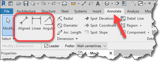
You can use the Annotate tab on the Ribbon in Revit. You’ll use the Linear, Aligned and Angular dimensions the most.
When you place a dimension between parts in Revit, the obvious thing would be to double-click the dimension to edit it. You’ve likely seen the following dialog…
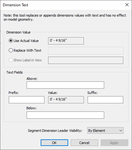
If you see this dialog, you’re on the wrong path. This is not where you’d edit a dimension to control part placement. For controlling parts with dimensions in Revit, you actually select one of the parts you dimensioned.
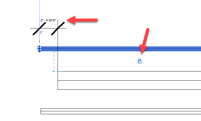
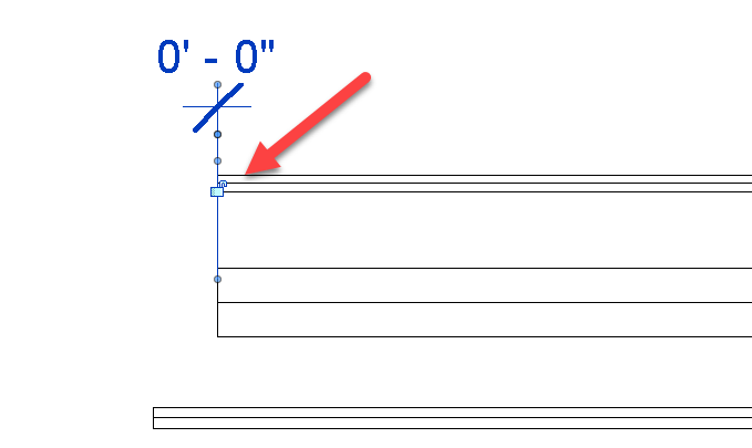
The following image shows a Fabrication Part selected. But there’s still a problem. If the dimension text is black, you can not edit it. This is because one of the parts are over constrained. If you find a Lock icon on one of the parts, try unlocking it.
After unlocking the part, you may need to deselect and re-select the part for the dimension text to be editable. In the following image, you’ll see the dimension text is now Blue.
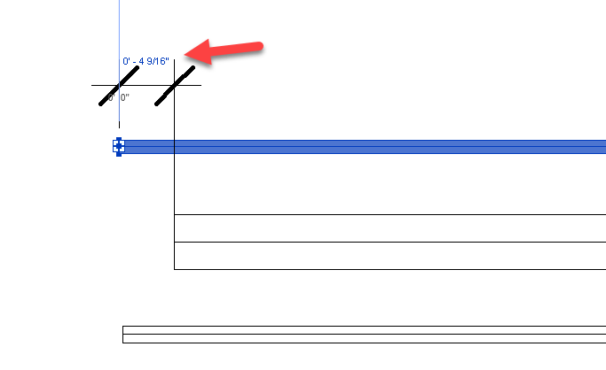
With the dimension text Blue, you can now click on the text to edit it as shown in the following image.
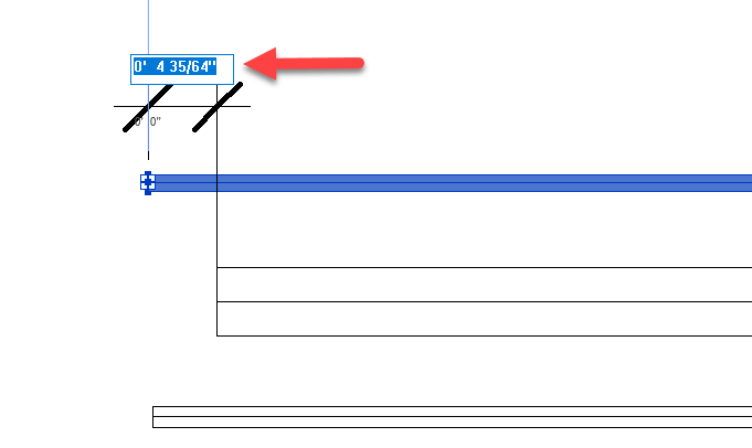
With the edit box for the dimension text activated, simply type the desired value and press <Enter> or click out of the edit box.
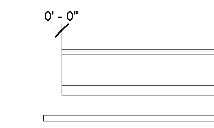
You’ll see the part move to the dimension you entered. The key to determining which part moves when editing a dimension is based on the part you select. If you just wanted to align the parts, you can delete the dimension afterward. On the other hand, if you want to maintain that relationship, highlight the dimension. You’ll see a unlocked Lock icon as shown in the below image.
If you click to Lock the icon, this relationship between parts will be maintained going forward.
The below video shows three pipes modeled with various end lengths. We’re using dimensions to align the ends of the pipe. We also delete the dimensions afterward. Moving one of the pipe ends later will not move the ends of the other.
Pipe spacing is set using dimensions just like before only this time, the dimensions are retained and the lock icon locked When one pipe later moves, the other moves to maintain the spacing.