Quick little Stratus tip. This on for headers on your Dashboards. A normal dashboard doesn’t have the ability to customize the header. However, being Stratus is a web based application, you can inject some simple HTML tags to perform some limited modifications.
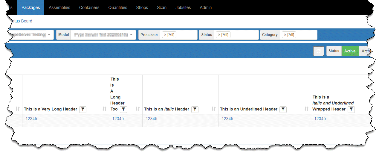
Take a look at the following headers….
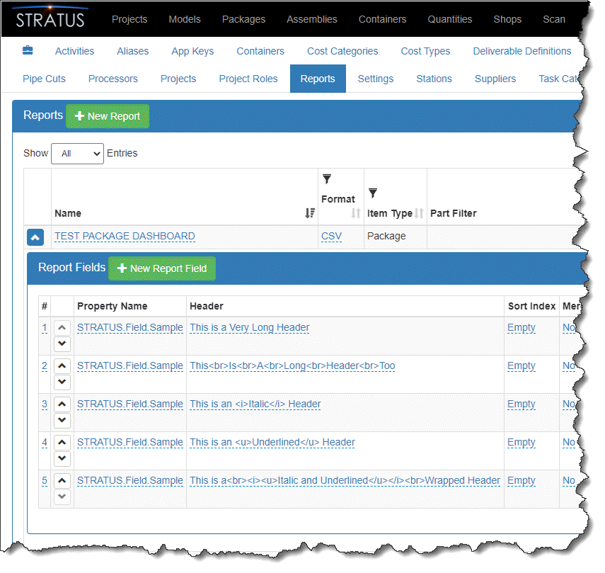
These headers are a result of inserting some very simple HTML tags. Here’s a look at the Report configuration for these header modifications…
Here’s an explanation of these HTML Tags…
HTML Tag(s)
Description
Usage
<br>
Break Line / Carriage Return
Place between text to create a new line
<i> </i>
Italics
Text placed between these tags will be italic
<u> </u>
Underline
Text placed between these tags will be underlined
A few things to note…
You can nest <i>Italics</i> and <u>underline</u> to transform text to <i><u>both</u></i>.
More complex HTML tags don’t work, there’s just too many special characters.
HTML tags may (will) show in other places like in the output of CSV files and/or other types of reports.
The usage of HTML tags in your Dashboard headers is likely not supported. If you find any errors within Stratus on pages that you’ve used these, you may want to remove them to verify the special characters aren’t the cause of your issues.
Autodesk recently made a policy change to its prior version usage policy. Previously Autodesk’s policy was to allow customers current on subscription or maintenance to run the current release and the prior 3 versions. However this policy recently changed on November 2, 2020 to allow 5 prior versions.
One important thing to note however, is this change does NOT affect support. Autodesk Support will only help you with the 3 prior versions.
Because it was likely what customers wanted, it sounds like a good change . But it’s really bad news for the industry. The intent was to help customers who were not able to upgrade for some reason. But this change wasn’t needed to serve that purpose. Autodesk would (and did) grant exceptions from the “3 prior version” terms on an as-need basis. Whenever you needed an exception, just ask your reseller. They could then request an exception from your regional Autodesk rep.
Unintended Consequences
This change is bad because it’s one more reason customers can use to not upgrade. That’s not the purpose of the policy but it will be the result. Because most customers are now on subscription, the policy really doesn’t affect Autodesk’s revenue. As such, it was really not hard for them to do. You still have to be on a subscription plan.
When customer’s don’t upgrade, they don’t benefit from new features and functionality. In the case of MEP, Fabrication Parts are still relatively new to Revit. This means there are significant functionality improvements in newer versions. But because there’s not as many improvements for Architects, they may not upgrade. And because they lead on the project, MEP has no choice but to use the version the project team is on. This easily leads to a significant lost productivity and added cost for MEP contractors.
This is my 4th and last article on Digital Transformation for the average contractor. The whole point of this series was to help companies understand that they don’t need to know what the future holds to prepare for it. If you missed them, the other 3 articles can be found here…
In this article, we’ll look at an action plan. By using this plan, you can help focus your efforts.
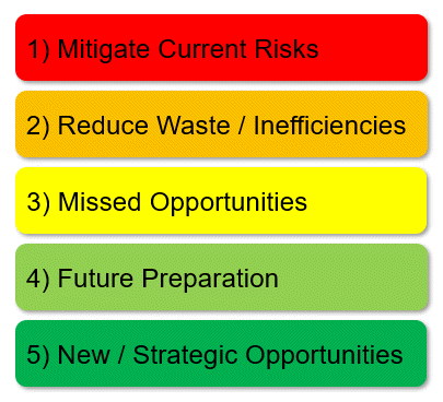
A 5 Step Action Plan
It can help to prioritize with any effort. Because there’s a lot to do, it’s easy to get lost in all the work. Your action plan may look different and it should be if your needs are different. However, these 5 steps are a good starting point.
Step 1 – Mitigate Current Risks
You might have existing risks because of prior actions. You can only mitigating these risks if you identify them. Review what you’re currently doing because that’s likely where they are. However some risks may be due to what you’re not doing. Here’s some ideas to get you thinking….
Is your data backed up? Not just server data but cloud systems, machine tools, etc.
Are you managing user accounts in all your technology systems?
Do your advanced or complex configurations have documentation?
Is your data accurate (BIM Content, Models, Standards, etc.)?
Are users trained in proper processes and technology usage?
Do all your technologies have an “owner” or responsible party?
Is Staff cross trained or does your technology and processes rely on only one person?
Who is maintaining your standards? Is there even governance around them?
Are there things critical to your organization controlled by others outside your organization?
What things have “Single points of failure”?
Step 2 – Reduce Waste and Inefficiencies (Create Value)
Your next step is really something you likely do already. Reducing waste and inefficiency. However it’s a good idea to revisit occasionally. After you’ve documented your workflow, developed a new workflow or changed your technology. It’s good to revisit how these things impact your efficiency and drive value. Some general thoughts that can apply to most company…
Are users aware of how your technology should be used (training)?
Do you have under utilized or misused technology or processes?
Duplicate technology for the same purpose?
Are there things you do that are easily outsourced?
What can be automated but isn’t?
Do new cloud workflows represent what should happen or did you simply move your existing processes into the cloud?
Are your computers or hardware setup consistently, maintained proactively or built with automated processes?
Step 3 – Missed Opportunities
One area people don’t think about enough is missed opportunities. You’re always watching costs vs benefits. Results of doing things. But what’s the cost of not doing something? What’s the cost of missed opportunities? These could come in many forms. It’s best to build your own list but here’s a few examples…
Leverage knowledge from existing staff
Free or joint marketing from vendors or customers
Missed value you could sell if you were leading edge with technology
R&D opportunities with technology vendors
Existing competencies not marketed properly
Step 4 – Prepare for the Future
This step is really what Part 2 and Part 3 of my series was about. These are things you can do now, despite an unknown future. There’s a lot you can do right now that sets you up for success down the road. However you don’t need to wait until the first three steps are done. You can start chipping away at these now. They just shouldn’t be your primary focus until Steps 1 through 3 are well underway. Here’s a few ideas, feel free to add your own…
Document existing processes
Develop ideal workflows
Start building missing competencies in staff and departments
Restructuring existing technology stacks
Capture wisdom of staff nearing retirement
Reverse mentor older staff by tech savvy younger generation
Step 5 – New Strategic Opportunities
This step is the hardest to provide guidance on. It really depends where your company sees itself going. The skills they have can help differentiate itself in the market place from others.
Here’s were an ear to the ground can be helpful. Trying to anticipate what trends in construction may be fads vs long lasting or even transformational. How can you leverage them? How can you change your business to remain relevant? Regardless of the future, if you’ve followed all the other guidance, you should be able to easily adapt when these trends emerge.
Will you be a manufacturer in an “Industrialized Construction” economy?
Do you have staff capable of developing prefabrication or modularization strategies?
Are you able to be an efficient supply chain provider?
Can you help your customers with smart building technology?
Will Machine Learning or Artificial Intelligence render you obsolete or is it simply a tool you use?
Who are the new players in the construction economy and is there value you can bring to them?
How can you capitalize on the struggles of your competition?
Summary
Aside from here in Step 5, everything in this series of posts are things you can start doing right now. They’re things that don’t require a prognosticator’s view of the future. Yet they’re all things that will help you be more agile and able to adapt when trends or disruption comes knocking.
You don’t have to worry about the future to prepare for it. There’s enough to do right now that you can stop worrying. More than likely, at some point you’ll take notice and see you’re living the future. The actions and choices you’ve used to prepare you allowed you to tackle the future without even realizing it.
Make smart choices. Stay busy. Stay Relevant. You can eat the future one small bite at a time.
I discussed the problem and overall objective of digital transformation in construction in Part 1. In Part 2 I outlined four activities you could take right now. Activities that cost nothing more than time. These activities can really help inform you. Guiding where you should start working when aligning your technology stack.
There’s a lot of things you can do to better align your technology. While there’s no magic formula there are a few categories these activities fall under.
In many cases, you might be removing technology from your portfolio. Maybe it’s obsolete or ineffective. Whether your processes have changed or the technology didn’t stay mature it’s best to remove things that are no longer needed or don’t provide the value you were looking for.
It could also be that there’s overlap in solutions. Does more than one product serve the same purpose? You typically don’t want more than one solution for the same problem. There can always be exceptions. But you should have a very good reason if you have duplicate technology.
In many cases, you already have good tech in place. However you may not be using it correctly or to it’s potential. This is often a result of someone solving a specific problem and buying a product to address it. This can result in technology you haven’t fully implemented or is implemented poorly.
This doesn’t mean the solution is bad or that the effort was bad. But it can be helpful to revisit. Is there more value you can leverage? More of your processes and workflows covered? Can you use the product differently to achieve a greater purpose?
When you realign existing tech, it often just takes time. Time to relook at the factors that led to it’s use. Relook at how things have changed. Changes in your process as well as how the product may have matured since first selected.
Can you change your process to better accommodate the product’s value proposition? Can you change how you use the product to better serve your needs? Here’s another case where it only takes time if you have a good tech savvy person in house.
It might also be wise to leverage a vendor or consultant to help. You might also consider leveraging vendors for training. They have experience with other firms using their tools. With their knowledge, they can often can point out use cases you might not have thought of.
The other cost during realignment of technology is licensing. If you’ve under or miss utilized technology, fixing this problem may result in additional use. This translates to additional licensing costs for you. This isn’t bad. It’s good. The whole point is to gain value and productivity. Both of those things should be worth paying for. If not, it’s a sign you’re using the wrong tool.
When it comes to new technology, the number of choices can be overwhelming. You may not know what the future holds. And every vendor claims they’ll lead you there.
The fact is, you don’t need to be a prognosticator to choose good technology. There’s a number of basic concepts and criteria you can use when evaluating technology. Concepts that help you make better choices regardless of what the future holds.
When I look at technology, there’s a number of questions I ask myself about a potential solution. Here’s a partial list of things take into consideration. There is no right or wrong answer. They won’t all be true. But you can get an idea if you have a good solution or not based on these and other factors. When using these criteria, your choice will likely be better suited to the future even if it is unknow. Make your own list or add to this one….
Is it cloud based or enabled? Most things are migrating to the cloud. If it’s an on premises only solution, it’s not aligned with the future as well as a Cloud based solution.
Does it reduce or eliminate paper? Anything that reduces or eliminates paper will help reduce static obsolete data.
Will it reduce or eliminate data files? Much like paper, data files are typically copies of the real data in a system. Think of a PDF, it’s really electronic paper. Give preference to anything that gives you real time access to data without needing “files”.
Is duplication of data reduced or eliminated? Data duplication is never good. It requires extra effort to keep in sync or find out why it’s different. Find solutions that reduce data duplication in your environment.
Will it simplify or eliminate processes? If it makes things simpler, there’s less waste. Less training. Less things to go wrong.
Does it simplify IT infrastructure? Your IT infrastructure can often be impacted by technology. Solutions that simplify your infrastructure can often be an added benefit.
Is it Model based? Can the solution leverage your BIM or CAD models? Not just export data from them or convert them but use them directly to provide value? A Model Based enterprise is what you should be striving for.
Can you integrate it with other solutions? If you can’t integrate with anything else, you’re boxed in. Even if you don’t have anything currently to integrate with, you typically want that ability later should you need it.
Does it have an API (Application Programming Interface) Without an API, you can’t automate anything like data mining or integrating with other solutions. Even if you don’t have a programmer, you may want to use one later. Don’t limit your future options without a good reason.
If it doesn’t meet some of your criteria, does it get you closer? Sometimes we just can’t get everything we want. It might be too much of a change or maybe it’s just not available. But can you get closer? Don’t over look incremental improvements.
Digital twin? Does the solution get you closer to having a digital replica of your product, facility and/or process?
Has manufacturing used a similar solution? Manufacturing has led trends seen in construction by two or three decades. BIM in AEC is similar to PLM (Product Lifecycle Management) in Manufacturing. 3d Parametric Modeling? LEAN? Model Based Enterprise? Prefabrication and Modular construction use similar concepts as DfM, DfA or DfMA in manufacturing that helped re-shore a lot of work that was once offshored.
Have other industries used similar solutions or concepts? Shipbuilding has transformed to use modular. Healthcare leveraged a lot of Toyota’s Lean concepts. GIS uses CAD data linked to external data sets. A lot can be learned from watching others.
Is time eliminated from your process? Any solution should put time back in someone’s day or reduce lead times.
Does it build in quality? If using the solution, will it help mistake proof your processes?
Will the solution require a dedicated administrator? Many solutions sound good on the surface but require a lot of administrative overhead. Verify the cost of administration when looking at any technology.
Is data better organized? Will using the solution help better organize your data and information? Data is of no value if others can’t find what they need.
Can it leverage or use existing data? You have a lot of data already. Can it leverage or use what you already have and provide more value to an existing data asset?
Does it turn data into information? Data is worthless. Information is priceless. Make sure any solution provides information, not just data.
What % of existing data/systems is being used? How much of what the solution offers is actually going to be used or helpful? Features don’t provide value if they’re not going to be used or helpful.
Is the data in system(s) or file(s)? Data that resides in a “system” or database is typically more flexible than in a “file”. File based data typically requires additional management and processes. This makes them prone to user errors.
Can data be captured as a natural byproduct of using the product or does it require a separate work activity? If it takes you a lot of time to log, capture or report on data, that’s a separate work activity. Any system that makes you feel like you need a separate cost code to account for your time just to use it, is likely not a good solution.
Does using the system help standardize data? Standardized data typically yields more value with higher reliability and often eliminates a lot of human error.
Will it help with “Aggregation of marginal gains”? Sometimes a solution’s value isn’t the “one big thing” it does rather that it does or helps facilitate a lot of small incremental improvements.
Can you get a return in 1-2 years? Don’t worry about predicting the future. Tech moves fast. Be cautious of any solution claiming they’re the “Future”.
Is it the lesser of 2 evils? Never a decision anyone likes to make but sometimes a problem is big enough and the benefits in other areas are significant enough that what you do compromise on is the lesser of two evils.
Does it get you closer to your vision? Sometimes you can’t implement the solution you want. It may not exist or it’s just too big a change for your organization to swallow. Don’t dismiss smaller changes over time. Nobody said it’s a permanent solution.
Are Licensing terms flexible? Paying the same licensing cost for part time users as full time is wasteful. Likewise, solutions that want a percentage of revenue can be costly. You can’t always choose licensing terms but they’re often negotiable to a point. Verify the percentage of revenue is revenue from processes the solution addresses. Try to limit licensing costs early on in the implementation…you’re not using the full solution on day one.
Can you replace the solution easily in the future? Nothing is forever. How easily will you be able to swap the solution for another should your needs change?
Your list of things to consider when choosing technology solutions can and should vary. The point is, we don’t have to be able to predict the future with laser accuracy to select good technology. Use common sense concepts and principals and you’ll be well positioned for an unknown future.
In Part 4 (my last in the series), I’ll cover some aspects and approaches to prioritization.
In my last article, I showed a high level overview of what you’re trying to achieve. Digital transformation in construction is really about eliminating data silos and data handoffs. Because you now have a clear vision of what you want to happen, you’re ready to start putting your plan in place.
Looking for solutions at this point might be tempting. I know I’m always eager to jump in and start problem solving. But let’s hold off on that for now. Put a pin in it and we’ll get to that later.
4 Actions You Can Take Immediately
Before we introduce any new technology solutions, there’s actions you can take right now. You don’t need to write a check or create a budget. Because the only cost is your time and that of your coworkers.
Because they’re not required, my observation is that most companies don’t perform these steps. You’ve likely heard the saying “Time is money” countless times. But in my career I’ve noticed that you can typically waste 10x more money than you spend before anyone ever notices.
Because these steps only take time, there’s really no reason you can’t do them. It’s highly recommended that you do. If for no other reason, the end result will be a good communication and sales tool. It’ll help you move your initiatives forward with those that aren’t as tech savvy and don’t see the path to digital transformation.
Action 1: Workflow and Process Mapping
The first action you can take is to document your existing workflows and processes. By “your”, I really mean the workflows and processes of your company. Many refer to this process as “Value Stream Mapping”. If you’re not familiar with the “Lean” jargon don’t get caught up in the semantics. You’re really just trying to capture and diagram what really happens.
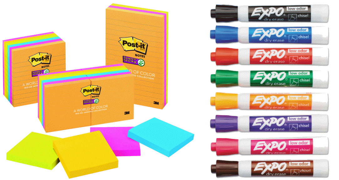
To do this, meet with various groups of users separately. You don’t need a whole department. Choose a diversity of people that will give you the broadest possible honest feedback. To help your groups easily visualize what they’re communicating, write on a whiteboard or use Post-It notes on a wall.
Tools for Documenting Existing Workflow
Ask simple questions. Pretend you don’t know anything about the workflow or processes.
What do you need to start you work?
Who do you get information from to do your job?
How do you receive this information?
Are you ever missing information?
Where do you get answers to your questions?
What are your deliverables?
Who do you give them to?
…etc…
The idea is to capture all the variation in a group’s workflow. Different ways information is obtained or delivered. Differences in who you get information from or give it to. Variations in data types or quality.
When you document these workflows, take note of value added activities as well as waste. When you’ve documented all the various groups, you can start piecing together workflows of different groups. You’ll likely start seeing some common themes of waste, value or workflows.
Action 2 – Data Documentation
The second action is documenting the lifecycle of your data. It might make sense to actually start this as part of your workflow mapping earlier. As long as you have people together, might just as well start asking them about their data too. That’s because workflow mapping can really inform you about a lot of the data that’s used.
This documentation is sometimes referred to as “Cardinality”. Again, there’s no need to get caught up in semantics or official definitions of the process. You’re essentially just documenting everything you can about you data.
What data “Could” you use if it was easily available?
Who can create the data?
Is the data static or does it change?
Who can edit the data?
What data do you use?
Who only views the data?
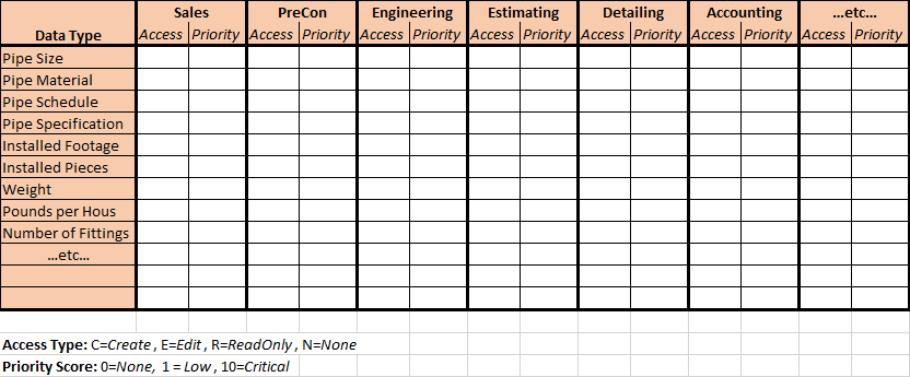
As you document the data, take note of the user type. Engineer, Detailer, Project Manager, Shop, etc. For each type of user, note if they create, edit or use any particular piece of data. Do they need it or could they merely use it? How important is the data to that group? As an example, engineering data is obviously more important to an Engineer, Fabrication data to the shop staff and so on.
Example of a Data Ranking Matrix
A few suggestions while gathering this information…
Don’t call it “BIM Data”. Just call it “Data” or people will automatically limit their feedback to their personal definition of BIM. I received more input when I simply referred to “Project Information” or “Data”
When you meet with more users, your list will grow. You might want to take a second round of questions after your initial list grows.
Take note of data importance to different user types…Critical….Helpful…Nice to Have…etc.
Action 3 – Develop Workflow & Process
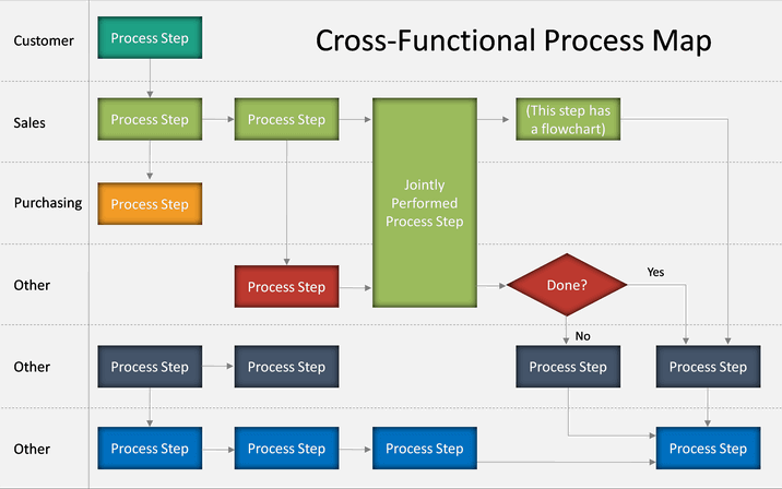
Another important step is to map out your ideal workflow(s). When doing this, it’s a high level exercise, you’re not documenting picks and clicks. Most commonly you see this done using a diagram with swim lanes. You might also end up documenting several workflows. Workflow differences between contract types (Design-Build vs Hard Bid) or customer types would be common. You’ll want to start with the workflow that most closely aligns with your work.
Swim Lane Diagram Example
In your workflow and process document, you should be highlighting information flow. What information or decisions are made, where and when they are made, and where that flows.
Your ideal workflow should be more simplified than the process map you created earlier. It’ll be hard to get out of your head preconceived notions. But try to just focus on the data so your ideal workflow is not designed around technology. Try to remember…People….Process….Technology….in that order. Here we’re simply documenting our ideal process void of technology.
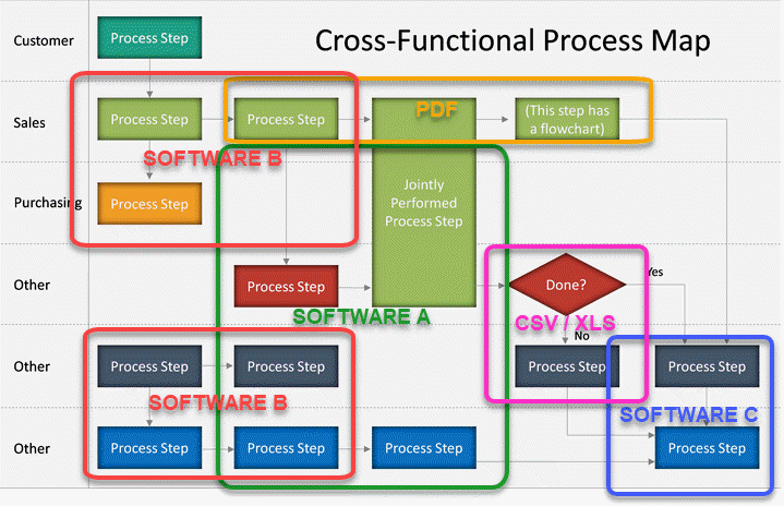
Action 4 – Technology Map
The last step in preparing for a digital transformation is to look at technology. Now that your ideal workflow is identified, it’ll be easy to map your existing technology over top of it. The documentation you produced earlier will help you do this. You’ll know the types of data, the tools or data types it’s contained in (PDF vs Excel vs CAD, etc).
When you go through this process, you’ll start to see where your technology lacks. If you see a lot of CSV, PDF or other excel workflows, they’re good indications that there’s issues. You’ll also see areas where there’s overlap. These are processes or tasks that have multiple options. Those are other areas to take note and look for improvement.
Your Digital Transformation Begins Now
The effort involved in the above activities is not trivial. While it only cost time, it does take a lot of it. To do this properly you’ll want to engage a lot of your coworkers and get their feedback.
With the documentation from these processes, you have a litmus test to perform on all future technology decisions. Purchases or initiatives all can be held this workflow to see how it fits.
In my next article, we’ll start getting into what the next steps are and how to select technology. After all, identifying what we are trying to do at a high level and documenting our workflows doesn’t change a lot all by itself. At some point to get to digital transformation we need to start intentionally and thoughtfully realigning our technology.
There’s a lot of buzzwords in the construction space. Digital Transformation…Industrialized Construction…Machine Learning….Generative Design…Augmented Reality…Drones…Robotics….and the list goes on. So what do you do? Today? Tomorrow? Next year? What actions do you take to prepare for a an unknown future? All while managing the challenges of your current projects, staff, backlog and cashflow.
I use the mechanical engineering/contracting industry in my examples. However the essence of what I’m about to say is applicable to almost any contractor. If you don’t have an unlimited budget, time and/or resources, knowing how to prepare for an uncertain future in the heat of battle can be alarming.
But it doesn’t have to be. You don’t need a crystal ball. You don’t need unlimited overhead and staff to properly prepare yourself and prevent yourself from becoming obsolete from business disruptors. What you need is a good plan. A plan that helps you understand what’s happening, why it’s happening and most importantly how to make the correct turns when you’re not sure exactly where you need to navigate.
The problem…
The contracting business is changing. This is creating a few big challenges to maintaining profitability and efficiency. To survive, we need to tackle these changes head on. Don’t worry, it’s not that hard.
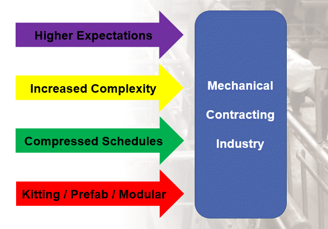
What’s Driving This?
A lot of things are driving these changes, most of which can be grouped into one of two categories. The following lists outline some of the major trends and shifts occurring.
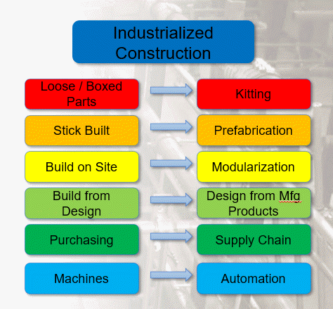
Current trends contributing to “Industrialized Construction”
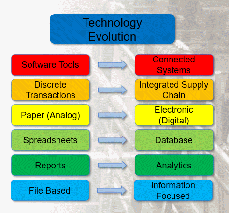
“Technology Evolution” is driven by several changes.
If you look at any of these trends individually, that all seem obvious. Not only obvious, but it’s hard to argue that any of them are negative or harmful. In fact, they all seem like good things. And they are. But when they’re all happening in unison, all these “good things” are creating a lot of the problems the industry is currently experiencing.
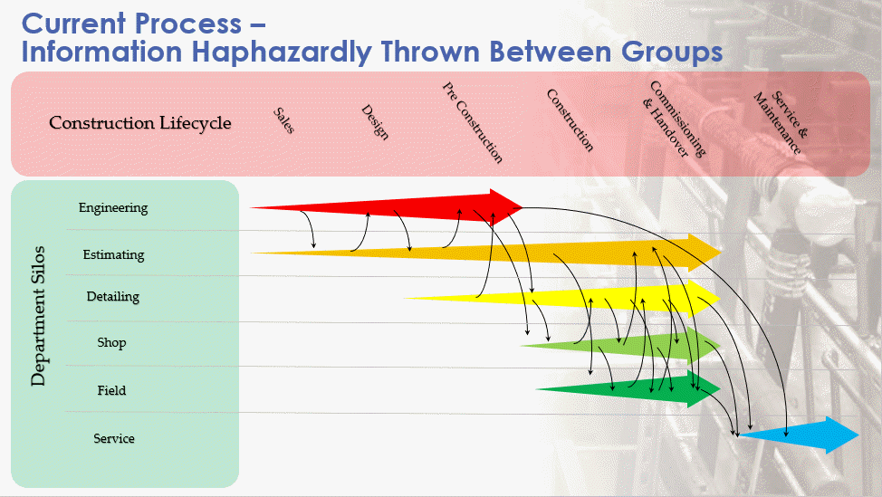
The Chaos of Today
To help manage these disruptions, it’s helpful to understand what’s happening today. Below shows an example of today’s workflow. Most groups work in silos. As they work and create more data and information over the duration of a project, they start throwing it over the fence to others within an organization. Meanwhile, other parts or the organization throw data to them.
Existing project workflows…Separate groups and processes throwing data at each other.
For most this feels like we’re juggling a ball, an egg and a chainsaw. And while we’re juggling we’re also simultaneously in the middle of a game of dodgeball.
So what happens when…
We forget to throw data to others
Too much / too little information is thrown
We don’t catch data thrown to us
Too much / too little information is caught
We miss the catch or forget to throw
Information is caught or thrown early / late
We loose information
Information was unclear
We throw or catch data to fast / slow
Data is obsolete or unapproved
We get duplicate data
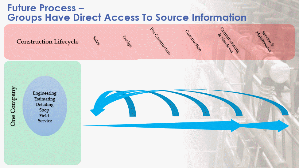
The Solution for Tomorrow
To combat these problems, we need a new process. The below is what we really want. A single stream of data everyone accesses. With this model, you don’t give anyone data, they inherently have access to the data you have which they need. It’s not a copy of the data or a report of the data. It’s access to the source data. Now, when someone needs information, they have access to it.
New project workflows…We all share in a pool of data.
Throughout the construction process, because our data is less fragmented, it’s easy to warehouse. This allows you to better inform design by pulling the historical data from the service group. Sales can now leverage this data to explain the lifecycle savings when your bid may be higher. In reality, any data from any phase can more readily be accessed from any other phase. Quality of the entire process improves when this happens.
A New Technology Stack
This “Future” process is very likely a utopian state we can never fully accomplish. At least not in our lifetime. But that doesn’t mean we can’t get closer. This doesn’t mean we can’t take a more thoughtful and meaningful approach to the solutions we use. The fact is we can. We may still have to use technology we would rather not. Things we can’t integrate as well as we’d like. But we can get closer.
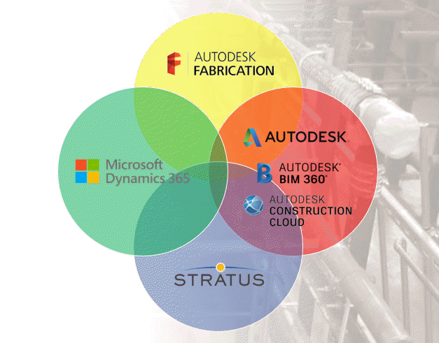
The following are examples of a technology stack portfolio. Key technologies thoughtfully selected which form the backbone of your digital process.
Example of a “Microsoft / Autodesk” based Technology Stack.
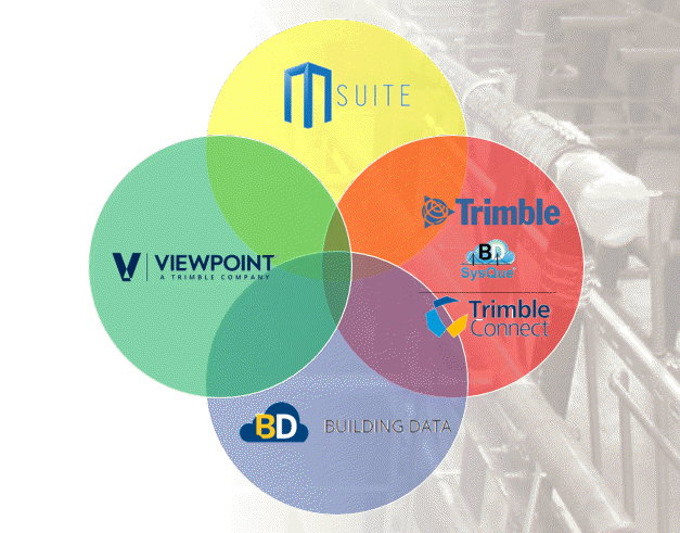
Example of a “Trimble” based Technology Stack.
These are just two examples. You don’t have to follow these examples. Your technology stack may be mixed or match differently. You may even have different solutions than those shown in the example.
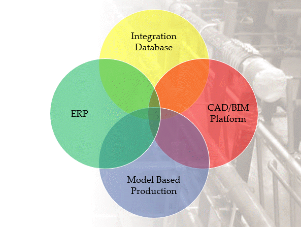
In these examples, we could use Building Data with Stratus, or Autodesk Fabrication with MSuite. Stratus and MSuite are both model based production management systems. They can both leverage your BIM platform and your BIM content and integrate with your company’s back end ERP system. For a mechanical (or electrical, general, etc.) contractor you can look at a more simplified representation below.
A good “Generic” Technology Stack Model.
Again, your model may differ. You may have two or three circles. The names in those circles may be different. But you shouldn’t have six or seven or twenty circles. It’s important that you put thought into how these systems can be used and work together. It’s also important that you understand their limitations.
This isn’t to say you don’t use a lot of additional applications. But they shouldn’t be major data stores without connectivity to some of the pillars in your technology stack. Ideally they’ll connect to one of the existing pillars but not be a major pillar in themselves.
Wrapup
This wasn’t really intended to be a roadmap. It’s more of a vision. Something you should be trying to achieve with careful thought and consideration. There’s no magic formula or combination. Nothing you should blindly copy and follow from others. Your technology stack needs to match your organization. The speed and effort to put it place based on your company culture and organizational readiness.
Regardless of how long it takes, the important thing is you’re working toward that vision. We don’t know what the future will bring in our industry. Some things will never change while others may abruptly disrupt your business. No matter what changes are forced upon you, the less impactful these changes will be the closer to this model you are. When required to, you’ll be better positions to respond in an agile manner.
In my next article, I’ll cover some things you can start doing right now that can help prepare you to implement this new model.
Most MEP contractors moving to Revit with Fabrication Parts at some point wrestle with renumbering parts. You can purchase tools or add-ins to make this easier or even write your own with Dynamo or C#.
But most contractors aren’t coders. And buying more software can also be a challenge. The good news is that those are not your only options, There’s some well written FREE Revit Add-Ins that make this a breeze.
Required Tools
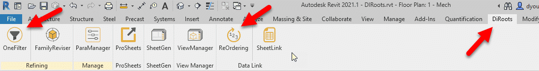
Head over to DiRoot’s web site (https://diroots.com/) and download the OneFilter Add-In found here and the ReOrdering Add-In found here.
Once installed, you’ll find the tools in the DiRoots Ribbon in Revit along with any of their other tools you may have installed.
Getting Started
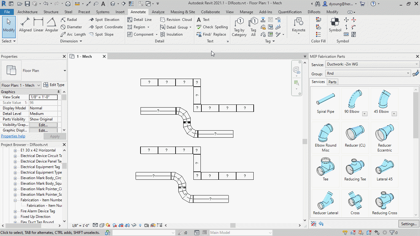
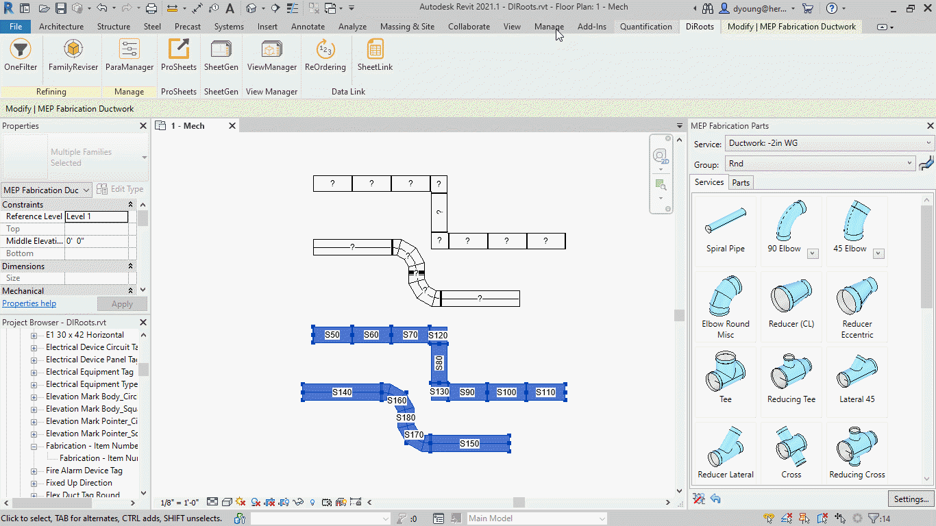
The following image shows 2 runs of Rectangular and 2 runs of Round duct work drawn in Revit using Fabrication Parts. One is drawn in a +2in WG service and the other -2in WG service. All duct has a tag configured to display the Fabrication Part’s Item Number property.
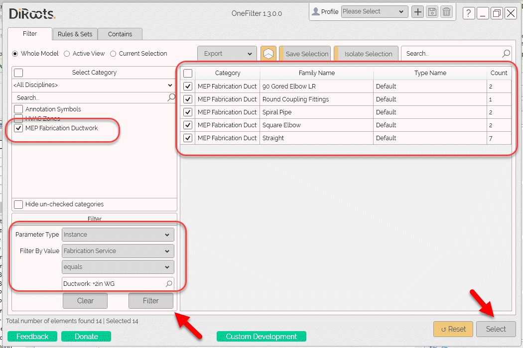
First Up – DiRoots OneFilter
Using the DiRoot’s OneFilterAdd-In, you can easily select not just Fabrication Parts, but also select them based on their properties.
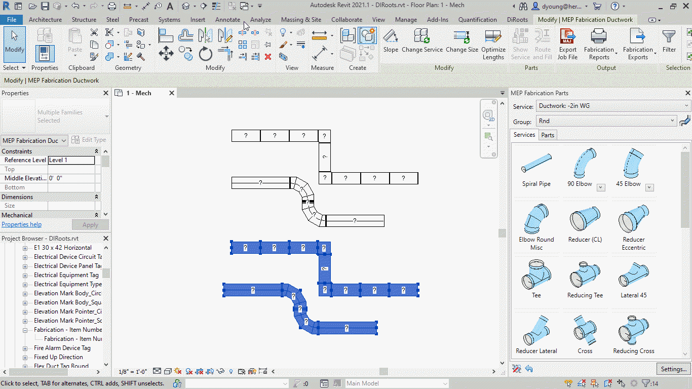
Once selected, you can see Revit selects the specified items in your model.
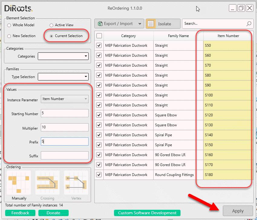
Next – DiRoots ReOrdering
Now that your desired parts are selected, you can use the DiRoots ReOrdering Add-In to renumber those parts.
After applying your renumbering parameters, you can see how Revit then displayed the updated Item Numbers for the Fabrication Parts.
Wrapup
As you can see, with a couple free (well written) utilities you can quickly and easily select and renumber your fabrication parts in Revit.
There’s a lot of other reasons beyond renumbering to use some of these Add-Ins. They’re very functional for a lot of workflows. Those uses are beyond the scope of this post but feel free to explore these Add-Ins or some of the other DiRoots tools when you get a chance. They’re some of the highest quality free Add-Ins for Revit than you’ll find anywhere.
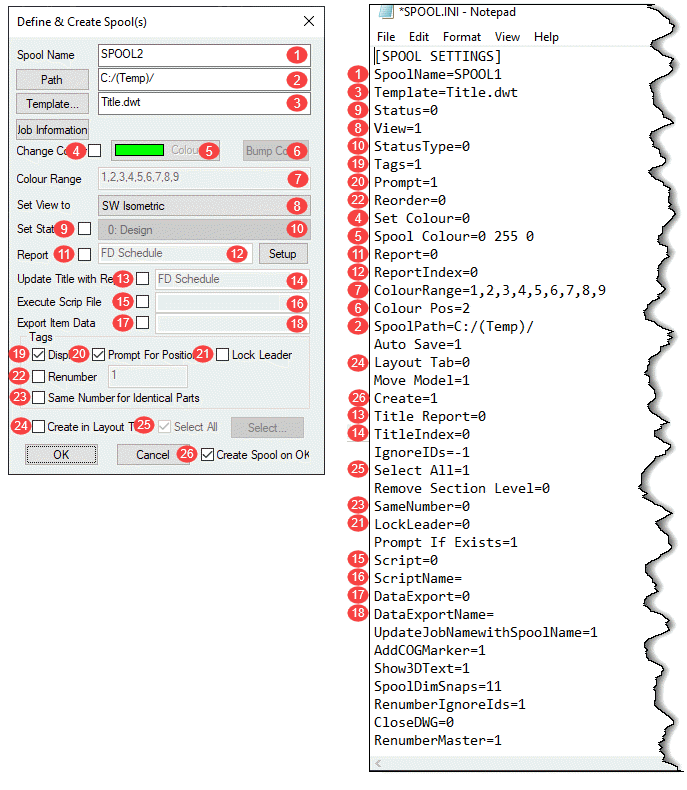
Most (but not all) of the settings in SPOOL.INI relate to the SPOOLDWG command dialog. The following image maps those fields in the dialog with those found in the SPOOL.INI file.
Values and description are listed in the below table along with some additional notes as well as settings related to spooling but not part of the SPOOLDWG dialog.
Ref.
Setting
Value
Description
Note
1
SpoolName
Alpha/Numeric
Name of Spool
3
Template
Path/Template Name
Name or Path & Name of AutoCAD Template for Spool Drawing.
9
Status
0 = Unchecked
1 = Checked
Set Status toggle in Spool Dialog.
8
View
0 = Plan
1 = SW Isometric
2 = SE Isometric
3 = NE Isometric
4 = NW Isometric
5 = None
Sets Spool drawing view type/orientation.
10
StatusType
Status Index Number
Index Number of the Status as defined in your database.
19
Tags
0 = Unchecked
1 = Checked
Set Display toggle in the Spool Dialog.
20
Prompt
0 = Unchecked
1 = Checked
Set Prompt for Position toggle in the Spool Dialog.
22
Reorder
0 = Unchecked
1 = Checked
Set Renumber toggle in the Spool Dialog.
4
Set Colour
0 = Unchecked
1 = Checked
Set Change Colour toggle in the Spool Dialog.
5
Spool Colour
RGB Value
RGB (Red Green Blue) color value of the last spool.
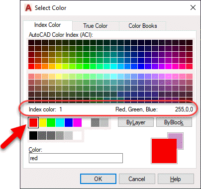
RGB Values are expressed as 3 integers, each between 0 and 255.
Use AutoCAD DDCOLOR command to determine color numbers & corresponding RGB values.
Note 1
11
Report
0 = Unchecked
1 = Checked
Set Report toggle in the Spool Dialog.
12
ReportIndex
Integer
Zero based index as listed in the drop down list in the Spool Dialog.
e.g. 0 = 1st Report, 1 = second report, etc.
7
ColourRange
Comma separated Integer List
List of Integers separated by commas.
Represent the AutoCAD Color Index numbers (ACI) of the colors to cycle through for spool colors.
Use AutoCAD DDCOLOR command to determine color numbers.
Note 1
6
Colour Pos
Integer
Zero based index of color range for the last color used on a spool.
2
SpoolPath
File Path
Folder where created spool drawings are located.
n/a
Auto Save
0 = No
1 = Yes
If Spooling to separate DWG's instead of Layouts should spool drawings should be saved after they are created.
24
Layout Tab
0 = Unchecked
1 = Checked
Set Create in Layout Tab toggle in the Spool Dialog.
n/a
Move Model
0 = No
1 = Yes
Sets if the spool be moved to 0,0,0 when creating the spool DWG's.
26
Create
0 = Unchecked
1 = Checked
Set Create Spool on OK toggle in the Spool Dialog.
13
Title Report
0 = Unchecked
1 = Checked
Set Update Title with Report toggle in the Spool Dialog.
14
TitleIndex
Integer
Zero based index as listed in the drop down list in the Spool Dialog.
e.g. 0 = 1st Report, 1 = second report, etc.
n/a
IgnoreIDs
Comma separated Integer List
List of Integers separated by commas. Integers represent the Service Type Index.
Items with these Service Type Indices will not be renumbered or have their item number displayed in the Spool. (Exception: See RenumberIgnoreIds setting)
Note 2
25
Select All
0 = Unchecked
1 = Checked
Set Select All toggle in the Spool Dialog.
n/a
Remove Section Level
0 = No
1 = Yes
Controls moving the Spool to 0,0 (X,Y) if 1/Yes or 0,0,0 (X,Y,Z) if 0/No when the Move Modelsetting is set set to 1.
23
SameNumber
0 = Unchecked
1 = Checked
Set Same Number for Identical Parts toggle in the Spool Dialog.
21
LockLeader
0 = Unchecked
1 = Checked
Set Lock Leader toggle in the Spool Dialog.
n/a
Prompt If Exists
0 = No
1 = Yes
Prompts to overwrite existing Spool DWG if it already exists.
15
Script
0 = Unchecked
1 = Checked
Set Execute Script File toggle in the Spool Dialog.
16
ScriptName
COD Script File Name
Name of COD Script File to execute on the spool.
Script name should be the file name only and NOT include the ".COD" extension.
Script file must exist in the folder specified by SCRIPTS section of MAP.INI.
Note 3
17
DataExport
0 = Unchecked
1 = Checked
Set Export Item Data toggle in the Spool Dialog.
18
DataExportName
IEX Report File Name
Name of IEX Data Export Report to run on the spool.
Report name should be the file name only and NOT include the ".IEX" extension.
Reports must exist in the proper product specific sub-folder under the reports folder specified by REPORTS section of MAP.INI.
Note 4
n/a
UpdateJobNamewithSpoolName
0 = No
1 = Yes
Updates the MAJ Job Name (Job Info) with the spool name prior to running any exports or reports.
n/a
AddCOGMarker
0 = No
1 = Yes
Calculates the Center of Gravity (COG) and inserts the COG Block (with attribute(s)) for the spool.
n/a
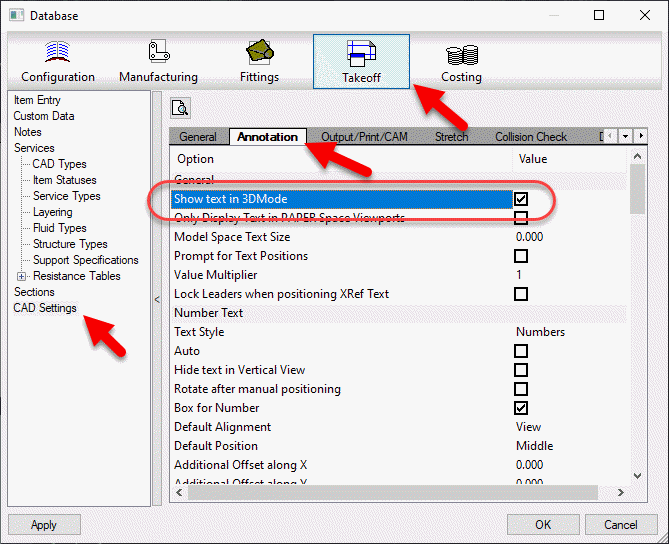
Show3DText
0 = No
1 = Yes
If showing annotations and the view is a 3d view, ensures that the database option is enabled to display in 3d.
Note 5
n/a
SpoolDimSnaps
Integer
Enumeration (Bitwise) value for which OBject Snap Modes are set when using the SPOOLDWG command.
Note 6
n/a
RenumberIgnoreIds
0 = No
1 = Yes
Renumbers the list of Ignored parts specified in the IgnoreIDs setting and stores the setting in the Alias field.
If the Alias already contains a value, the number will be appended to the value as a suffix.
n/a
CloseDWG
0 = No
1 = Yes
When spooling to separate DWG's instead of Layouts, will close the DWG after creation.
n/a
RenumberMaster
0 = No
1 = Yes
If renumbering, apply the new numbers to the Master DWG.
Note 1:
The DDCOLOR Command in AutoCAD can be used to determine ACI (AutoCAD Color Index) and/or RGB (Red Green Blue) values.
Note 2
Service Types can be found in the database editor. Use the Index Numbers in the Spool.ini settings.
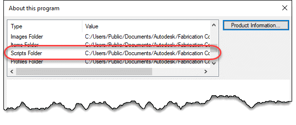
Note 3
COD Scripts must be located in the folder specified by the MAP.INI file.
Type the command APPINFO in CADmep to display a dialog which will show where the Scripts should be located.
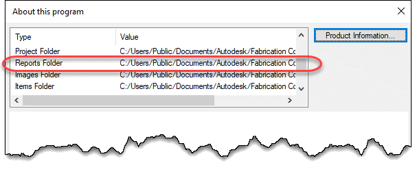
Note 4
IEX Data Export reports must be located in the software specific folder specified by the MAP.INI file. MAP.INI specifies the root folder for reports which are then found in a subfolder named based on the product using the reports. This makes knowing the exact reports folder a little difficult when looking in the MAP.INI file.
Tp more easily find the exact report folder, type the command APPINFO in CADmep to display a dialog which will show where the Scripts should be located.
Note 5
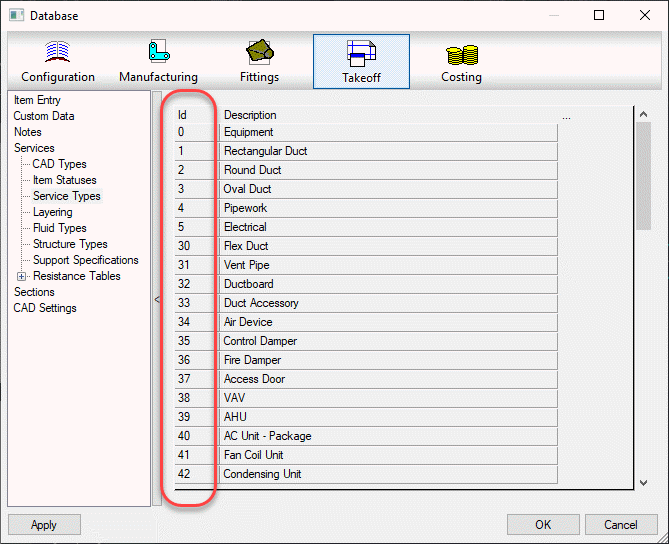
The database setting this option controls can be found in the database editor under Takeoff -> CAD Settings -> Annotation.
Note 6
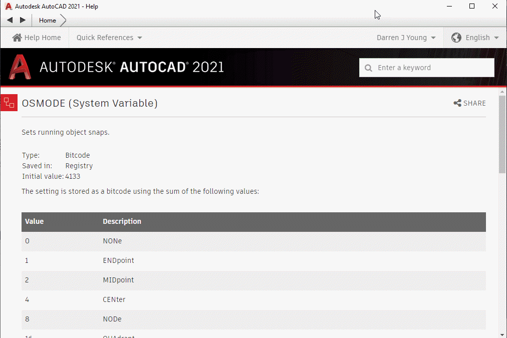
To understand how bitcoded values work for the Snap modes, look up the OSMODE system variable in AutoCAD’s Help system.
I’ve made a couple updates to the Autodesk Fabrication script libraries. If you use them, you can download updated versions from here.
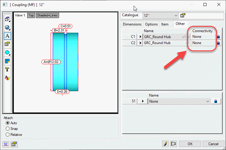
Scripts have been updated to include the Connector Material property found on CID/Patterns 522, 1522 & 2512 as shown below…
This property is intended to be used by a connector to specify a alternate material the connector can connect to. This allows a coupling to connect to alternate materials such as with transition couplings.
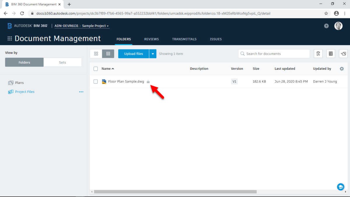
If you’d like to move you AutoCAD workflow to BIM360, you can now easily accomplish this. It’s really quite simple and requires a couple things….
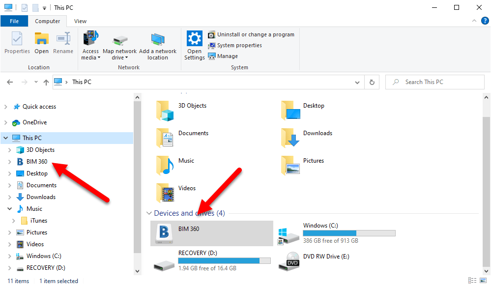
First, you nee to install the Autodesk Desktop Connector. This adds a BIM360 “Drive” to your computer much like OneDrive, Google Drive, Dropbox, etc. This BIM360 drive provides access to your BIM360 Projects that you’ve been granted access to from your BIM360 Administrator.
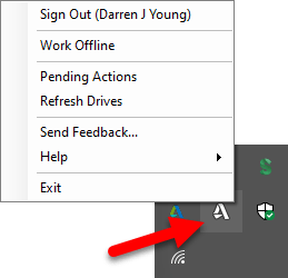
Once the Autodesk Desktop Connector is installed, you can access your BIM360 projects from this drive. You may need to login first to see your projects. You can do this by right-clicking on icon in the System Tray.
You can get the Autodesk Desktop Connector using this link.
Second, there’s a new utility called File Locking for Autodesk BIM360. This utility allows AutoCAD to “lock” the drawings you open on BIM360 so that no others can edit them at the same time.
You can download and install the File Locking for Autodesk BIM360 from the Autodesk App Store using this link.
When you now open a DWG from the BIM360 drive, BIM360 will lock the DWG and prevent others from editing it at the same time.
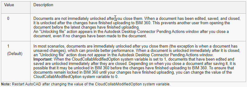
A final word….Once the File Locking utility is loaded, you can use the CloudCollabModifiedOption system variable to control how file locking is handled when you close the DWG in AutoCAD. Details here…