Autodesk Fabrication – Determining C1/C2 Connectors in Revit

Fabrication Parts in Revit allow you to edit their connectors just like in CADmep. However, unlike CADmep, you can’t simply hover over a connector to determine if it’s C1 or C2.

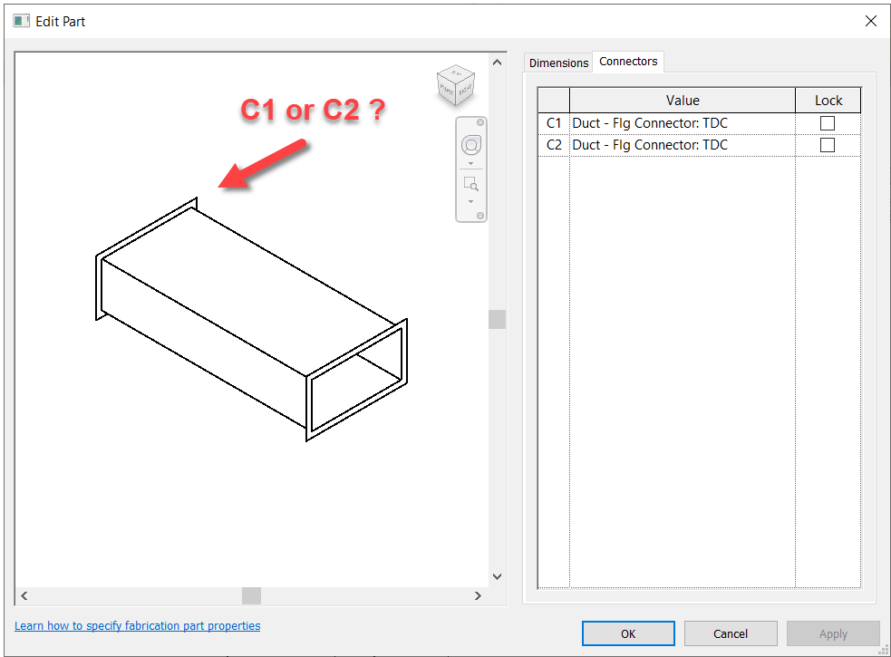
So if you need to change a connector, you’re essentially guessing which one to change. Trial and error is at best 50% unless you’re lucky.

So how can you improve this “guessing” based workflow?

Thankfully I have a great network of people smarter than myself. I often get the credit for sharing the information but really, the credit belongs to those who show me. In this case, two of my industry friends showed me ways to improve the odds.


Method 1 – Slope

For this first method, credit goes to Liz Fong from MacDonald Miller. When you place a piece of straight pipe or duct, when you select it you’ll see a Slope indicator (< or >). This by default points to the C1 connector.

Duct/Pipe placed defaults the Slope symbol pointing to C1
Duct/Pipe mirrored also defaults the Slope symbol pointing to C1

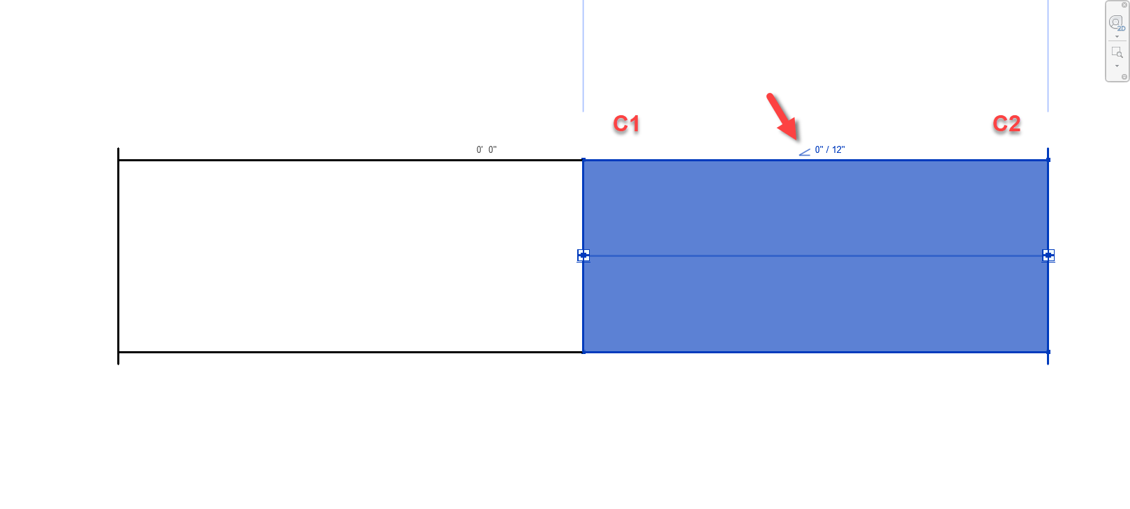
There’s a couple downsides to this approach that may apply in some scenarios….

  1. This doesn’t work for fittings. Only Straight Pipe/Duct.
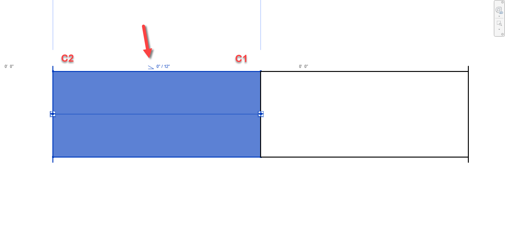
  2. If you click the Slope Symbol, it changes direction and is no longer accurate.
    • This should really only affect Plumbing or sloped Grease Duct systems. Otherwise there’s not a lot of reason to change direction on a non-sloped system.
    • Symbol could still be accidentally clicked and reversed anyway and then be wrong.
  3. Once changed, Slope symbol direction is remembered and there’s no good way to “reset” it.

Still, despite the downsides of this approach, I’m going to go out on a limb and suggest that even on a plumbing system, less that 50% of the slope symbols will be changed from their default. This alone makes this method better than a 50/50 guess like before.


Method 2 – View Cube/Viewing Direction

This next method takes slightly more work, but is almost 100% accurate. Credit for this method goes to Alina Y. from JH Kelly.

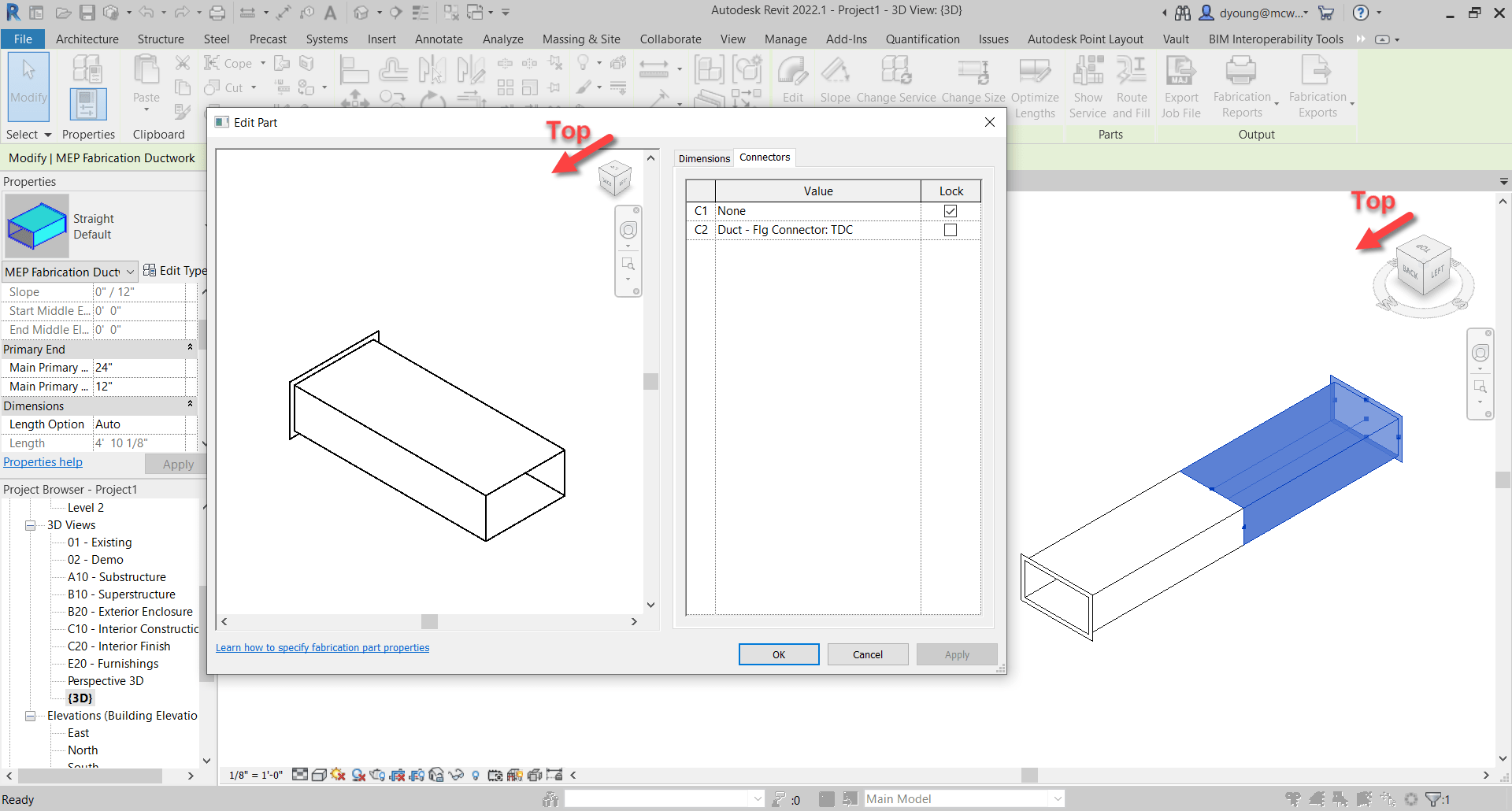
In short, from a 3d view, if you make sure the View Cube in the Part Editor window is aligned to the Revit View you’re in, the fittings is oriented in the same direction in the editor as in Revit. You can then select the connector in the Part Editor window and it highlights the connector end associated with it.

Duct/Pipe placed in Revit matches the editor when View Cubes are aligned. Selected Connector highlights.
Duct/Pipe mirrored in Revit matches the editor when View Cubes are aligned. Selected Connector highlights.

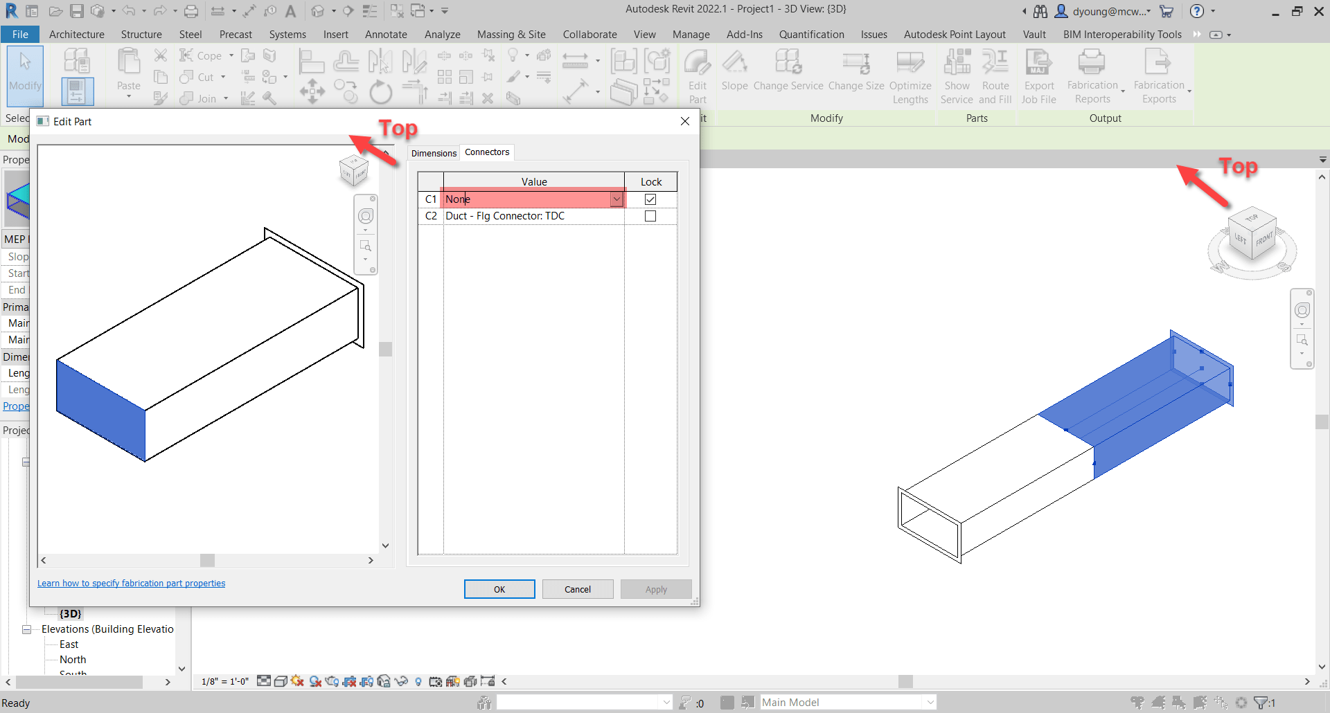
This method is almost fool proof and has a few benefits over the sloped method we showed earlier.

  1. Works on Fittings in addition to Straight Duct/Pipe.
  2. Slope direction doesn’t matter.

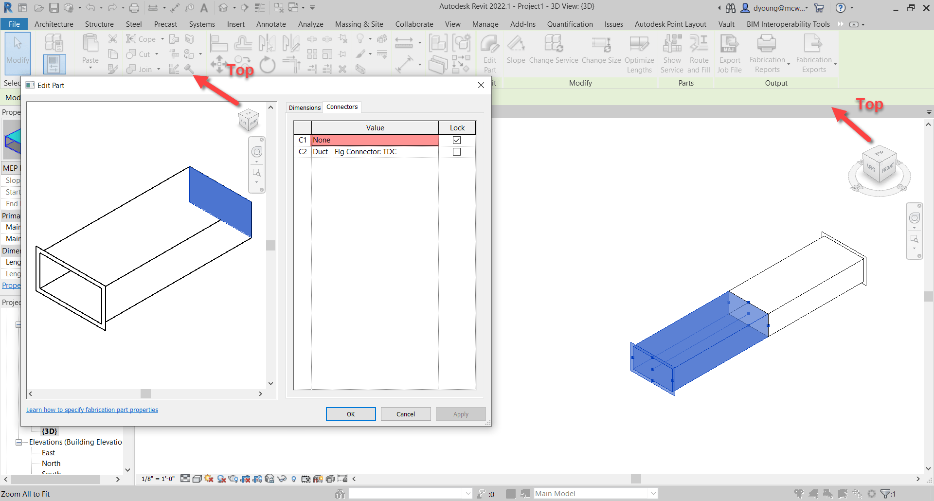
But we did say Almost. Where this method fails, is if the View in Revit is redefined.

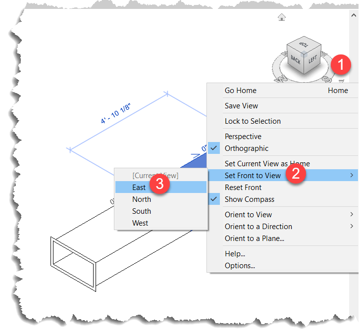
When you set a new Front View, the view in Revit no longer matches the orientation in the Part Editor window as seen in the following image…

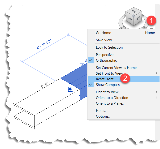
Luckily, this is easily remedied by simply resetting the Front View in Revit.

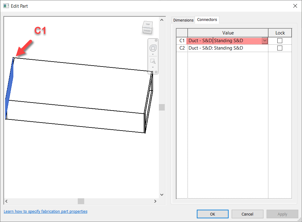
This method also works in Plan and Elevation Views with a slight twist. There’s no View Cube in the Revit window so it’s up to you to understand which viewing angle Revit is in. Next, you can make the View in the Item Editor match but when you look at a connector straight at the edge, you don’t see it highlight. You can then hold the SHIFT key and use the Middle-Mouse Button to slightly rotate the view so that you can see the connector that’s highlighted.

Here you can see what that looks like…


Summary

While not as quick and efficient as hovering over a connector in CADmep, either of these methods or even used in combination can increase your odds of changing the Correct connector on the first try.

While method #2 is more fool proof than method #1, there’s a reason I explain both and here’s how I’d use them both.

For non-sloped systems, the chances the slope symbol is reversed is very low. Because you’re likely selecting the part anyway to edit a connector, a quick glance is all you need to know which connector to change. Quick and easy for straight part on non-sloped fittings. No fuss. No muss. In this scenario, Method #1 is super quick.

For fittings and sloped systems, I would then shift to Method #2. Take a little more time, but it’s certainly quicker than being wrong 1/2 the time and then undoing the connector you just changed and then changing the other. That “trial and error” method results in 3 connector changes when you guess wrong. This is where Method #2 really shines…you get it right every time. If you’re Front View happens to be redefined, it’s easily rest.

Thanks again to Liz Fong (MacDonald-Miller) and Alina Y (JH Kelly) for their great input in coming up with these methods. They’re two of my favorite “Go To” people when I get stumped or need a little help orienting my thoughts.

SPOOL.INI Explained

Most (but not all) of the settings in SPOOL.INI relate to the SPOOLDWG command dialog. The following image maps those fields in the dialog with those found in the SPOOL.INI file.

Values and description are listed in the below table along with some additional notes as well as settings related to spooling but not part of the SPOOLDWG dialog.

Ref.SettingValueDescriptionNote
1SpoolNameAlpha/NumericName of Spool
3TemplatePath/Template NameName or Path & Name of AutoCAD Template for Spool Drawing.
9Status0 = Unchecked
1 = Checked
Set Status toggle in Spool Dialog.
8View0 = Plan
1 = SW Isometric
2 = SE Isometric
3 = NE Isometric
4 = NW Isometric
5 = None
Sets Spool drawing view type/orientation.
10StatusTypeStatus Index NumberIndex Number of the Status as defined in your database.
19Tags0 = Unchecked
1 = Checked
Set Display toggle in the Spool Dialog.
20Prompt0 = Unchecked
1 = Checked
Set Prompt for Position toggle in the Spool Dialog.
22Reorder0 = Unchecked
1 = Checked
Set Renumber toggle in the Spool Dialog.
4Set Colour0 = Unchecked
1 = Checked
Set Change Colour toggle in the Spool Dialog.
5Spool ColourRGB ValueRGB (Red Green Blue) color value of the last spool.

RGB Values are expressed as 3 integers, each between 0 and 255.

Use AutoCAD DDCOLOR command to determine color numbers & corresponding RGB values.
Note 1
11Report0 = Unchecked
1 = Checked
Set Report toggle in the Spool Dialog.
12ReportIndexIntegerZero based index as listed in the drop down list in the Spool Dialog.

e.g. 0 = 1st Report, 1 = second report, etc.
7ColourRangeComma separated Integer ListList of Integers separated by commas.

Represent the AutoCAD Color Index numbers (ACI) of the colors to cycle through for spool colors.

Use AutoCAD DDCOLOR command to determine color numbers.
Note 1
6Colour PosIntegerZero based index of color range for the last color used on a spool.
2SpoolPathFile PathFolder where created spool drawings are located.
n/aAuto Save0 = No
1 = Yes
If Spooling to separate DWG's instead of Layouts should spool drawings should be saved after they are created.
24Layout Tab0 = Unchecked
1 = Checked
Set Create in Layout Tab toggle in the Spool Dialog.
n/aMove Model0 = No
1 = Yes
Sets if the spool be moved to 0,0,0 when creating the spool DWG's.
26Create0 = Unchecked
1 = Checked
Set Create Spool on OK toggle in the Spool Dialog.
13Title Report0 = Unchecked
1 = Checked
Set Update Title with Report toggle in the Spool Dialog.
14TitleIndexIntegerZero based index as listed in the drop down list in the Spool Dialog.

e.g. 0 = 1st Report, 1 = second report, etc.
n/aIgnoreIDsComma separated Integer ListList of Integers separated by commas. Integers represent the Service Type Index.

Items with these Service Type Indices will not be renumbered or have their item number displayed in the Spool. (Exception: See RenumberIgnoreIds setting)
Note 2
25Select All0 = Unchecked
1 = Checked
Set Select All toggle in the Spool Dialog.
n/aRemove Section Level0 = No
1 = Yes
Controls moving the Spool to 0,0 (X,Y) if 1/Yes or 0,0,0 (X,Y,Z) if 0/No when the Move Modelsetting is set set to 1.
23SameNumber0 = Unchecked
1 = Checked
Set Same Number for Identical Parts toggle in the Spool Dialog.
21LockLeader0 = Unchecked
1 = Checked
Set Lock Leader toggle in the Spool Dialog.
n/aPrompt If Exists0 = No
1 = Yes
Prompts to overwrite existing Spool DWG if it already exists.
15Script0 = Unchecked
1 = Checked
Set Execute Script File toggle in the Spool Dialog.
16ScriptNameCOD Script File NameName of COD Script File to execute on the spool.

Script name should be the file name only and NOT include the ".COD" extension.

Script file must exist in the folder specified by SCRIPTS section of MAP.INI.
Note 3
17DataExport0 = Unchecked
1 = Checked
Set Export Item Data toggle in the Spool Dialog.
18DataExportNameIEX Report File NameName of IEX Data Export Report to run on the spool.

Report name should be the file name only and NOT include the ".IEX" extension.

Reports must exist in the proper product specific sub-folder under the reports folder specified by REPORTS section of MAP.INI.
Note 4
n/aUpdateJobNamewithSpoolName0 = No
1 = Yes
Updates the MAJ Job Name (Job Info) with the spool name prior to running any exports or reports.
n/aAddCOGMarker0 = No
1 = Yes
Calculates the Center of Gravity (COG) and inserts the COG Block (with attribute(s)) for the spool.
n/aShow3DText0 = No
1 = Yes
If showing annotations and the view is a 3d view, ensures that the database option is enabled to display in 3d. Note 5
n/aSpoolDimSnapsIntegerEnumeration (Bitwise) value for which OBject Snap Modes are set when using the SPOOLDWG command. Note 6
n/aRenumberIgnoreIds0 = No
1 = Yes
Renumbers the list of Ignored parts specified in the IgnoreIDs setting and stores the setting in the Alias field.

If the Alias already contains a value, the number will be appended to the value as a suffix.
n/aCloseDWG0 = No
1 = Yes
When spooling to separate DWG's instead of Layouts, will close the DWG after creation.
n/aRenumberMaster0 = No
1 = Yes
If renumbering, apply the new numbers to the Master DWG.

Note 1:

The DDCOLOR Command in AutoCAD can be used to determine ACI (AutoCAD Color Index) and/or RGB (Red Green Blue) values.


Note 2

Service Types can be found in the database editor. Use the Index Numbers in the Spool.ini settings.


Note 3

COD Scripts must be located in the folder specified by the MAP.INI file.

Type the command APPINFO in CADmep to display a dialog which will show where the Scripts should be located.


Note 4

IEX Data Export reports must be located in the software specific folder specified by the MAP.INI file. MAP.INI specifies the root folder for reports which are then found in a subfolder named based on the product using the reports. This makes knowing the exact reports folder a little difficult when looking in the MAP.INI file.

Tp more easily find the exact report folder, type the command APPINFO in CADmep to display a dialog which will show where the Scripts should be located.


Note 5

The database setting this option controls can be found in the database editor under Takeoff -> CAD Settings -> Annotation.


Note 6

To understand how bitcoded values work for the Snap modes, look up the OSMODE system variable in AutoCAD’s Help system.