CAMduct Machine Setup – Axis & Orgin
One of the things that can make machine setup difficult in CAMduct is setting up the coordinate system. This coordinate system must reflect the actual configuration of the machine. Some machines can be reconfigured to swap the axes or set the origin to any corner. This lets you configure the machine to match the software. Others can’t be reconfigured and require you to configure the software to the machine.
It doesn’t really matter where the origin is on the machine, just as long as the configuration in CAMduct matches. Matching the machine isn’t difficult, just as long as you understand what’s happening.
Default Origin and Axis Orientation
In the Machine Setup Dialog, the default Origin is in the lower left. Take a look at the settings and note the X-Axis and Y-Axis directions.
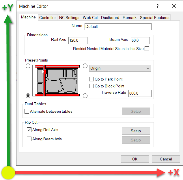
From this configuration, here’s a simulation of the code that’s generated.
If this configuration doesn’t work for your machine, it typically means the machine has a different origin and/or Axis configuration.
Coordinates Rotated 90 Degrees / X-Axis & Y-Axis Swapped
This next configuration rotates the coordinates which results of the X-Axis and Y-Axis being swapped. It also looks like the Origin location changes given the picture, but that’s not the case. This is why Machine Setup can be confusing. This picture does NOT change the origin location. This will become clear shortly.
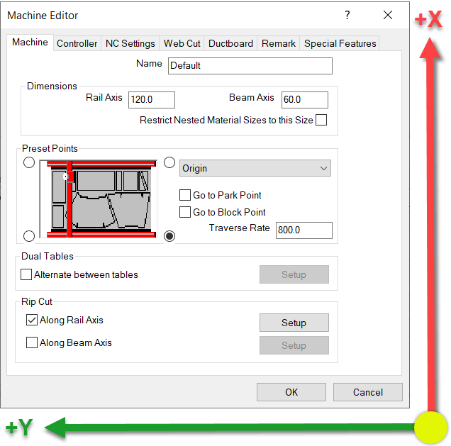
What you’ll notice here when looking at the code, is that the Part is Still oriented in the Lower Left Corner of the sheet. However, the X-Axis and Y-Axis are swapped. Additionally, looking at the code on the right, you’ll see how the Y-Axis goes into Negative coordinates. This also isn’t what most machines want, they typically work in positive coordinates but this is easily fixed which we’ll show a little later.
Coordinates Rotated 180 Degrees / X-Axis & Y-Axis Mirrored
This next configuration sets the X-Axis and Y-Axis so that both are mirrored…or rotated 180 degrees.
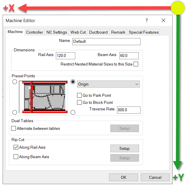
Looking at the simulation of this configuration, you’ll see both X & Y Axes are using negative coordinates.
Here the both Axes are in negative coordinates and the Part is still located in the lower left of the sheet. Again, not what a machine wants typically, but easily fixed and covered in a little bit.
Coordinates Rotated 270 Degrees / X-Axis & Y-Axis Reversed
Here’s the last configuration. Again notice which way the Axes are oriented.
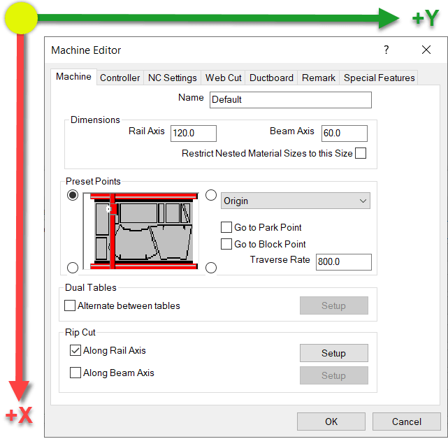
In this next configuration, the X-Axis and Y-Axis are reversed like before. But this time, the X-Axis is in negative coordinates where as the Y-Axis is in positive coordinates.
Fixing Negative Coordinates
What makes this hard, is that the setting in the dialog makes you think you’re moving the origin of the code. You are not. You’re merely rotating the coordinate system. This is critical when using a machine tool like a Lockformer or Vulcan that uses Trimble’s TookShop controller (formerly called Vulcan). Those are a couple of the most common machines where the X & Y Axis are reversed.
When you look at the simulations, the sheet is still oriented in the same location and the part starts in the same location on the sheet.
You can look at the configuration and see that the Rail is set to the long direction and the Beam is set to the Short setting. Remember this….it’ll be important in just a bit.
For this example, we’ll again use the 90 Degree rotated configuration (our second example) where the X & Y are reversed and the Y-Axis coordinates are negative. You can see in the code, that the Y-Axis is the LONG sheet dimension due to the rip cut along the Rail that’s cut at the end of the program.
Because the Rail Rip Cut starts at Y=0.0 and goes to Y-120.0, you can see that the Origin is still on the left side of the sheet not the right as the configuration screen suggests. Here’s a reminder of the Axis directions…
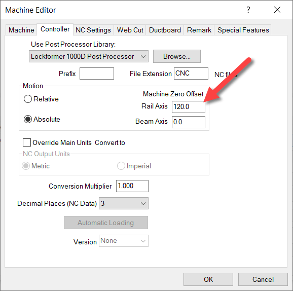
How, when you run a simulation on this setup, you’ll see the Y-Axis is still the long sheet direction, but they’re all positive coordinates.
Notice on the simulation that the part is STILL on the left side of the sheet and because we shifted the Origin to the right side the Rip cut along the Rail (long side) goes from Y=120.0 to Y=0.0.
You’ve now successfully swapped the X&Y Axis and corrected the coordinates to they’re all in positive units. From here, you can go back and finish configuring all your other preferences like where the parts get nested on the sheet, starting cut location, etc.