Fabrication Job Contains No Parts – Possible Fix?

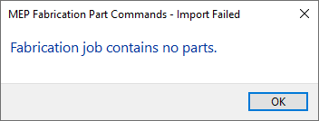
Have you ever tried importing an MAJ into Revit and received the following error….Fabrication Job Contains No Parts.

There’s a lot of reasons this can occur and it’s NEVER because there are no parts. So much for Autodesk’s QA/QC and Error checking.

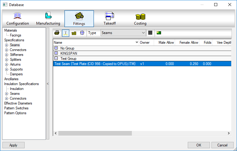
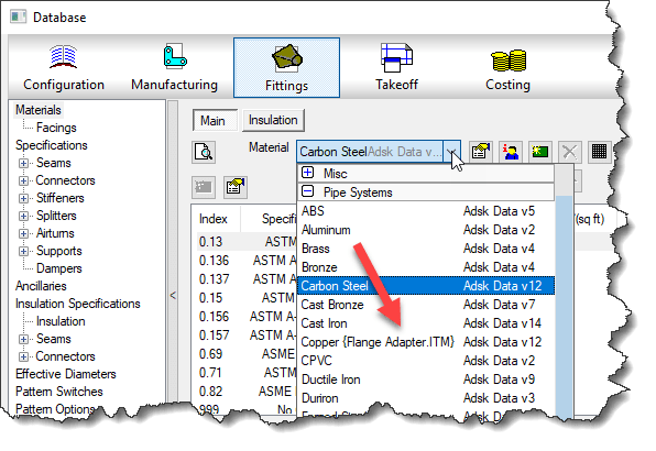
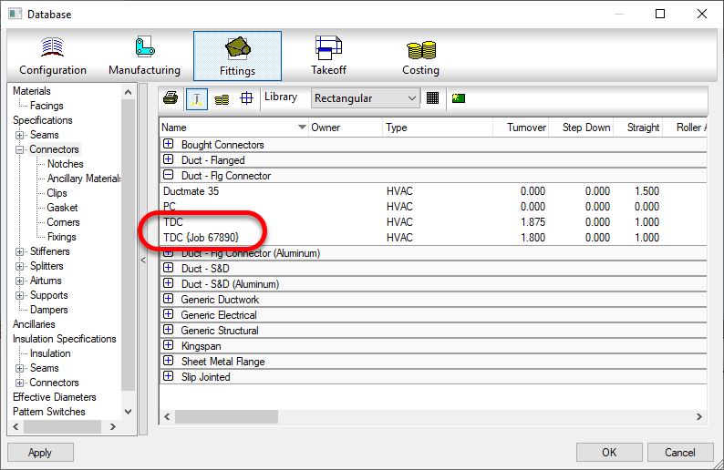
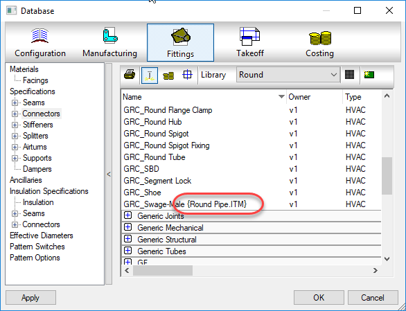
You may see this most commonly because parts used in the model contain data that’s no longer in your database. You’ve likely noticed from time to time database entries with curly braces around parts of the name like the following…

This happens when an entry in the database is used by an ITM but the database entry itself later gets deleted. Information is cached within the ITM so when it’s accessed, it creates a Proxy entry in your database if it was missing. Within the {Curley Braces} is the name of the object that created the entry.

While CADmep, ESTmep and CAMduct handle this fairly gracefully, Revit on the other hand does not. When it attempts to load an MAJ, it sees these entries and notices they’re missing from your database and prohibits you from importing the MAJ file. Revit thinks the database doesn’t match the MAJ and stops you cold!

A Possible Fix

If this is cause for the import error, you can use the following COD script to potentially work around the issue….

Take the following script and run in in CADmep, ESTmep or CAMduct. You should be logged in with Administrative Permissions while doing this. This script isn’t fixing Revit or the MAJ. What it’s doing is loading ALL the ITM’s from your Database Library into memory.

The process of loading all these ITM’s into memory creates all these proxy entries in your database. This way, when Revit attempts to import the MAJ, the data associated with those ITM’s are most likely present in your Database configuration. In many cases then results in a successful import of the MAJ.

If the Revit file you are importing the MAJ into already points to a Fabrication Configuration, you should reloaded the configuration FIRST before attempting to import the MAJ.

If for some reason this process still doesn’t work, verify that Revit is reading from the same database location as the version of CADmep, ESTmep or CAMduct where you ran the COD script.

In the event it still doesn’t work, there may be other reasons for the failure but this is often the most common, especially with MAJ’s created recently.

If it does work, you’ll want to use the other scripts I provide on this site to help analyze your database. You likely deleted those database entries in the first place for a reason. You either didn’t realize they were needed, or you didn’t know where they were used to repoint those ITM’s to a proper substitute. Those scripts can help you find which ITM’s use which database entries.

Hope this helps.

Autodesk Fabrication: Best Practice #13

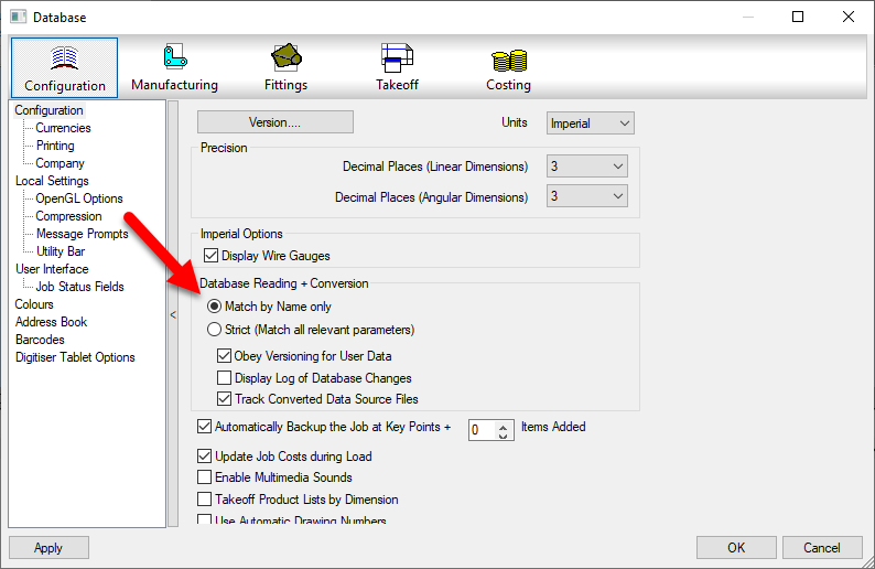
Use “Match by Name only” in Database Settings

Do you have issues with duplicate entries in your Fabrication Database? These could be proxy entries…those followed by text enclosed within {brackets}. Or they could be identical..if someone made the proxy item permanent,

This can be caused by using the Strict matching setting in your database setting. It’s recommended to use Match by Name only.

When you use Strict naming, when you open drawings or MAJ files, the database settings within those files are compared to those in your configuration. If the data is deemed relevant and it varies, even something as small as a number 3 decimals vs. 4 decimals can add another entry into your configuration.

When using Match by Name only, as long as the name (and group) matches, the entry is considered the same and you don’t end up with duplicate entries.

Merging Autodesk Fabrication Databases (Method 4 of 4)

Warning: This is last part (4 of a 4) in a series on merging Autodesk Fabrication Databases. Autodesk Fabrication software is extremely powerful and flexible but that also makes it very fragile. Use the below guidance with caution. I highly recommend backing up your configuration before attempting anything I’ve recommended. It never hurts to have a firm grasp of how Autodesk Fabrication functions from an administrative perspective. Consider yourself warned!

Method 4: MERGEDB (CAMduct only)

This last method is very quick and powerful but only available in CAMduct. If you’re not a CAMduct user, simply download and install to perform this process while in the 30-day trail period.

This method doesn’t let you pick and choose individual database entries but you can pick certain database types and quickly merge all of them into a new configuration. Unlike prior methods were you typically started in the old Database to export an *.IOX / *.IEZ file or create a Proxy ITM first, in this process, you start with the database you want the items to be imported into.

In addition to make of the database entries Method 1 supported, this method also supports these additional entries.

CutoutsLeadsRates
FacingsMaterialsSilencers
Hanger SpecificationsNotchesVanes

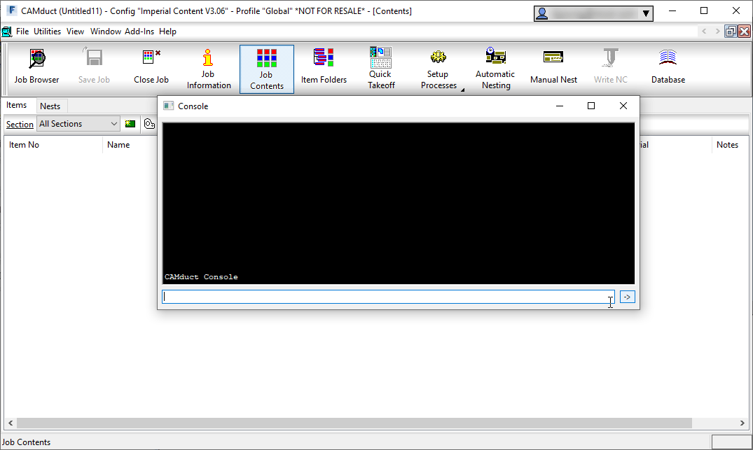
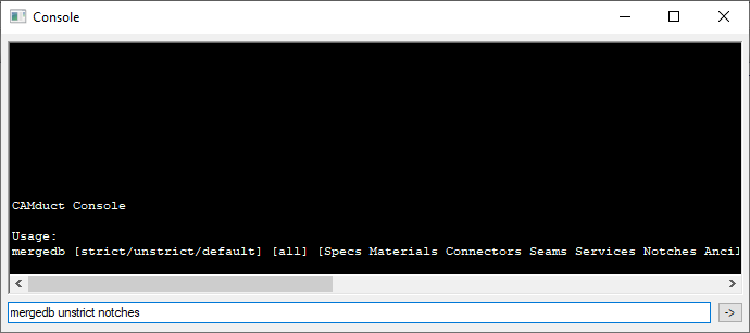
To use this method, start CAMduct and type CTRL-SHIFT-C to display the command window as shown below.

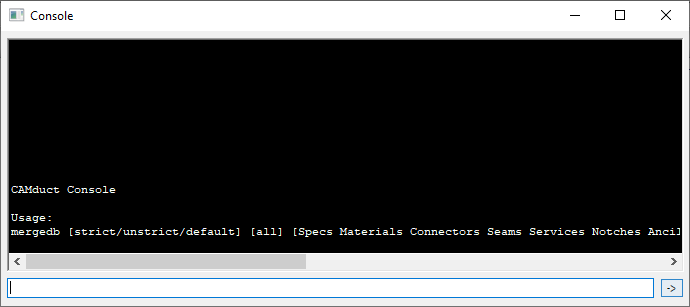
From the command window, type MERGEDB and press <Enter>. This doesn’t do anything other than tell you the data the command needs as shown below. The Strict/Unstrict options tell the merge process if it should only look at the name or the data to determine if it’s duplicate. If you choose strict and the items are already in your database, something as simple as 3 vs 4 digits after a decimal will cause a duplicate entry. In most cases, unstrict is all that’s required.

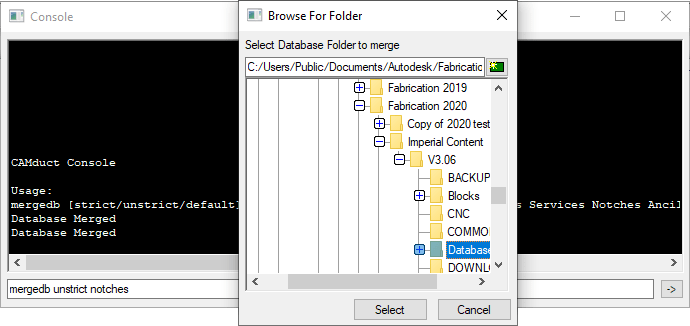
For this example, we’ll type MERGEDB UNSTRICT NOTCHES to import all the notches from one database to another as shown below.

When you press enter, you’re prompted to select a folder. You should select the Database folder of the old database you want to merge into your current database.

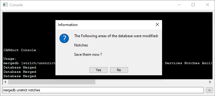
If new items are found, you’ll be notified and prompted if you want to save the changes or not.

Upon completion of the merge, you’ll need to go to those items in your database and make permanent any you intend to keep and remove those you didn’t want.

Pros:
> Only way to import some database entry type.
> Easiest way to merge the bulk of 2 database together.
> Extremely fast and efficient.
Cons:
> Requires CAMduct.
> Can not pick and choose database entries, only database types.
> Requires post merge cleanup of deletion or making entries permanent

Autodesk Fabrication: Best Practice #6

Don’t PURGE or COMPACT Your Database When In Use

A Fabrication Database that’s well managed should have changes being made. This can mean things like materials, specifications, services, connectors and such may be occasionally deleted and removed. If there are proxy items in your database that have {brackets} around them, they should be made permanent or removed as well.

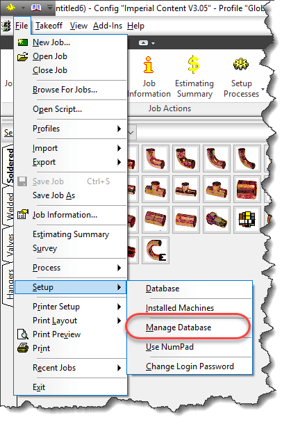
The way to do this is to PURGE and/or COMPACT your database, You can do this by typing PURGEDB on AutoCAD’s command line or by selecting File -> Setup -> Manage Database from ESTmep or CAMduct as sown in the following image.

When you initiate this process, you’ll be presented with a standard “Backup Your Database…” warning which you can click OK to.

From there, you are then presented with the following dialog.

Items that show up here are the ones that show up with {Brackets} in your database, They should either be made permanent or removed in a well managed system.

The Make Permanent option is fairly safe. The items are in your database already there and already have indexes assigned.

On the other hand, the Purge Database option will remove them from your database. When you do this, the’s a chance that some of the database indexes will change as those indexes are how the various database tables relate to each other.

If you do this while others are using the database in CADmep, ESTmep or CAMduct, they already have the database tables loaded into memory. Depending what they are doing, some activities may cause parts of the database to be reloaded while others are not. When this happens, strange things can happen to your drawing…your systems might loose their service or change services or connectors change without notice. More times than not, unless you catch it right away,by the time you find the issue you’ll need to remodel your data or retrieve it from a backup.

In a Database, records are not actually deleted so while the Purge command appears to remove items from the database, it  actually just flags them as being unused so those areas in the database can be overwritten with new data later. This is where Compacting the database comes into play. The Compact the Database Now option will rewrite and re-sequence all the database files and their indexes to recapture that unused space. Again, this causes issues for others who are currently referencing the database and doing work.

While there is danger in using these commands, they should be used to properly manage your database. The key here is to use them after hours when other users are not using the database. Another option would be to do your development work in a copy of the database so nobody is ever “using” the database you’re performing administration work in. When you’re done, you can “copy” this database to the production database but again, after hours when nobody is doing work or you could have all users log out temporarily (perhaps at lunch) and copy the database then.

To the best of my knowledge, this issue is NOT present for those of you using Revit with Fabrication parts. Revit loads in your services and content and caches it in the Revit model. It doesn’t reference the database configuration again while you work unless you manually “reload” the configuration, So unlike CADmep, ESTmep or CAMduct which may reload parts of your database just by using the software, Revit won’t do this unless you manually reload in which care it will reload everything and keep all those database sequences sin check.

If you’ve ever opened an AutoCAD drawing and your parts appeared orphaned from their services, connectors changed to things that don’t make sense or your Cast Iron NoHub Waste system suddenly reports as Rectangular Supply Air, this likely was the cause and this Best Practice is for you.

CAMduct, OPUS Parts, Edited Developments and Proxies

Two Problems….One Solution

In CAMduct using OPUS parts and/or ITM’s with developments that have had edits made to them can on occasion cause some headaches. The following process can be used to resolve 2 different issues in CAMduct, Those are….

  1. Retain edited pattern developments
  2. Eliminate proxy database entries with {curly brackets}

1) Retaining Edited Developments

It’s fairly common for CAMduct users to edit pattern developments. Occasionally, they may want to save these edited developments for later use. A good example is using a number of separate ITM’s for damper blades. Each ITM is a different size with perhaps some edits to the pattern for slots/holes for U-Bolts, notching to clear screws, etc.  A CAMduct user can use any CID Pattern for the basis of their edits. For example, they could use an Elbow CID, delete all the developments belonging to the elbow and redraw something completely from scratch. The problem with this is that if you ever try to change materials or edit the ITM in any other way, the development edits are lost and the original development is back minus your changes.

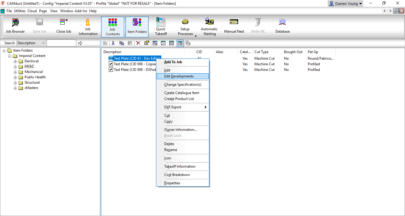
In the following image, you can see that Right-Clicking on an ITM made from CID 41 offers a couple editing options In this case, we’re going to select the Edit Developments option.
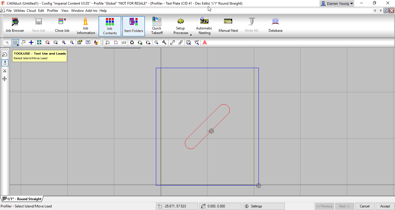
When you select the Edit Developments option, you’re brought to the OPUS Part editor shown in the next image. Here you’ll see that there’s been a 45 degree slot added to the development.
On the other hand, you can also Right-Click on the ITM and select EDIT from the menu as shown in the next image.
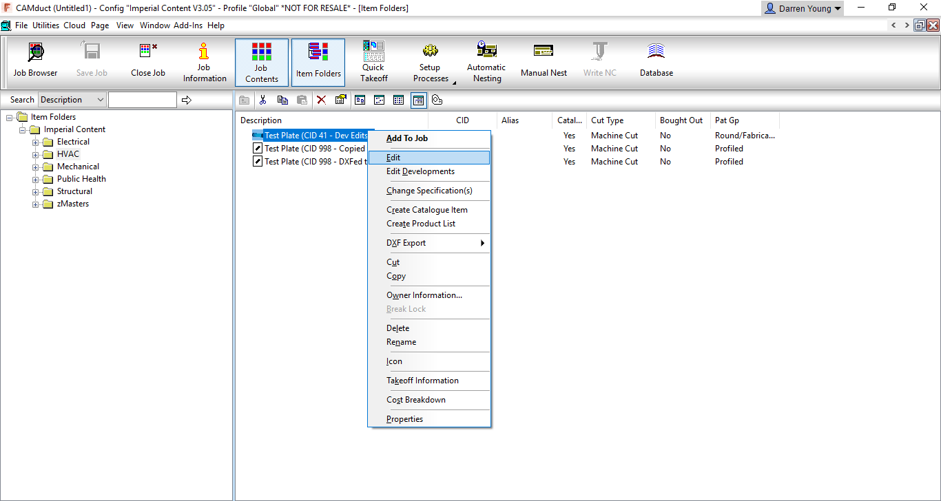
This option brings up the standard ITM editor which you should be fairly familiar with. The part you see in the ITM editor may not look anything like the development, it may look very similar or in fact be the same part developed if there were no edits made. From the ITM Editor, click the “Develop” button in the lower right and you’ll again be brought to a dialog that displays the part(s) developments. This time you’ll notice that the 45 degree slot is not shown. In fact, it’s displaying the unedited development for the CID you’ve selected based on the Dimensions, Options, etc. as entered in the ITM Editor. From the ITM editor, the dimensions, options and other settings drive the size/shape of the developments. It wouldn’t know what to do with your edits so it gets rid of them,
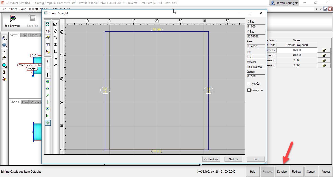
When you Edit the part in the ITM Editor, even if to change something simple as a material, the pattern gets redeveloped and the edits you made to the developments are lost. This makes ITM’s utilized this way very prone to getting wiped out of you’re not careful.

The solution to protecting these developments is to change them to a different CID pattern used exclusively for OPUS parts…CID 998 (or 0 depending how it’s created) OPUS parts contain only the development and not the originating ITM pattern. When you select the Edit option for an OPUS part, you go directly to the Opus Editor.


2) Proxy Database Entries

The other problem with edited developments is they can bring in proxy entries into your database. As an example, lets say the CID Pattern used was pointed to a Material, Connector or Seam in your database that no longer exists, was renamed or moved to a new group. As explained earlier, you can’t go back and edit the ITM to change them or your edits to the development will get wiped out.  You can change the seams/connectors/materials with a COD script to avoid this but most people are not familiar with this process. When you use this type of ITM, the old materials, seams and.or connectors that were originally used come back into your database with {brackets} around them.

Even then, a Development Part is assigned a material separate from the material on the ITM. There is no way to change the development part’s material from a COD script. You can however, change it from the Development tab of the Properties dialog.

The following image shows the Properties option when Right-Clicking on an ITM.
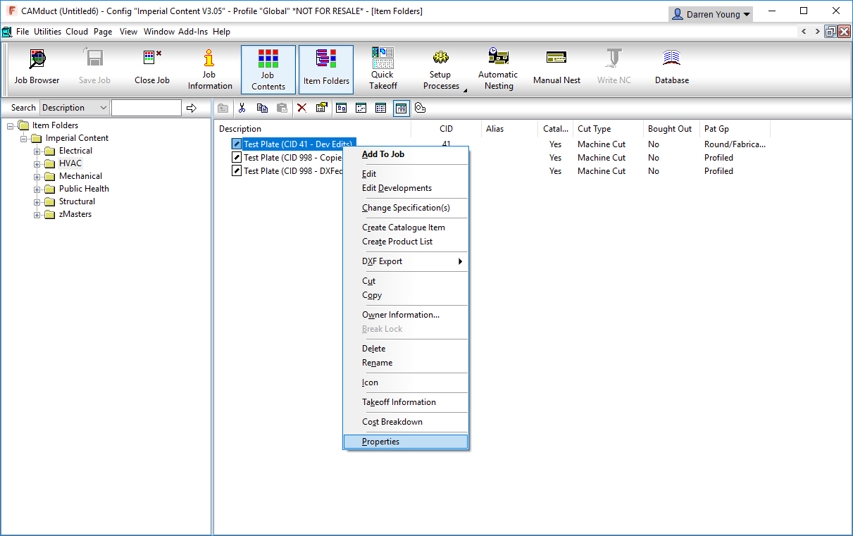
After clicking the Properties option, the properties dialog box will appear. Here, you can switch to the Developments tab to see the developments of the ITM. From this tab, you can then edit the Development Part material. This still presents a few possible difficulties…

  • You have to edit the development part material one ITM at a time.
  • You can’t script changing the development part material
  • You can’t set the development part material to “None” as this is not an option
  • Depending on the “Catalog” and/or other options of the ITM, the Development Part material drop down may not be enabled for selection.

As we mentioned earlier, a native OPUS part CID only contains the developments and avoids a lot of these issues.

The obvious thing to do is to go to the edited developments of the original ITM and copy the geometry to the Windows Clipboard (Ctrl-C). You could then go to an Empty OPUS part and paste the object there from the Windows Clipboard (Ctrl-V). But again, this presents yet more issues.

Even though you would only be copying/pasting the development entities, CAMduct still remembers there were seams and connectors applied and this data hitch hikes along for the ride on the geometry even though you can’t see it. Except now, you can’t get to the ITM editor any longer to change them and COD scripts can’t find any connectors to seams to change because an Opus part doesn’t have those options. The information i there,, hidden, but inaccessible.

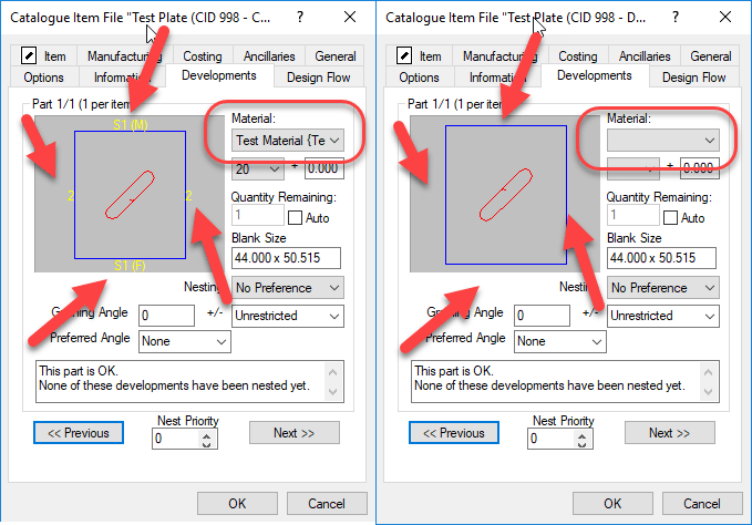
In the following image, you’ll see two ITM Properties dialog boxes side by side.

In the LEFT image, you’ll see what the Developments tab looks like on an ITM with edited Developments or even. It alo look this way on an OPUS part that was created using Copy/Paste method from a different CID. The OPUS Editor doesn’t show you, but the Developments tab in Properties displays text for the Seams/Connectors.  The image in the RIGHT is an OPUS part created with a completely different process that we’ll show shortly.

Also notice the image on the LEFT shows a material in the drop down list where as the image on the RIGHT does not. Using the ITM that was the source of the Left image will bring in proxy Materials, Seams and Connectors if they no longer exist in your configuration. Using the ITM that was the source for the Right image, will not bring in these Proxy items. This means if you later reorganize your materials/seams/connectors, the ITM for the left image will keep corrupting your database and the ITM for the right image will not.

The Solution

To resolve both of these issues, Edited Developments on none OPUS CID Patterns and eliminating proxy database entries, we can use the same process. This process involve creating DXF files for the existing ITM’s an then creating new ITM’s from those same DXF files.

The following image shows how to Right-Click on the ITM and Export the DXF to a file on disk.
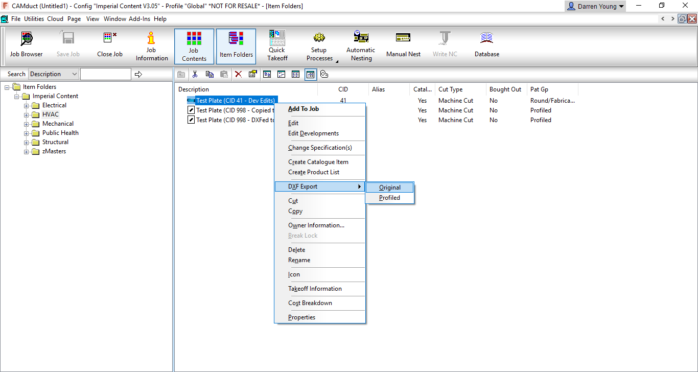
Once the DXF files are create, you can Right-Click on an empty area of the Folder display and select New, then Import as shown in the following image.
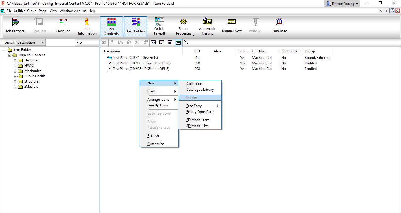
The import process is fairly self explanatory end leaves you in the Opus part editor. Here are can make any final changes and when clicking OK, you can overwrite the existing ITM or give it a new name. This new ITM is based on CID 998, has no material set in the developments and contains no traces of any seams or connectors. You also don’t need to worry about accidentally deleting the edited developments because editing this ITM brings you directly to the OPUS Part editor and does not bring you to the ITM editor.


Additional Considerations

What’s nice about the above process, is that you can select multiple ITM’s at one time to Export to DXF. And when you Import the DXF’s, you can also select multiple DXF files. There will be some additional or changed prompts in this process but it allows you to quickly clean up your existing OPUS parts and protect ITM’s made from non-OPUS CID’s.

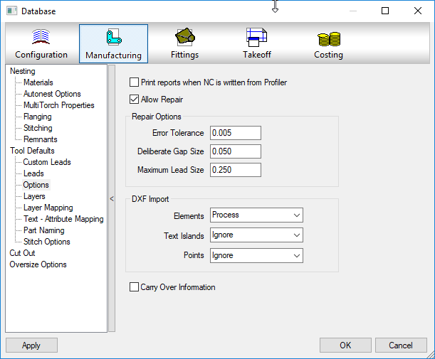
One thing to watch for is complex geometry with a lot of curves/arcs/lines. You’d typically see this type of geometry when cutting patterns that represent art or a lot of text. When dealing with this type of geometry, before you Import the DXF’s, you may want to explore some of the settings used by CAMduct to automatically detect a complete profile without any small gaps or overlaps causing issues, The following image shows where these settings can be made.

Use of these settings goes beyond the scope of this article so I’d recommend using a little trial and error to get the best results only if you encounter problems with importing DXF’s.
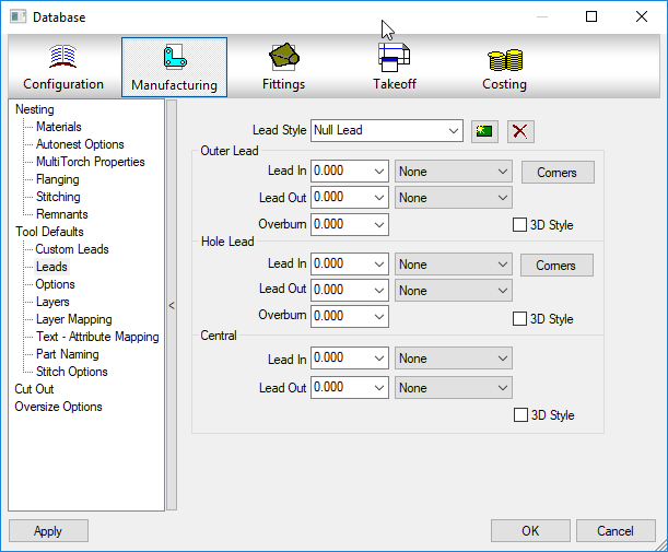
The other thing to watch for is the Kerf or offset used on the tools assigned to the profiled part and which types of lead in/out paths are used to start and end the profiles, While you can always edit these settings of the OPUS parts later on a case by case basis, you can set the defaults to use in CAMduct. The following image shows where to set these default values.

Taking a Closer Look

If you want to take a closer look, at the entire process, you can view the process this these two videos.

Here’s the process to cleanup a single ITM…


Here’s the process to cleanup a multiple ITMs…


If you want to play with a couple ITM’s yourself, you can download them here.

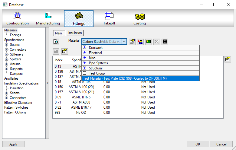
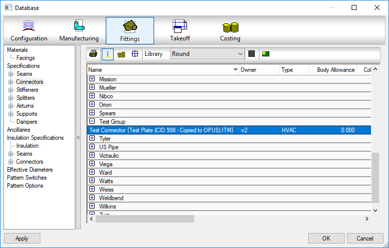
If you play with the original ITM Test Plate (CID 41 – Dev Edits).ITM or the OPUS part created with the flawed Copy//Paste method Test Plate (CID 998 – Copied to OPUS).ITM, you’ll see a custom Material, Seam and Connector added to your database, Delete them out and try again with the next ITM. You’ll see that the ITM created with the DXF process Test Plate (CID 998 – DXFed to OPUS).ITM we showed earlier does not bring the old materials, seams or connectors shown in the below images.
Autodesk Fabrication: Best Practice #3

Don’t leave proxy items in your fabrication database.

You’ll notice these as they appear with curly brackets { } around a piece of text like an ITM name or DWG name.

These proxy objects can show up many places. Services, Service Templates, Materials, Connectors, Seams, etc. They occur when an ITM or drawing containing ITM’s references a database entry that no longer exists in your Fabrication configuration. As an example, if you delete a connector from your database, let’s say “Copper Cup” then later add an ITM to your drawing that contains a reference to that connector, it gets added back to your configuration and displays the ITM name in the curly brackets.

If there’s bracketed items in your database they should either be made permanent or deleted. If deleted, they may keep coming back.  If you truly want them gone, you need to find the objects bringing them back and update them to the new item in your database configuration that they should point to.

A properly managed Fabrication database configuration should have everything configured properly. Items with curly brackets are an indication that things are not configured properly.

Future posts will explain various techniques to help identify where these bracketed items come from as well as how to correct them efficiently.