Fabrication Parts – Riser Clamps in Revit (Problems & Solutions)
I run into a number of people who have had problems with Riser Clamps and Revit Fabrication Parts. I have as well. Here’s how you can work around them…fairly easily.
Problem #1 – Clamp Will Not Attach to Vertical Riser
The first problem I see is with Riser Clamps not attaching to vertical pipe. I’ve seen some creative workarounds. From just placing a clamp in space and moving it to near where it should be to using a modified form of a Grooved Coupling pattern. The following video shows what that would look like if you have this issue.
The fix for this issue is fairly simple. First, make sure you’re using Pattern Number (CID) 838. This is the original Hanger pattern that will allow you to make just about any hanger. Secondly, ensure that you select the ‘Slide‘ option on the pattern.
This is the ONLY Hanger option that will work for vertically oriented pipe.
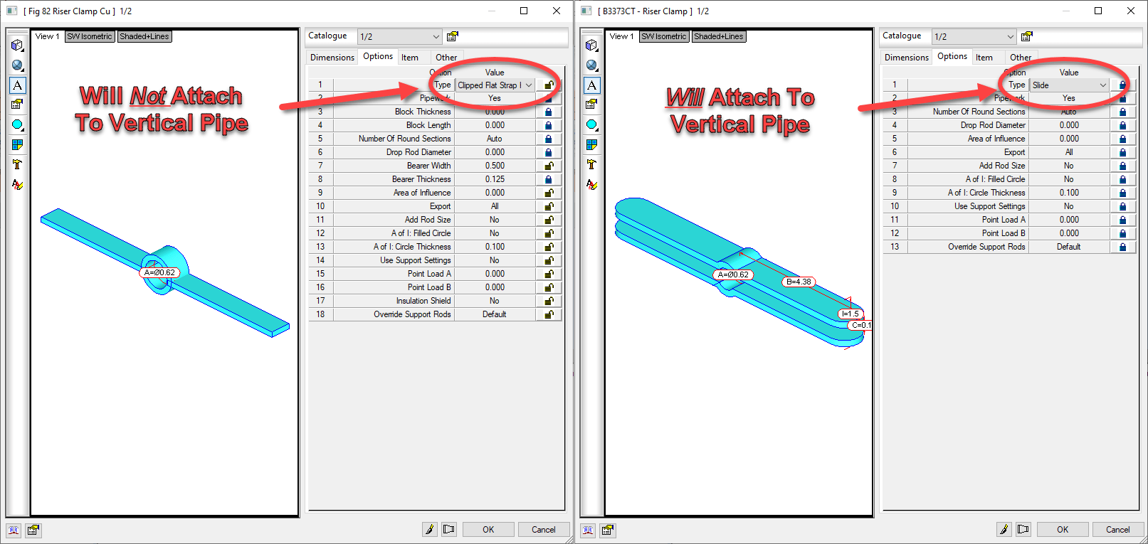
Once you use the proper option, you can observe that a Riser Clamp will attach to the vertical pipe. This can be seen in the following video.
The second Riser Clamp’s configuration uses the ‘Slide’ option. This allows us to attach it to vertical pipe. This sets us up well for the next issue….oversizing.
Issue #2 – Oversized Riser Clamps
The second issue is that if you set your Insulation Specification’s material to Oversize Hangers, the Riser Clamp will also oversize. This isn’t something you do with a Riser Clamp. Many of us have brought this issue to Autodesk on several occasions, yet they seem to struggle with understanding of our need for an option in this pattern to “ignore” oversize.
Luckily, with a little added work and user intervention, we can work around this. To resolve the issue, create a secondary Riser Insulation Specification with a material that does not oversize hangers.
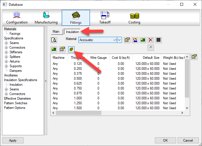
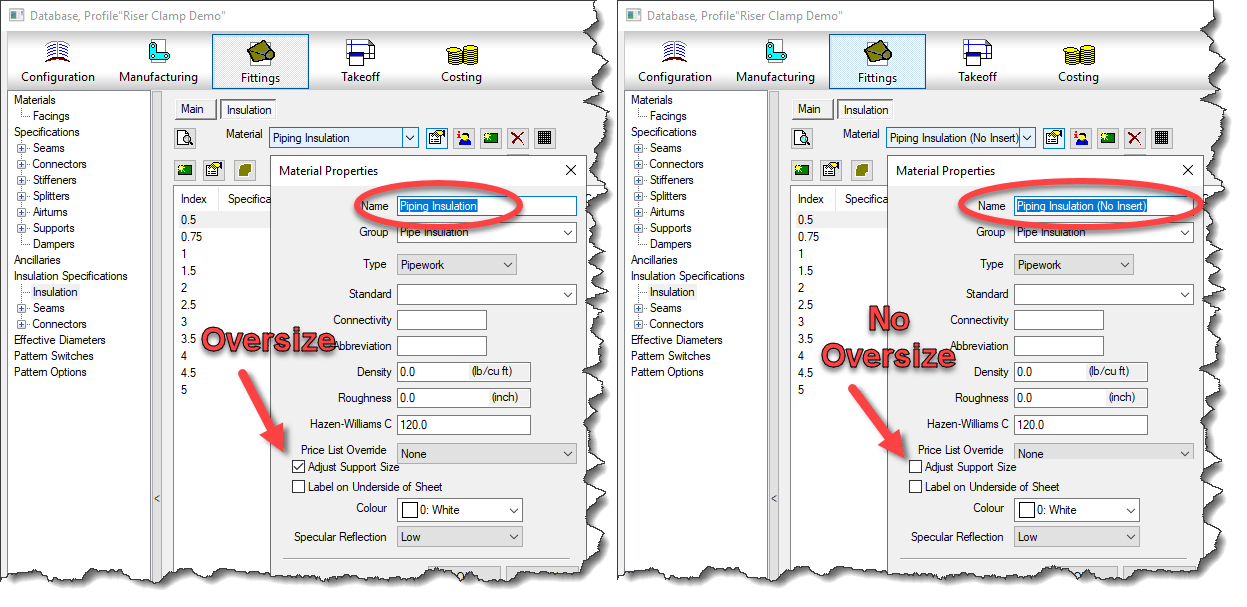
To do this, you’ll need a duplicate of your Insulation Material. In the image below, we configure the insulation on the right not to oversize for systems where we do not require thermal pipe inserts.
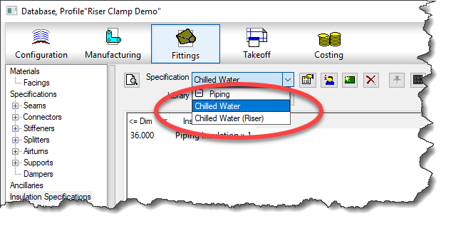
Once you have a secondary Insulation material, you can create the Insulation Specification for the Riser.
Now, all you need to do is override the Insulation Specification on the Riser (vertical pipe) before placing the Riser Clamp. You can see this in the following video.
You can see how the vertical pipe get’s a pipe sized Clamp, where as the horizontal pipe will still oversize because we didn’t change it’s insulation specification.
I’d like to thank Kevin Allen and William Tucker of Comfort Systems USA for pointing out this embarrassingly simple workaround for Insulation Specification that seemed to escaped me.