Autodesk Fabrication: Best Practice #10
Don’t use Ancillaries with Breakpoints inside an Ancillary Kit.
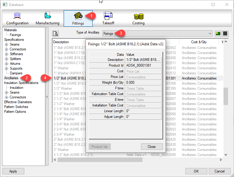
Ancillaries are virtual items you can add to your Fabrication configuration. ESTmep users use Ancillaries to help quantify cost and labor. Material quantification for purchasing and/or fabrication is another use for Ancillaries. These are virtual items because they typically don’t affect modeling or coordination. They aren’t even typically drawn yet they are critical to your fabrication as a purchased, fabricated or installed item.
At times, you many need multiple Ancillaries associated with an item. However the fabrication software typically only allows you to assign a single ancillary to an item or database entry like a connector. For this reason, Autodesk Fabrication includes a type of entry called an “Ancillary Kit” in which you place multiple Ancillaries.
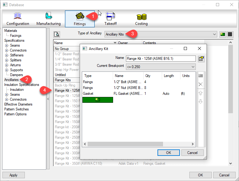
These Ancillary Kits are where you can group multiple Ancillaries that are often used together. A Bolt, Nut and Washers are a good example of an Ancillary Kit.

Ancillary / Kit Breakpoints
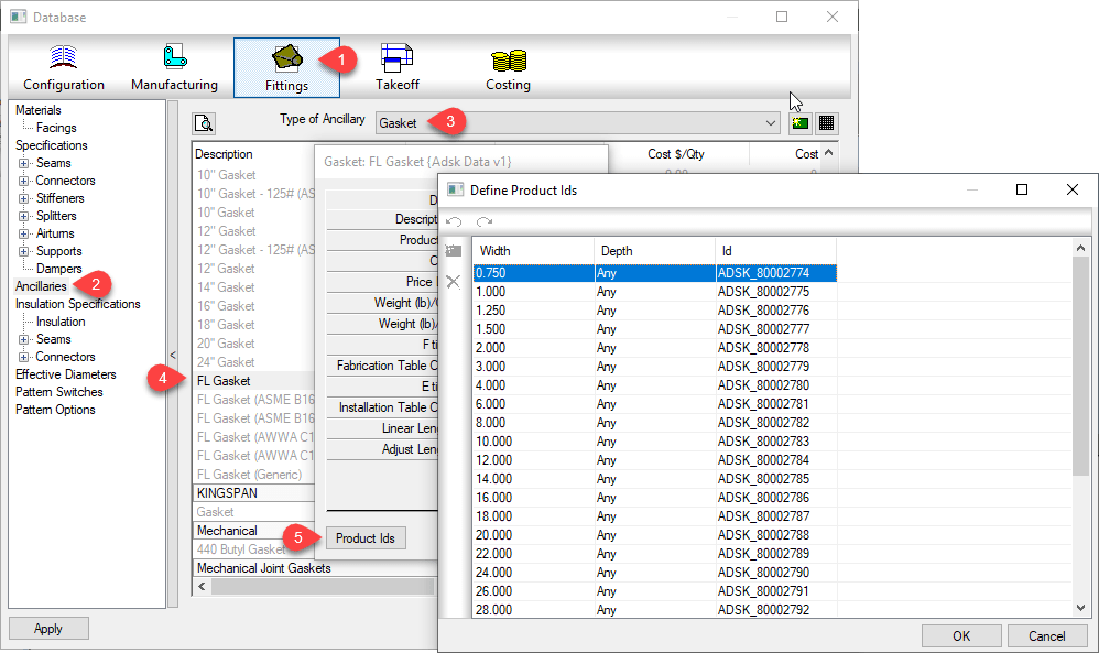
Often, Ancillary items are defined by the size of the item they are associated with. As an example, a flange gasket would be different depending on the type and size of flange it’s used with. You can configure an Ancillary to have Breakpoints to reference a different parts depending on the size of the item the Ancillary is associated with.
Just like Ancillariess, an Ancillary Kit can also have Breakpoints. Using a flange as our example again, depending on the type and size of a flange, or what it’s connecting to (another flange, valve, pump) it can have different bolt/nut sizes and quantities. You would manage this using an Ancillary Kit with Breakpoints.
Nested Breakpoints
If you watched the example images closely, you can see Autodesk’s own database breaks this Best Practice rule. The rule is to never add Ancillaries that use Breakpoints to an Ancillary Kit. Here’s how to keep that straight…
- Yes – Ancillary in Ancillary Kit
- No – Ancillary w/Breakpoints in Ancillary Kit
- Yes – Ancillary in Ancillary Kit with breakpoints
- No – Ancillary w/Breakpoints in Ancillary Kit w/Breakpoints
I’ve not tested Autodesk’s configuration for reporting accuracy. I have enough work managing my own fabrication configuration. However I did create a sample of my own and submitted to Autodesk support. After demonstrating inconsistent results with my sample, their recommended guidance was not to use Ancillaries with Breakpoints in an Ancillary Kit.
Based on testing in other data sets, I would say this is sound advice. Even if you can get it to work, the setup and configuration is less intuitive and confusing. Your Ancillary Kit can reference different Ancillary types using different Breakpoint criteria. The Ancillary Kit could also have conflicting Breakpoint criteria (e.g. Length x Width vs Diameter) compared to the Ancillary.
Keeping this Best Practice can create more Ancillary entries as well as make building Ancillary Kits a little more time consuming. But the results will be more predictable and what’s really happening in your configuration will be more obvious and less obscure. Even where Breakpointed Ancillaries do function within an Ancillary Kit, it’s advised to avoid this where possible.